EP2722472A2 - Ferrure pour battant et séparation de douche - Google Patents
Ferrure pour battant et séparation de douche Download PDFInfo
- Publication number
- EP2722472A2 EP2722472A2 EP13004868.9A EP13004868A EP2722472A2 EP 2722472 A2 EP2722472 A2 EP 2722472A2 EP 13004868 A EP13004868 A EP 13004868A EP 2722472 A2 EP2722472 A2 EP 2722472A2
- Authority
- EP
- European Patent Office
- Prior art keywords
- fitting
- door leaf
- support
- die
- support element
- Prior art date
- Legal status (The legal status is an assumption and is not a legal conclusion. Google has not performed a legal analysis and makes no representation as to the accuracy of the status listed.)
- Granted
Links
Images



Classifications
-
- E—FIXED CONSTRUCTIONS
- E05—LOCKS; KEYS; WINDOW OR DOOR FITTINGS; SAFES
- E05F—DEVICES FOR MOVING WINGS INTO OPEN OR CLOSED POSITION; CHECKS FOR WINGS; WING FITTINGS NOT OTHERWISE PROVIDED FOR, CONCERNED WITH THE FUNCTIONING OF THE WING
- E05F1/00—Closers or openers for wings, not otherwise provided for in this subclass
- E05F1/08—Closers or openers for wings, not otherwise provided for in this subclass spring-actuated, e.g. for horizontally sliding wings
- E05F1/10—Closers or openers for wings, not otherwise provided for in this subclass spring-actuated, e.g. for horizontally sliding wings for swinging wings, e.g. counterbalance
- E05F1/1041—Closers or openers for wings, not otherwise provided for in this subclass spring-actuated, e.g. for horizontally sliding wings for swinging wings, e.g. counterbalance with a coil spring perpendicular to the pivot axis
- E05F1/105—Closers or openers for wings, not otherwise provided for in this subclass spring-actuated, e.g. for horizontally sliding wings for swinging wings, e.g. counterbalance with a coil spring perpendicular to the pivot axis with a compression spring
-
- A—HUMAN NECESSITIES
- A47—FURNITURE; DOMESTIC ARTICLES OR APPLIANCES; COFFEE MILLS; SPICE MILLS; SUCTION CLEANERS IN GENERAL
- A47K—SANITARY EQUIPMENT; ACCESSORIES THEREFOR, e.g. TOILET ACCESSORIES
- A47K3/00—Baths; Showers; Appurtenances therefor
- A47K3/28—Showers or bathing douches
- A47K3/30—Screens or collapsible cabinets for showers or baths
- A47K3/36—Articulated screens
-
- E—FIXED CONSTRUCTIONS
- E05—LOCKS; KEYS; WINDOW OR DOOR FITTINGS; SAFES
- E05D—HINGES OR SUSPENSION DEVICES FOR DOORS, WINDOWS OR WINGS
- E05D15/00—Suspension arrangements for wings
- E05D15/48—Suspension arrangements for wings allowing alternative movements
- E05D15/54—Suspension arrangements for wings allowing alternative movements for opening both inwards and outwards
-
- E—FIXED CONSTRUCTIONS
- E05—LOCKS; KEYS; WINDOW OR DOOR FITTINGS; SAFES
- E05D—HINGES OR SUSPENSION DEVICES FOR DOORS, WINDOWS OR WINGS
- E05D5/00—Construction of single parts, e.g. the parts for attachment
- E05D5/02—Parts for attachment, e.g. flaps
- E05D5/0246—Parts for attachment, e.g. flaps for attachment to glass panels
-
- A—HUMAN NECESSITIES
- A47—FURNITURE; DOMESTIC ARTICLES OR APPLIANCES; COFFEE MILLS; SPICE MILLS; SUCTION CLEANERS IN GENERAL
- A47K—SANITARY EQUIPMENT; ACCESSORIES THEREFOR, e.g. TOILET ACCESSORIES
- A47K3/00—Baths; Showers; Appurtenances therefor
- A47K3/28—Showers or bathing douches
- A47K3/30—Screens or collapsible cabinets for showers or baths
- A47K3/36—Articulated screens
- A47K2003/367—Hinges urging the articulated screen in one or more stable positions
-
- E—FIXED CONSTRUCTIONS
- E05—LOCKS; KEYS; WINDOW OR DOOR FITTINGS; SAFES
- E05Y—INDEXING SCHEME ASSOCIATED WITH SUBCLASSES E05D AND E05F, RELATING TO CONSTRUCTION ELEMENTS, ELECTRIC CONTROL, POWER SUPPLY, POWER SIGNAL OR TRANSMISSION, USER INTERFACES, MOUNTING OR COUPLING, DETAILS, ACCESSORIES, AUXILIARY OPERATIONS NOT OTHERWISE PROVIDED FOR, APPLICATION THEREOF
- E05Y2201/00—Constructional elements; Accessories therefor
- E05Y2201/60—Suspension or transmission members; Accessories therefor
- E05Y2201/622—Suspension or transmission members elements
- E05Y2201/638—Cams; Ramps
-
- E—FIXED CONSTRUCTIONS
- E05—LOCKS; KEYS; WINDOW OR DOOR FITTINGS; SAFES
- E05Y—INDEXING SCHEME ASSOCIATED WITH SUBCLASSES E05D AND E05F, RELATING TO CONSTRUCTION ELEMENTS, ELECTRIC CONTROL, POWER SUPPLY, POWER SIGNAL OR TRANSMISSION, USER INTERFACES, MOUNTING OR COUPLING, DETAILS, ACCESSORIES, AUXILIARY OPERATIONS NOT OTHERWISE PROVIDED FOR, APPLICATION THEREOF
- E05Y2900/00—Application of doors, windows, wings or fittings thereof
- E05Y2900/10—Application of doors, windows, wings or fittings thereof for buildings or parts thereof
- E05Y2900/114—Application of doors, windows, wings or fittings thereof for buildings or parts thereof for showers
Definitions
- the present invention relates to a rotary wing fitting, in particular for swing doors. Furthermore, the invention relates to a shower enclosure, comprising the rotary wing fitting.
- Turntable fittings are used to pivotally connect a door leaf to a frame or adjacent wall.
- the door can be pivoted from its closed position in both directions.
- the prior art knows different methods for locking the door leaf in certain angular positions, for example in the open or in the closed position.
- a lateral surface is defined.
- this lateral surface is defined on the Hubkurvenelement.
- the lateral surface is in particular parallel to the axis of rotation.
- a circumferential direction is defined around the axis of rotation.
- the lateral surface is subdivided into the already mentioned planar surface and into at least one further surface.
- the tappet rests either against the flat surface or at one of the further surfaces.
- the other surfaces can also be flat or round.
- the use of multiple planar surfaces allows the door leaf to be locked at various angular positions.
- a round surface allows a very easy movement of the door leaf, since the spring-loaded plunger can be pressed relatively well through the round surface.
- the round surface can also be called a convex surface.
- the plunger is at least partially disposed in the support element.
- the plunger is completely in the support element.
- a head surface is defined.
- This head surface is applied to the axle device. It is preferably provided that this head surface is flat.
- the planar head surface particularly preferably has an area of at least 0.25 cm 2 . With these at least 0.25 cm 2 , the top surface is completely on the flat surface of the axle device. Accordingly, the planar surface of the axle device is at least as large as the top surface of the plunger. Due to the sufficiently large areas a correspondingly low surface pressure and low wear is possible.
- the head surface of the plunger is formed spherical or arcuate.
- the top surface of the plunger is thus convex.
- the spherical or curved shape of the head surface has a radius of at least 5 mm. Due to the correspondingly large spherical or curved shape it is ensured that the plunger does not deform the plane surface on the axle device.
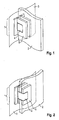
- Fig. 1 shows the rotary wing fitting 1, comprising a first fitting device 4 and a second fitting device 5.
- the first fitting device 4 is mounted on a glass wall 3.
- the second fitting device 5 is mounted on a door leaf 2.
- the door leaf 2 is made of a glass plate.
- Fig. 1 shows the door in closed position.
- Fig. 2 shows the door in an open position. The arrangement is designed as a swing door, so that the door from the in Fig. 1 shown position in both directions can be pivoted by 90 °.
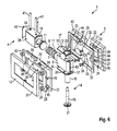
- Fig. 3 shows an exploded view of the Dreherielbetsches1.
- the first fitting device 4 comprises a support element 6, which via a mounting plate 9 is firmly connected to the wall 3.
- the support member 6 extends from the mounting plate 9 perpendicular to a rotational axis 34 of the rotary wing fitting. 1
- a plunger 7 is guided linearly movable perpendicular to the axis of rotation 34.
- the plunger 7 is spring-loaded by a spring 8 in the direction of the axis of rotation 34.
- the spring 8 is supported with one side against the plunger 7 and with the other side against the mounting plate 9.
- spring stops 11 between the spring 8 and the plunger 7 and between the spring 8 and the mounting plate 9 are provided.
- the mounting plate 9 has a through hole 10. About this through hole 10, a spring adjusting screw 56 is inserted, by means of which the spring stop 11, which is located between the spring 8 and the plunger 7, is adjustable. By means of the spring adjusting screw 56 thus acting on the plunger 7 spring force is adjustable.
- the mounting plate 9 is screwed to the wall 3, for example.
- First covers 12 form a visually appealing conclusion of the mounting plate 9 and cover any fasteners.
- axle hole 13 is formed concentrically to the axis of rotation 34.
- An axle device 14 is inserted in this axle hole 13.
- the axle device 14 is formed by a bolt 15 and a lifting cam element 16, which is mounted on the bolt 15 in a rotationally fixed manner.
- the Hubkurvenelement 16 is formed as a cuff. Inside the support member 6, the plunger 7 presses against the Hubkurvenelement 16 of the axle 14th
- a sealing plate 17 is arranged in each case.
- the sealing plates 17 each have a tab 18. These tabs 18 protrude into recesses 19 which are formed in the mounting plate 19.
- Each of the two sealing plates 17 has a recess 20.
- the recesses 20 are arranged coaxially with the axis of rotation 34.
- the recesses 20 and the axle hole 13 are closed on both sides, each with a lid 21.
- the bolt 15 projects through the two covers 21.
- the bolt 15 can be rotatably arranged in the two covers 21.
- the sealing plates 17 have, measured parallel to the axis of rotation 34, a lower height than the cover 21.
- the second fitting device 5 has a first fitting half 22 and a second fitting half 23.
- the first fitting half 22 is also referred to as a base plate.
- the second fitting half 23 is also referred to as a clamping plate.
- the door 2 is clamped between the two fitting halves 22, 23.
- fittings 24 are provided.
- the screwed connections 24 comprise corresponding screws, holes and internal threads in the two fitting halves 22, 23 in order to clamp the door leaf 2.
- the second fitting device 5, and in particular the two fitting halves 22, 23, are configured U-shaped.
- each of the fitting halves 22, 23 has two opposite legs 25.
- the legs 25 extend in particular perpendicular to the axis of rotation 34. Between the legs 25, the support element 6 is arranged. Accordingly, the door is recessed, so that the support element 6 between the legs 25 takes place.
- the second fitting device 5 is rotatably connected to the bolt 15 of the axle device 14.
- 22 clamping arrangements are provided in both legs 25 of the first fitting half.
- Each of the clamping assemblies comprises a hole 26 in which the bolt 15 is inserted.
- the hole 26 merges into a slot 27.
- a screw 28 is screwed.
- the screw 26 extends coaxially with the axis of rotation 34.
- the screw 28 preferably extends perpendicular to the axis of rotation 34 and is spaced from the axis of rotation 34.
- the screw 28 can be actuated via an access hole 26.
- the access hole 26 is located in the second fitting half 28.
- an intermediate layer 30 is preferably glued to protect the glass.
- At least the second fitting half 23 is covered with a second cover 21 so as to cover the screw 24.
- Fig. 4 shows in detail the formation of the Hubkurveniatas 16. Shown is a plan view and an isometric view of the Hubkurveniatas 16.
- the Hubkurvenelement 16 has a lateral surface 32.
- the plunger 7 is located with a top surface 37 (see Fig. 3 ) on the lateral surface 32.
- the circumferential surface 32 extends in the circumferential direction about the axis of rotation 34.
- the lateral surface 32 has a planar surface 35 and a further surface 36.
- the flat surface 35 is parallel to the axis of rotation 34.
- the further surface 36 is formed as a round surface.
- the plunger 7 In the closed position of the door leaf 2, the plunger 7 abuts the flat surface 35. Upon actuation of the door leaf 2 rotates the flat surface 35 and thus pushes the plunger 7 against the spring 8. Thus, a certain resistance during actuation of the door leaf 2 feel. The door 2 is locked in its closed position. Only by overcoming the spring force of the door 2 can be opened. At a corresponding angular position of the door leaf 2, the plunger 7 abuts against the further surface 36. Since the further surface 36 in the illustrated embodiment is round, the door leaf 2 can be moved in these angular positions with relatively little force.
- Fig. 5 shows in detail the formation of the cam member 16 according to a further embodiment.
- the lateral surface 32 has the flat surface 35 and two further surfaces 36.
- One of the other two Surface 36 is round.
- the other further surface 36 is flat.
- the first fitting device 4 in Fig. 3 serves to attach the support element 6 to a wall 3, which is perpendicular to the closed door 2.
- Fig. 6 shows an exploded view of an embodiment of the rotary wing fitting 1, in which the adjacent wall 3 is parallel to the closed door 2.
- the first fitting device comprises a block 38, which instead of the mounting plate 9 in Fig. 3 is used.
- the block 38 is inserted into a corresponding recess of the wall 3.
- each further sealing plates 39 are provided at the top and bottom of the block 38 .
- the two further sealing plates 39 each have the recess 19 into which the tabs 18 of the sealing plates 17 engage.
- the first fitting device 4 comprises further fitting halves 40.
- the other fitting halves 40 serve to clamp the wall 3.
- the other fitting halves 40 are connected via screw connections 41 and corresponding fastening holes 42 with each other and with the block 38.
- the other fitting halves 40 form a U-shape. This U-shape in turn has opposite legs 25. Between the legs 25 of the block 38 is arranged.
- the block 38 is firmly connected to the support element 6.
- the spring stop 11 on the side facing away from the plunger 7 of the spring 8 may be formed as a spring set screw in the block 38.
- a sealing lip 43 is provided on the side facing away from the plunger 8 of the block 38.
- a similar sealing lip 43 is located on the side facing away from the plunger 7 of the support element 6.
- the sealing lips 43 each seal to the fitting devices 4, 5 from.
- Both fitting devices 4, 5 have at least on one side of the door leaf 2 first covers 12 and second covers 31.
- the covers 12, 31 are connected via small pins 45 with the respective fitting halves 23, 40.
- the covers 12, 31 are clipped onto these small pins 45.
- the small pins 45 are in particular spring loaded.
- FIGS. 7 and 8 Based on FIGS. 7 and 8 the formation of flush surfaces on the rotary wing fitting 1 will be described.
- the FIGS. 7 and 8 show the door 2, which is in a closed position perpendicular to the wall 3.
- selbige training of the flush surfaces is also according to the embodiment Fig. 6 intended.
- the support element 6 has two opposite first support outer surfaces 49. Perpendicular to the two first bearing outer surfaces 49 is a second support outer surface 50. This can be seen only in the open state of the door leaf 2.
- the second fitting device 5 has two opposite first fitting outer surfaces 51. These first fitting outer surfaces 51 are formed by the second cover 31 and the outer side of the first fitting half 22, respectively. Furthermore, the second fitting device 5 has a second fitting outer surface 52. This includes in particular flush with a Stirnsete 55 of the door leaf 2. The end face 55 of the door leaf 2 is in the closed state of the same wall 3 and the first fitting device 5 faces.
- the support element 6 extends perpendicular to the axis of rotation 34 over a support width 46. This is measured on the second support outer surface 50. Between the two opposite first outer fitting surfaces 51 a fitting width 47 is defined. A fitting depth 48 defines the distance of the axis of rotation 34 from the second fitting outer surface 52.
- a clear support depth 52 defines the distance of the second support outer surface 50 from the first cover 12.
- the clear support depth 53 corresponds to the fitting width 47.
- Each gap is defined by two opposite edges 54.
- the edges 54 are as sharp as possible and have the smallest possible radius or the smallest possible chamfer, so that when cleaning the surfaces no dirt is pushed into the column and the gaps are as fluid-tight as possible.
Landscapes
- Health & Medical Sciences (AREA)
- Public Health (AREA)
- Engineering & Computer Science (AREA)
- Mechanical Engineering (AREA)
- Epidemiology (AREA)
- General Health & Medical Sciences (AREA)
- Hinges (AREA)
- Power-Operated Mechanisms For Wings (AREA)
- Extensible Doors And Revolving Doors (AREA)
- Specific Sealing Or Ventilating Devices For Doors And Windows (AREA)
- Wing Frames And Configurations (AREA)
Applications Claiming Priority (2)
| Application Number | Priority Date | Filing Date | Title |
|---|---|---|---|
| DE102012110034 | 2012-10-19 | ||
| DE102013008211.0A DE102013008211B4 (de) | 2012-10-19 | 2013-05-14 | Drehflügelbeschlag und Duschabtrennung |
Publications (3)
| Publication Number | Publication Date |
|---|---|
| EP2722472A2 true EP2722472A2 (fr) | 2014-04-23 |
| EP2722472A3 EP2722472A3 (fr) | 2017-06-28 |
| EP2722472B1 EP2722472B1 (fr) | 2021-07-21 |
Family
ID=49356175
Family Applications (1)
| Application Number | Title | Priority Date | Filing Date |
|---|---|---|---|
| EP13004868.9A Active EP2722472B1 (fr) | 2012-10-19 | 2013-10-10 | Ferrure pour battant et séparation de douche |
Country Status (3)
| Country | Link |
|---|---|
| EP (1) | EP2722472B1 (fr) |
| DE (1) | DE102013008211B4 (fr) |
| ES (1) | ES2895931T3 (fr) |
Cited By (2)
| Publication number | Priority date | Publication date | Assignee | Title |
|---|---|---|---|---|
| DE202020101419U1 (de) | 2020-03-13 | 2021-06-15 | Bohle Ag | Abdeckelement für ein Gelenkband und entsprechendes Gelenkband |
| CN115788238A (zh) * | 2022-12-08 | 2023-03-14 | 福建西河卫浴科技有限公司 | 一种门扇及门 |
Family Cites Families (4)
| Publication number | Priority date | Publication date | Assignee | Title |
|---|---|---|---|---|
| US5499428A (en) * | 1994-01-31 | 1996-03-19 | Okada; Paul M. | Flush hinge for athletic court doors |
| DE19717118A1 (de) * | 1997-04-23 | 1998-10-29 | Winkhaus Fa August | Drehlager |
| DE202008001656U1 (de) * | 2008-02-05 | 2008-04-24 | Huang, Shih-Chang, Daliao Shiang | Verstellbares Glastürscharnier |
| DE102009034740A1 (de) * | 2009-07-24 | 2011-01-27 | Dorma Gmbh + Co. Kg | Drehbar gelagerte Tür mit einem Band |
-
2013
- 2013-05-14 DE DE102013008211.0A patent/DE102013008211B4/de active Active
- 2013-10-10 EP EP13004868.9A patent/EP2722472B1/fr active Active
- 2013-10-10 ES ES13004868T patent/ES2895931T3/es active Active
Non-Patent Citations (1)
| Title |
|---|
| None |
Cited By (3)
| Publication number | Priority date | Publication date | Assignee | Title |
|---|---|---|---|---|
| DE202020101419U1 (de) | 2020-03-13 | 2021-06-15 | Bohle Ag | Abdeckelement für ein Gelenkband und entsprechendes Gelenkband |
| EP3879056A1 (fr) | 2020-03-13 | 2021-09-15 | Bohle AG | Élément de recouvrement pour une charnière et charnière correspondante |
| CN115788238A (zh) * | 2022-12-08 | 2023-03-14 | 福建西河卫浴科技有限公司 | 一种门扇及门 |
Also Published As
| Publication number | Publication date |
|---|---|
| DE102013008211B4 (de) | 2021-05-06 |
| EP2722472A3 (fr) | 2017-06-28 |
| ES2895931T3 (es) | 2022-02-23 |
| DE102013008211A1 (de) | 2014-04-24 |
| EP2722472B1 (fr) | 2021-07-21 |
Similar Documents
| Publication | Publication Date | Title |
|---|---|---|
| EP1709270B1 (fr) | Fixation de pinces pour le montage de dispositifs de ferrures, tels que fermetures, elements de charniere, poignees dans des passages au travers d'une paroi mince | |
| DE29820711U1 (de) | Drehriegelverschluß mit Zugeinrichtung | |
| EP2682545B1 (fr) | Dispositif de fermeture pour une porte coulissante ou une fenêtre coulissante, et porte coulissante ou fenêtre coulissante | |
| EP3568547A1 (fr) | Système de fermeture à barre coulissante pour un boîtier d'armoire de distribution, ainsi qu'ensemble correspondant et procédé correspondant | |
| EP2722472B1 (fr) | Ferrure pour battant et séparation de douche | |
| EP3175068B1 (fr) | Système de ferrure | |
| EP1893834A1 (fr) | Dispositif d'ouverture de porte electrique pour portes en verre | |
| DE102013008210B4 (de) | Drehflügelbeschlag und Duschabtrennung | |
| DE202013104526U1 (de) | Flächenbündiger Drehspannverschluss | |
| DE3334298C3 (de) | Verschluß für Fenster, Türen oder dergleichen | |
| DE2330788C2 (de) | Scharnier | |
| EP2947221B1 (fr) | Fenêtre de toit et procédé de montage d'une fenêtre de toit | |
| DE202013006582U1 (de) | Vorrichtung zum Auslösen einer Gasfeder | |
| DE102015120712A1 (de) | Fenster zum Verschließen einer Gebäudeöffnung | |
| DE102014226794A1 (de) | Beschlag zum Einbau zwischen einem Flügel und einem festen Rahmen eines Fensters, einer Tür oder dergleichen sowie Fenster, Tür oder dergleichen mit einem derartigen Beschlag | |
| EP3633126A1 (fr) | Ferrure de couvercle destinée à la fixation pivotante d'un couvercle à un corps de meuble et meuble doté d'une telle ferrure de couvercle | |
| EP3990738A1 (fr) | Boîtier pour un entraînement ainsi qu'entraînement | |
| DE102012104181B3 (de) | Flachband für profilgezogene Rahmen- und Türbauteile | |
| DE10212009B4 (de) | Dichtung, insbesondere für eine Rauchschutz-Schiebetür | |
| DE102008004191A1 (de) | Abschließbarer Vorreiber | |
| WO2022242802A1 (fr) | Dispositif de verrouillage doté d'un limiteur de rotation | |
| DE202016101953U1 (de) | Einstellbare Kofferraumdeckelfallenanordnung | |
| DE202017001681U1 (de) | Schloss | |
| EP2947242B1 (fr) | Dispositif de porte coulissante | |
| DE102013012189A1 (de) | Vorrichtung zum Auslösen einer Gasfeder |
Legal Events
| Date | Code | Title | Description |
|---|---|---|---|
| PUAI | Public reference made under article 153(3) epc to a published international application that has entered the european phase |
Free format text: ORIGINAL CODE: 0009012 |
|
| AK | Designated contracting states |
Kind code of ref document: A2 Designated state(s): AL AT BE BG CH CY CZ DE DK EE ES FI FR GB GR HR HU IE IS IT LI LT LU LV MC MK MT NL NO PL PT RO RS SE SI SK SM TR |
|
| AX | Request for extension of the european patent |
Extension state: BA ME |
|
| RAP1 | Party data changed (applicant data changed or rights of an application transferred) |
Owner name: DORMA DEUTSCHLAND GMBH |
|
| PUAL | Search report despatched |
Free format text: ORIGINAL CODE: 0009013 |
|
| AK | Designated contracting states |
Kind code of ref document: A3 Designated state(s): AL AT BE BG CH CY CZ DE DK EE ES FI FR GB GR HR HU IE IS IT LI LT LU LV MC MK MT NL NO PL PT RO RS SE SI SK SM TR |
|
| AX | Request for extension of the european patent |
Extension state: BA ME |
|
| RIC1 | Information provided on ipc code assigned before grant |
Ipc: A47K 3/36 20060101ALI20170522BHEP Ipc: E05D 15/54 20060101ALI20170522BHEP Ipc: E05D 3/08 20060101AFI20170522BHEP Ipc: E05D 5/02 20060101ALI20170522BHEP Ipc: E05F 1/10 20060101ALI20170522BHEP |
|
| RAP1 | Party data changed (applicant data changed or rights of an application transferred) |
Owner name: GRAL SYSTEME GMBH |
|
| STAA | Information on the status of an ep patent application or granted ep patent |
Free format text: STATUS: REQUEST FOR EXAMINATION WAS MADE |
|
| 17P | Request for examination filed |
Effective date: 20171227 |
|
| RBV | Designated contracting states (corrected) |
Designated state(s): AL AT BE BG CH CY CZ DE DK EE ES FI FR GB GR HR HU IE IS IT LI LT LU LV MC MK MT NL NO PL PT RO RS SE SI SK SM TR |
|
| STAA | Information on the status of an ep patent application or granted ep patent |
Free format text: STATUS: EXAMINATION IS IN PROGRESS |
|
| 17Q | First examination report despatched |
Effective date: 20180606 |
|
| GRAP | Despatch of communication of intention to grant a patent |
Free format text: ORIGINAL CODE: EPIDOSNIGR1 |
|
| STAA | Information on the status of an ep patent application or granted ep patent |
Free format text: STATUS: GRANT OF PATENT IS INTENDED |
|
| INTG | Intention to grant announced |
Effective date: 20210223 |
|
| GRAS | Grant fee paid |
Free format text: ORIGINAL CODE: EPIDOSNIGR3 |
|
| GRAA | (expected) grant |
Free format text: ORIGINAL CODE: 0009210 |
|
| STAA | Information on the status of an ep patent application or granted ep patent |
Free format text: STATUS: THE PATENT HAS BEEN GRANTED |
|
| AK | Designated contracting states |
Kind code of ref document: B1 Designated state(s): AL AT BE BG CH CY CZ DE DK EE ES FI FR GB GR HR HU IE IS IT LI LT LU LV MC MK MT NL NO PL PT RO RS SE SI SK SM TR |
|
| REG | Reference to a national code |
Ref country code: GB Ref legal event code: FG4D Free format text: NOT ENGLISH |
|
| REG | Reference to a national code |
Ref country code: CH Ref legal event code: EP |
|
| REG | Reference to a national code |
Ref country code: DE Ref legal event code: R096 Ref document number: 502013015830 Country of ref document: DE |
|
| REG | Reference to a national code |
Ref country code: AT Ref legal event code: REF Ref document number: 1412760 Country of ref document: AT Kind code of ref document: T Effective date: 20210815 |
|
| REG | Reference to a national code |
Ref country code: IE Ref legal event code: FG4D Free format text: LANGUAGE OF EP DOCUMENT: GERMAN |
|
| REG | Reference to a national code |
Ref country code: LT Ref legal event code: MG9D |
|
| REG | Reference to a national code |
Ref country code: NL Ref legal event code: FP |
|
| PGFP | Annual fee paid to national office [announced via postgrant information from national office to epo] |
Ref country code: NL Payment date: 20211026 Year of fee payment: 9 |
|
| PG25 | Lapsed in a contracting state [announced via postgrant information from national office to epo] |
Ref country code: LT Free format text: LAPSE BECAUSE OF FAILURE TO SUBMIT A TRANSLATION OF THE DESCRIPTION OR TO PAY THE FEE WITHIN THE PRESCRIBED TIME-LIMIT Effective date: 20210721 Ref country code: BG Free format text: LAPSE BECAUSE OF FAILURE TO SUBMIT A TRANSLATION OF THE DESCRIPTION OR TO PAY THE FEE WITHIN THE PRESCRIBED TIME-LIMIT Effective date: 20211021 Ref country code: PT Free format text: LAPSE BECAUSE OF FAILURE TO SUBMIT A TRANSLATION OF THE DESCRIPTION OR TO PAY THE FEE WITHIN THE PRESCRIBED TIME-LIMIT Effective date: 20211122 Ref country code: RS Free format text: LAPSE BECAUSE OF FAILURE TO SUBMIT A TRANSLATION OF THE DESCRIPTION OR TO PAY THE FEE WITHIN THE PRESCRIBED TIME-LIMIT Effective date: 20210721 Ref country code: NO Free format text: LAPSE BECAUSE OF FAILURE TO SUBMIT A TRANSLATION OF THE DESCRIPTION OR TO PAY THE FEE WITHIN THE PRESCRIBED TIME-LIMIT Effective date: 20211021 Ref country code: FI Free format text: LAPSE BECAUSE OF FAILURE TO SUBMIT A TRANSLATION OF THE DESCRIPTION OR TO PAY THE FEE WITHIN THE PRESCRIBED TIME-LIMIT Effective date: 20210721 Ref country code: HR Free format text: LAPSE BECAUSE OF FAILURE TO SUBMIT A TRANSLATION OF THE DESCRIPTION OR TO PAY THE FEE WITHIN THE PRESCRIBED TIME-LIMIT Effective date: 20210721 Ref country code: SE Free format text: LAPSE BECAUSE OF FAILURE TO SUBMIT A TRANSLATION OF THE DESCRIPTION OR TO PAY THE FEE WITHIN THE PRESCRIBED TIME-LIMIT Effective date: 20210721 |
|
| PGFP | Annual fee paid to national office [announced via postgrant information from national office to epo] |
Ref country code: ES Payment date: 20211101 Year of fee payment: 9 |
|
| REG | Reference to a national code |
Ref country code: ES Ref legal event code: FG2A Ref document number: 2895931 Country of ref document: ES Kind code of ref document: T3 Effective date: 20220223 |
|
| PG25 | Lapsed in a contracting state [announced via postgrant information from national office to epo] |
Ref country code: PL Free format text: LAPSE BECAUSE OF FAILURE TO SUBMIT A TRANSLATION OF THE DESCRIPTION OR TO PAY THE FEE WITHIN THE PRESCRIBED TIME-LIMIT Effective date: 20210721 Ref country code: LV Free format text: LAPSE BECAUSE OF FAILURE TO SUBMIT A TRANSLATION OF THE DESCRIPTION OR TO PAY THE FEE WITHIN THE PRESCRIBED TIME-LIMIT Effective date: 20210721 Ref country code: GR Free format text: LAPSE BECAUSE OF FAILURE TO SUBMIT A TRANSLATION OF THE DESCRIPTION OR TO PAY THE FEE WITHIN THE PRESCRIBED TIME-LIMIT Effective date: 20211022 |
|
| PGFP | Annual fee paid to national office [announced via postgrant information from national office to epo] |
Ref country code: IT Payment date: 20211221 Year of fee payment: 9 Ref country code: CH Payment date: 20211103 Year of fee payment: 9 Ref country code: BE Payment date: 20211027 Year of fee payment: 9 |
|
| REG | Reference to a national code |
Ref country code: DE Ref legal event code: R097 Ref document number: 502013015830 Country of ref document: DE |
|
| PG25 | Lapsed in a contracting state [announced via postgrant information from national office to epo] |
Ref country code: DK Free format text: LAPSE BECAUSE OF FAILURE TO SUBMIT A TRANSLATION OF THE DESCRIPTION OR TO PAY THE FEE WITHIN THE PRESCRIBED TIME-LIMIT Effective date: 20210721 |
|
| PLBE | No opposition filed within time limit |
Free format text: ORIGINAL CODE: 0009261 |
|
| STAA | Information on the status of an ep patent application or granted ep patent |
Free format text: STATUS: NO OPPOSITION FILED WITHIN TIME LIMIT |
|
| PG25 | Lapsed in a contracting state [announced via postgrant information from national office to epo] |
Ref country code: SM Free format text: LAPSE BECAUSE OF FAILURE TO SUBMIT A TRANSLATION OF THE DESCRIPTION OR TO PAY THE FEE WITHIN THE PRESCRIBED TIME-LIMIT Effective date: 20210721 Ref country code: SK Free format text: LAPSE BECAUSE OF FAILURE TO SUBMIT A TRANSLATION OF THE DESCRIPTION OR TO PAY THE FEE WITHIN THE PRESCRIBED TIME-LIMIT Effective date: 20210721 Ref country code: RO Free format text: LAPSE BECAUSE OF FAILURE TO SUBMIT A TRANSLATION OF THE DESCRIPTION OR TO PAY THE FEE WITHIN THE PRESCRIBED TIME-LIMIT Effective date: 20210721 Ref country code: EE Free format text: LAPSE BECAUSE OF FAILURE TO SUBMIT A TRANSLATION OF THE DESCRIPTION OR TO PAY THE FEE WITHIN THE PRESCRIBED TIME-LIMIT Effective date: 20210721 Ref country code: CZ Free format text: LAPSE BECAUSE OF FAILURE TO SUBMIT A TRANSLATION OF THE DESCRIPTION OR TO PAY THE FEE WITHIN THE PRESCRIBED TIME-LIMIT Effective date: 20210721 Ref country code: AL Free format text: LAPSE BECAUSE OF FAILURE TO SUBMIT A TRANSLATION OF THE DESCRIPTION OR TO PAY THE FEE WITHIN THE PRESCRIBED TIME-LIMIT Effective date: 20210721 |
|
| 26N | No opposition filed |
Effective date: 20220422 |
|
| GBPC | Gb: european patent ceased through non-payment of renewal fee |
Effective date: 20211021 |
|
| PG25 | Lapsed in a contracting state [announced via postgrant information from national office to epo] |
Ref country code: MC Free format text: LAPSE BECAUSE OF FAILURE TO SUBMIT A TRANSLATION OF THE DESCRIPTION OR TO PAY THE FEE WITHIN THE PRESCRIBED TIME-LIMIT Effective date: 20210721 |
|
| PG25 | Lapsed in a contracting state [announced via postgrant information from national office to epo] |
Ref country code: LU Free format text: LAPSE BECAUSE OF NON-PAYMENT OF DUE FEES Effective date: 20211010 Ref country code: GB Free format text: LAPSE BECAUSE OF NON-PAYMENT OF DUE FEES Effective date: 20211021 |
|
| PG25 | Lapsed in a contracting state [announced via postgrant information from national office to epo] |
Ref country code: FR Free format text: LAPSE BECAUSE OF NON-PAYMENT OF DUE FEES Effective date: 20211031 |
|
| PG25 | Lapsed in a contracting state [announced via postgrant information from national office to epo] |
Ref country code: IE Free format text: LAPSE BECAUSE OF NON-PAYMENT OF DUE FEES Effective date: 20211010 |
|
| REG | Reference to a national code |
Ref country code: AT Ref legal event code: MM01 Ref document number: 1412760 Country of ref document: AT Kind code of ref document: T Effective date: 20211010 |
|
| PG25 | Lapsed in a contracting state [announced via postgrant information from national office to epo] |
Ref country code: AT Free format text: LAPSE BECAUSE OF NON-PAYMENT OF DUE FEES Effective date: 20211010 |
|
| PG25 | Lapsed in a contracting state [announced via postgrant information from national office to epo] |
Ref country code: HU Free format text: LAPSE BECAUSE OF FAILURE TO SUBMIT A TRANSLATION OF THE DESCRIPTION OR TO PAY THE FEE WITHIN THE PRESCRIBED TIME-LIMIT; INVALID AB INITIO Effective date: 20131010 |
|
| REG | Reference to a national code |
Ref country code: CH Ref legal event code: PL |
|
| REG | Reference to a national code |
Ref country code: NL Ref legal event code: MM Effective date: 20221101 |
|
| REG | Reference to a national code |
Ref country code: BE Ref legal event code: MM Effective date: 20221031 |
|
| PG25 | Lapsed in a contracting state [announced via postgrant information from national office to epo] |
Ref country code: CY Free format text: LAPSE BECAUSE OF FAILURE TO SUBMIT A TRANSLATION OF THE DESCRIPTION OR TO PAY THE FEE WITHIN THE PRESCRIBED TIME-LIMIT Effective date: 20210721 |
|
| PG25 | Lapsed in a contracting state [announced via postgrant information from national office to epo] |
Ref country code: NL Free format text: LAPSE BECAUSE OF NON-PAYMENT OF DUE FEES Effective date: 20221101 Ref country code: LI Free format text: LAPSE BECAUSE OF NON-PAYMENT OF DUE FEES Effective date: 20221031 Ref country code: CH Free format text: LAPSE BECAUSE OF NON-PAYMENT OF DUE FEES Effective date: 20221031 |
|
| REG | Reference to a national code |
Ref country code: DE Ref legal event code: R082 Ref document number: 502013015830 Country of ref document: DE Representative=s name: KAYSER & COBET PATENTANWAELTE PARTNERSCHAFT, DE |
|
| PG25 | Lapsed in a contracting state [announced via postgrant information from national office to epo] |
Ref country code: BE Free format text: LAPSE BECAUSE OF NON-PAYMENT OF DUE FEES Effective date: 20221031 |
|
| PG25 | Lapsed in a contracting state [announced via postgrant information from national office to epo] |
Ref country code: IT Free format text: LAPSE BECAUSE OF NON-PAYMENT OF DUE FEES Effective date: 20221010 |
|
| REG | Reference to a national code |
Ref country code: ES Ref legal event code: FD2A Effective date: 20231129 |
|
| PG25 | Lapsed in a contracting state [announced via postgrant information from national office to epo] |
Ref country code: ES Free format text: LAPSE BECAUSE OF NON-PAYMENT OF DUE FEES Effective date: 20221011 |
|
| PG25 | Lapsed in a contracting state [announced via postgrant information from national office to epo] |
Ref country code: ES Free format text: LAPSE BECAUSE OF NON-PAYMENT OF DUE FEES Effective date: 20221011 |
|
| PGFP | Annual fee paid to national office [announced via postgrant information from national office to epo] |
Ref country code: DE Payment date: 20231006 Year of fee payment: 11 |
|
| PG25 | Lapsed in a contracting state [announced via postgrant information from national office to epo] |
Ref country code: MK Free format text: LAPSE BECAUSE OF FAILURE TO SUBMIT A TRANSLATION OF THE DESCRIPTION OR TO PAY THE FEE WITHIN THE PRESCRIBED TIME-LIMIT Effective date: 20210721 |
|
| PG25 | Lapsed in a contracting state [announced via postgrant information from national office to epo] |
Ref country code: MT Free format text: LAPSE BECAUSE OF FAILURE TO SUBMIT A TRANSLATION OF THE DESCRIPTION OR TO PAY THE FEE WITHIN THE PRESCRIBED TIME-LIMIT Effective date: 20210721 |
|
| REG | Reference to a national code |
Ref country code: DE Ref legal event code: R119 Ref document number: 502013015830 Country of ref document: DE |
|
| PG25 | Lapsed in a contracting state [announced via postgrant information from national office to epo] |
Ref country code: DE Free format text: LAPSE BECAUSE OF NON-PAYMENT OF DUE FEES Effective date: 20250501 |
|
| PG25 | Lapsed in a contracting state [announced via postgrant information from national office to epo] |
Ref country code: TR Free format text: LAPSE BECAUSE OF FAILURE TO SUBMIT A TRANSLATION OF THE DESCRIPTION OR TO PAY THE FEE WITHIN THE PRESCRIBED TIME-LIMIT Effective date: 20210721 |