EP2724980A1 - Dispositif de remplissage - Google Patents
Dispositif de remplissage Download PDFInfo
- Publication number
- EP2724980A1 EP2724980A1 EP13185948.0A EP13185948A EP2724980A1 EP 2724980 A1 EP2724980 A1 EP 2724980A1 EP 13185948 A EP13185948 A EP 13185948A EP 2724980 A1 EP2724980 A1 EP 2724980A1
- Authority
- EP
- European Patent Office
- Prior art keywords
- valve
- valve housing
- filling device
- spring
- poppet
- Prior art date
- Legal status (The legal status is an assumption and is not a legal conclusion. Google has not performed a legal analysis and makes no representation as to the accuracy of the status listed.)
- Withdrawn
Links
Images



Classifications
-
- B—PERFORMING OPERATIONS; TRANSPORTING
- B67—OPENING, CLOSING OR CLEANING BOTTLES, JARS OR SIMILAR CONTAINERS; LIQUID HANDLING
- B67D—DISPENSING, DELIVERING OR TRANSFERRING LIQUIDS, NOT OTHERWISE PROVIDED FOR
- B67D7/00—Apparatus or devices for transferring liquids from bulk storage containers or reservoirs into vehicles or into portable containers, e.g. for retail sale purposes
- B67D7/06—Details or accessories
- B67D7/42—Filling nozzles
-
- B—PERFORMING OPERATIONS; TRANSPORTING
- B67—OPENING, CLOSING OR CLEANING BOTTLES, JARS OR SIMILAR CONTAINERS; LIQUID HANDLING
- B67D—DISPENSING, DELIVERING OR TRANSFERRING LIQUIDS, NOT OTHERWISE PROVIDED FOR
- B67D3/00—Apparatus or devices for controlling flow of liquids under gravity from storage containers for dispensing purposes
- B67D3/04—Liquid-dispensing taps or cocks adapted to seal and open tapping holes of casks, e.g. for beer
- B67D3/043—Liquid-dispensing taps or cocks adapted to seal and open tapping holes of casks, e.g. for beer with a closing element having a linear movement, in a direction perpendicular to the seat
- B67D3/044—Liquid-dispensing taps or cocks adapted to seal and open tapping holes of casks, e.g. for beer with a closing element having a linear movement, in a direction perpendicular to the seat and venting means operated automatically with the tap
-
- B—PERFORMING OPERATIONS; TRANSPORTING
- B67—OPENING, CLOSING OR CLEANING BOTTLES, JARS OR SIMILAR CONTAINERS; LIQUID HANDLING
- B67D—DISPENSING, DELIVERING OR TRANSFERRING LIQUIDS, NOT OTHERWISE PROVIDED FOR
- B67D7/00—Apparatus or devices for transferring liquids from bulk storage containers or reservoirs into vehicles or into portable containers, e.g. for retail sale purposes
- B67D7/005—Spouts
Definitions
- the invention relates to a filling device for filling a container with liquids. It relates in particular to a filling device for containers with not easily accessible filling openings for consumables of vehicles and mobile power equipment.
- Such a filling device is known in particular for fuels and lubricants for fueling vehicles and mobile power equipment, which consists essentially of two telescopically displaceable sleeves, wherein the inner sleeve has at its outer end a valve plate and the other outer sleeve as a movable, spring-loaded valve seat is trained.
- the object of the invention is to provide a filling device, in particular for the filling of liquid containers on motor vehicles, which can be produced with little effort, which has a high reliability, which is easy to handle and thus suitable for unprofessional general everyday use.
- the invention relates to a filling device for filling a container with liquids, which comprises a tubular valve housing with a flow channel and a valve disposed within the valve housing and at a valve housing end poppet valve for regulating the flow channel.
- the device is characterized in that a shaft of the poppet valve is movably mounted in a valve guide sleeve.
- a valve guide sleeve enclosing, biased between a spring stop and a spring retainer pressure spring is arranged so that by the attacking Spring force a valve disc of the poppet valve tightly closes a flow opening of the valve housing.
- a valve lift of the poppet valve is predetermined by the distance of the spring retaining disk to a stop of the valve guide sleeve.
- the shaft of the poppet valve can be acted upon by a lever shaft with a force acting against the spring force.
- the lever shaft is connected outside of the valve housing with an actuating lever, wherein the actuating lever is movably mounted, such that the actuating lever moves away when opening the poppet valve from the valve housing end.
- a valve guide sleeve with its therein movable shaft of the poppet valve and the valve guide sleeve enclosing, between a spring stopper and a spring retaining disk, biased compression spring is arranged so that the valve disc of the poppet valve, the outlet opening of the valve housing seals.
- a lever of a transverse to the shaft of the poppet valve lever shaft is located adjacent to the contact surface of the shaft of the poppet valve and on the other hand outside of the valve housing, the lever shaft connected by means of a rotationally connected thereto, mounted on two sides operating lever.
- the lever shaft may be sealed to the exterior of the valve housing by means of a radial seal.
- a vent tube extends to close to the inside of the valve disc of the poppet valve, in particular preferably the vent tube is disposed within the valve housing and the valve disc of the poppet valve closes an air passage opening of the valve housing in the closed state also tight.
- the Be Schollvoriquessgetoriuse is cylindrical and dimensioned so that an outlet nozzle of the same is fitting to the usual filling.
- the filling device according to the invention can also be moved to difficult-to-reach filling openings without loss of liquid, because the poppet valve opens only upon actuation of the actuating lever through the edge of the filling opening.
- the filling process with the inflow of filling liquid is automatically interrupted by means of the opening of the vent pipe located directly on the valve disk, as soon as the liquid level of the container to be filled reaches the valve disk.
- the filling device according to the invention preferably consists essentially of plastic moldings and is therefore inexpensive to produce. It is due to their low weight, high reliability and ease of handling especially for filling in vehicles and motor equipment permanently installed containers for cooling water and Windscreen and headlight cleaning water.
- the filling device is suitable by means of a suitable adapter and / or a hose connection variable for use with different storage containers.
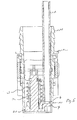
- the filling device comprises a tubular valve housing 6, which forms a flow channel 8 for liquid.
- the filling device is connected to a hose connection 11 and a hose connection end stop 12 via a hose to a washing water reservoir.
- This end of the valve housing 6 thus forms a hose nozzle 17.
- a poppet valve 7 closes a through the valve housing 6 predetermined flow channel 8 at a hose stub 17 opposite valve housing end 16. For this is in the closed state, a valve disc 30 of the poppet valve 7 sealingly at a flow opening 9 for the liquid.
- a pressing force necessary for closing the flow opening 9 is provided by means of a compression spring 3.
- the poppet valve 7 has a shaft 32 which is movably mounted in a valve guide sleeve 24.
- the prestressed compression spring 3 encloses this valve guide sleeve 24 and is seated with one end on a spring stop 19 of the valve housing 6 and finds with its other end their stop on a spring retaining disk 2, which is located in a retaining disk groove 18 of the shaft 32.
- a valve lift results from the distance between stop 13 of the valve guide sleeve 24 and the spring retaining disk. 2
- the lever shaft 5 (here an eccentric shaft), which is mounted in the valve housing 6, is sealed with the radial seal 15 to the outside.
- the liquid flow through the flow passage 8 ends when the liquid level in the wash water tank has reached an air passage opening 10 on the valve housing 6 (see in particular FIGS. 3 to 5 ).
- the filling device is moved with its actuating lever 4 away from the filling opening and thus also the valve 7 is returned by the compression spring 3 in its initial position.
- valve disk 30 of the poppet valve 7 then closes both the liquid flow opening 9 and the air flow opening 10.
- the valve disk 30 has corresponding sealing lips 20, 23.
- the lever shaft 5 is connected to a driver 21 (square) to the operating lever 4 in positive contact (see FIG. 3 ).
Landscapes
- Engineering & Computer Science (AREA)
- Mechanical Engineering (AREA)
- Filling Of Jars Or Cans And Processes For Cleaning And Sealing Jars (AREA)
- Mechanically-Actuated Valves (AREA)
Applications Claiming Priority (1)
| Application Number | Priority Date | Filing Date | Title |
|---|---|---|---|
| DE201210020751 DE102012020751B3 (de) | 2012-10-23 | 2012-10-23 | Befüllvorrichtung |
Publications (1)
| Publication Number | Publication Date |
|---|---|
| EP2724980A1 true EP2724980A1 (fr) | 2014-04-30 |
Family
ID=48084639
Family Applications (1)
| Application Number | Title | Priority Date | Filing Date |
|---|---|---|---|
| EP13185948.0A Withdrawn EP2724980A1 (fr) | 2012-10-23 | 2013-09-25 | Dispositif de remplissage |
Country Status (2)
| Country | Link |
|---|---|
| EP (1) | EP2724980A1 (fr) |
| DE (1) | DE102012020751B3 (fr) |
Cited By (1)
| Publication number | Priority date | Publication date | Assignee | Title |
|---|---|---|---|---|
| CN105197388A (zh) * | 2014-06-20 | 2015-12-30 | 安德烈·斯蒂尔股份两合公司 | 罐填充系统 |
Citations (5)
| Publication number | Priority date | Publication date | Assignee | Title |
|---|---|---|---|---|
| DE883854C (de) * | 1942-03-20 | 1953-07-20 | Pour Tous App S Mecaniques Sa | Zapfpistole fuer Fluessigkeitszapfvorrichtungen, insbesondere Kraftstoffe, mit zwei das Zapfventil belastenden Federn unterschiedlicher Staerke |
| US6435380B1 (en) * | 1999-08-18 | 2002-08-20 | Western Industries, Inc. | Self-sealed spout |
| DE10238752A1 (de) * | 2002-08-23 | 2004-03-04 | Andreas Stihl Ag & Co. | Einrichtung zum Abfüllen von Flüssigkeiten |
| GB2443427A (en) * | 2006-11-03 | 2008-05-07 | Fuel Savers Ltd | Delivery valve |
| DE102009035885A1 (de) * | 2009-08-03 | 2011-02-17 | Fass-Frisch Gmbh | Versenkbarer Zapfhahn |
-
2012
- 2012-10-23 DE DE201210020751 patent/DE102012020751B3/de not_active Expired - Fee Related
-
2013
- 2013-09-25 EP EP13185948.0A patent/EP2724980A1/fr not_active Withdrawn
Patent Citations (6)
| Publication number | Priority date | Publication date | Assignee | Title |
|---|---|---|---|---|
| DE883854C (de) * | 1942-03-20 | 1953-07-20 | Pour Tous App S Mecaniques Sa | Zapfpistole fuer Fluessigkeitszapfvorrichtungen, insbesondere Kraftstoffe, mit zwei das Zapfventil belastenden Federn unterschiedlicher Staerke |
| US6435380B1 (en) * | 1999-08-18 | 2002-08-20 | Western Industries, Inc. | Self-sealed spout |
| DE10238752A1 (de) * | 2002-08-23 | 2004-03-04 | Andreas Stihl Ag & Co. | Einrichtung zum Abfüllen von Flüssigkeiten |
| DE10238752B4 (de) | 2002-08-23 | 2010-09-09 | Andreas Stihl Ag & Co. | Einrichtung zum Abfüllen von Flüssigkeiten |
| GB2443427A (en) * | 2006-11-03 | 2008-05-07 | Fuel Savers Ltd | Delivery valve |
| DE102009035885A1 (de) * | 2009-08-03 | 2011-02-17 | Fass-Frisch Gmbh | Versenkbarer Zapfhahn |
Cited By (2)
| Publication number | Priority date | Publication date | Assignee | Title |
|---|---|---|---|---|
| CN105197388A (zh) * | 2014-06-20 | 2015-12-30 | 安德烈·斯蒂尔股份两合公司 | 罐填充系统 |
| CN105197388B (zh) * | 2014-06-20 | 2018-10-19 | 安德烈·斯蒂尔股份两合公司 | 罐填充系统 |
Also Published As
| Publication number | Publication date |
|---|---|
| DE102012020751B3 (de) | 2013-05-02 |
Similar Documents
| Publication | Publication Date | Title |
|---|---|---|
| DE102008057666B4 (de) | Leckfreie Kartusche mit ovaler Dichtung | |
| EP2293880B1 (fr) | Tête de décharge de fluide | |
| EP1299227B1 (fr) | Dispositif d'etancheification | |
| DE102008049150A1 (de) | Einsatzelement für einen zur tankstellenseitigen Befüllung mit Harnstoff geeigneten Behälter | |
| DE2362422A1 (de) | Selbsttaetig absperrende zapfpistole | |
| EP2988978A2 (fr) | Contenant de fluide sous pression pourvu d'un dispositif d'arrêt | |
| DE202017100771U1 (de) | Trinkflaschenverschluss | |
| DE60111561T2 (de) | Entlüftungsventilanordnung | |
| EP3204669A1 (fr) | Ajutage d'évacuation | |
| DE102014001131A1 (de) | Zapfpistole zur Betankung von Fahrzeugtanks mit wässriger Harnstofflösung (AdBlue) oder ähnlichen Flüssigkeiten | |
| EP2724980A1 (fr) | Dispositif de remplissage | |
| DE202015006027U1 (de) | Frostsichere Auslaufarmatur | |
| AT408970B (de) | Vorrichtung zum verhindern des überfüllens eines kraftstofftankes | |
| EP3815792A1 (fr) | Pompe à mousse | |
| DE2928529C2 (de) | Selbstschlußventil für Gas- und Wasserleitungen | |
| DE102005043745A1 (de) | Entlüftungssystem mit Siphonentleerung | |
| DE202012010094U1 (de) | Befüllvorrichtung | |
| DE2309498A1 (de) | Entlueftungsventil | |
| DE102005041437A1 (de) | Betankungswächter | |
| DE102014101652A1 (de) | Zapfkopf für ein Getränkefass | |
| EP2141087A2 (fr) | Récipient de sortie pouvant être rempli de nouveau pour liquides | |
| DE2754574C2 (fr) | ||
| DE102010035653B3 (de) | Gasgerät, Gasführungseinrichtung und Dichtvorrichtung sowie Verfahren zur Vermeidung von Gasrückströmungen | |
| DE102006015428A1 (de) | Be- und Entlüftungseinrichtung | |
| DE202009008557U1 (de) | Vorrichtung zur Überwachung eines Betankungsvorganges mit verbesserter Restentleerung |
Legal Events
| Date | Code | Title | Description |
|---|---|---|---|
| PUAI | Public reference made under article 153(3) epc to a published international application that has entered the european phase |
Free format text: ORIGINAL CODE: 0009012 |
|
| 17P | Request for examination filed |
Effective date: 20130925 |
|
| AK | Designated contracting states |
Kind code of ref document: A1 Designated state(s): AL AT BE BG CH CY CZ DE DK EE ES FI FR GB GR HR HU IE IS IT LI LT LU LV MC MK MT NL NO PL PT RO RS SE SI SK SM TR |
|
| AX | Request for extension of the european patent |
Extension state: BA ME |
|
| STAA | Information on the status of an ep patent application or granted ep patent |
Free format text: STATUS: THE APPLICATION IS DEEMED TO BE WITHDRAWN |
|
| 18D | Application deemed to be withdrawn |
Effective date: 20141031 |