EP2725317A1 - Wärmetauscherrohr und Wärmetauscher umfassend das entsprechende Rohr - Google Patents
Wärmetauscherrohr und Wärmetauscher umfassend das entsprechende Rohr Download PDFInfo
- Publication number
- EP2725317A1 EP2725317A1 EP14152354.8A EP14152354A EP2725317A1 EP 2725317 A1 EP2725317 A1 EP 2725317A1 EP 14152354 A EP14152354 A EP 14152354A EP 2725317 A1 EP2725317 A1 EP 2725317A1
- Authority
- EP
- European Patent Office
- Prior art keywords
- tube
- legs
- base portion
- folds
- fold
- Prior art date
- Legal status (The legal status is an assumption and is not a legal conclusion. Google has not performed a legal analysis and makes no representation as to the accuracy of the status listed.)
- Granted
Links
Images


Classifications
-
- B—PERFORMING OPERATIONS; TRANSPORTING
- B21—MECHANICAL METAL-WORKING WITHOUT ESSENTIALLY REMOVING MATERIAL; PUNCHING METAL
- B21D—WORKING OR PROCESSING OF SHEET METAL OR METAL TUBES, RODS OR PROFILES WITHOUT ESSENTIALLY REMOVING MATERIAL; PUNCHING METAL
- B21D53/00—Making other particular articles
- B21D53/02—Making other particular articles heat exchangers or parts thereof, e.g. radiators, condensers fins, headers
- B21D53/06—Making other particular articles heat exchangers or parts thereof, e.g. radiators, condensers fins, headers of metal tubes
-
- B—PERFORMING OPERATIONS; TRANSPORTING
- B21—MECHANICAL METAL-WORKING WITHOUT ESSENTIALLY REMOVING MATERIAL; PUNCHING METAL
- B21C—MANUFACTURE OF METAL SHEETS, WIRE, RODS, TUBES, PROFILES OR LIKE SEMI-MANUFACTURED PRODUCTS OTHERWISE THAN BY ROLLING; AUXILIARY OPERATIONS USED IN CONNECTION WITH METAL-WORKING WITHOUT ESSENTIALLY REMOVING MATERIAL
- B21C37/00—Manufacture of metal sheets, rods, wire, tubes, profiles or like semi-manufactured products, not otherwise provided for; Manufacture of tubes of special shape
- B21C37/06—Manufacture of metal sheets, rods, wire, tubes, profiles or like semi-manufactured products, not otherwise provided for; Manufacture of tubes of special shape of tubes or metal hoses; Combined procedures for making tubes, e.g. for making multi-wall tubes
- B21C37/15—Making tubes of special shape; Making tube fittings
- B21C37/22—Making finned or ribbed tubes by fixing strip or like material to tubes
- B21C37/225—Making finned or ribbed tubes by fixing strip or like material to tubes longitudinally-ribbed tubes
-
- B—PERFORMING OPERATIONS; TRANSPORTING
- B23—MACHINE TOOLS; METAL-WORKING NOT OTHERWISE PROVIDED FOR
- B23P—METAL-WORKING NOT OTHERWISE PROVIDED FOR; COMBINED OPERATIONS; UNIVERSAL MACHINE TOOLS
- B23P15/00—Making specific metal objects by operations not covered by a single other subclass or a group in this subclass
- B23P15/26—Making specific metal objects by operations not covered by a single other subclass or a group in this subclass heat exchangers or the like
-
- F—MECHANICAL ENGINEERING; LIGHTING; HEATING; WEAPONS; BLASTING
- F28—HEAT EXCHANGE IN GENERAL
- F28D—HEAT-EXCHANGE APPARATUS, NOT PROVIDED FOR IN ANOTHER SUBCLASS, IN WHICH THE HEAT-EXCHANGE MEDIA DO NOT COME INTO DIRECT CONTACT
- F28D1/00—Heat-exchange apparatus having stationary conduit assemblies for one heat-exchange medium only, the media being in contact with different sides of the conduit wall, in which the other heat-exchange medium is a large body of fluid, e.g. domestic or motor car radiators
- F28D1/02—Heat-exchange apparatus having stationary conduit assemblies for one heat-exchange medium only, the media being in contact with different sides of the conduit wall, in which the other heat-exchange medium is a large body of fluid, e.g. domestic or motor car radiators with heat-exchange conduits immersed in the body of fluid
- F28D1/03—Heat-exchange apparatus having stationary conduit assemblies for one heat-exchange medium only, the media being in contact with different sides of the conduit wall, in which the other heat-exchange medium is a large body of fluid, e.g. domestic or motor car radiators with heat-exchange conduits immersed in the body of fluid with plate-like or laminated conduits
- F28D1/0391—Heat-exchange apparatus having stationary conduit assemblies for one heat-exchange medium only, the media being in contact with different sides of the conduit wall, in which the other heat-exchange medium is a large body of fluid, e.g. domestic or motor car radiators with heat-exchange conduits immersed in the body of fluid with plate-like or laminated conduits a single plate being bent to form one or more conduits
-
- F—MECHANICAL ENGINEERING; LIGHTING; HEATING; WEAPONS; BLASTING
- F28—HEAT EXCHANGE IN GENERAL
- F28F—DETAILS OF HEAT-EXCHANGE AND HEAT-TRANSFER APPARATUS, OF GENERAL APPLICATION
- F28F1/00—Tubular elements; Assemblies of tubular elements
- F28F1/02—Tubular elements of cross-section which is non-circular
- F28F1/022—Tubular elements of cross-section which is non-circular with multiple channels
-
- F—MECHANICAL ENGINEERING; LIGHTING; HEATING; WEAPONS; BLASTING
- F28—HEAT EXCHANGE IN GENERAL
- F28F—DETAILS OF HEAT-EXCHANGE AND HEAT-TRANSFER APPARATUS, OF GENERAL APPLICATION
- F28F1/00—Tubular elements; Assemblies of tubular elements
- F28F1/10—Tubular elements and assemblies thereof with means for increasing heat-transfer area, e.g. with fins, with projections, with recesses
- F28F1/40—Tubular elements and assemblies thereof with means for increasing heat-transfer area, e.g. with fins, with projections, with recesses the means being only inside the tubular element
-
- F—MECHANICAL ENGINEERING; LIGHTING; HEATING; WEAPONS; BLASTING
- F28—HEAT EXCHANGE IN GENERAL
- F28F—DETAILS OF HEAT-EXCHANGE AND HEAT-TRANSFER APPARATUS, OF GENERAL APPLICATION
- F28F13/00—Arrangements for modifying heat-transfer, e.g. increasing, decreasing
- F28F13/06—Arrangements for modifying heat-transfer, e.g. increasing, decreasing by affecting the pattern of flow of the heat-exchange media
- F28F13/12—Arrangements for modifying heat-transfer, e.g. increasing, decreasing by affecting the pattern of flow of the heat-exchange media by creating turbulence, e.g. by stirring, by increasing the force of circulation
-
- F—MECHANICAL ENGINEERING; LIGHTING; HEATING; WEAPONS; BLASTING
- F28—HEAT EXCHANGE IN GENERAL
- F28F—DETAILS OF HEAT-EXCHANGE AND HEAT-TRANSFER APPARATUS, OF GENERAL APPLICATION
- F28F3/00—Plate-like or laminated elements; Assemblies of plate-like or laminated elements
- F28F3/02—Elements or assemblies thereof with means for increasing heat-transfer area, e.g. with fins, with recesses, with corrugations
- F28F3/025—Elements or assemblies thereof with means for increasing heat-transfer area, e.g. with fins, with recesses, with corrugations the means being corrugated, plate-like elements
-
- F—MECHANICAL ENGINEERING; LIGHTING; HEATING; WEAPONS; BLASTING
- F28—HEAT EXCHANGE IN GENERAL
- F28F—DETAILS OF HEAT-EXCHANGE AND HEAT-TRANSFER APPARATUS, OF GENERAL APPLICATION
- F28F3/00—Plate-like or laminated elements; Assemblies of plate-like or laminated elements
- F28F3/12—Elements constructed in the shape of a hollow panel, e.g. with channels
-
- Y—GENERAL TAGGING OF NEW TECHNOLOGICAL DEVELOPMENTS; GENERAL TAGGING OF CROSS-SECTIONAL TECHNOLOGIES SPANNING OVER SEVERAL SECTIONS OF THE IPC; TECHNICAL SUBJECTS COVERED BY FORMER USPC CROSS-REFERENCE ART COLLECTIONS [XRACs] AND DIGESTS
- Y10—TECHNICAL SUBJECTS COVERED BY FORMER USPC
- Y10T—TECHNICAL SUBJECTS COVERED BY FORMER US CLASSIFICATION
- Y10T29/00—Metal working
- Y10T29/49—Method of mechanical manufacture
- Y10T29/4935—Heat exchanger or boiler making
- Y10T29/49377—Tube with heat transfer means
Definitions
- the present invention relates to a fluid circulation tube and a heat exchanger comprising such tubes.
- the heat exchangers concerned are intended to equip vehicles and correspond, in a preferred application, condensers provided on the loops or air conditioning circuits of the vehicles.
- condensers provided on the loops or air conditioning circuits of the vehicles.
- radiators loops or cooling circuits of the motors without departing from the scope of the invention.
- the air conditioning loop of the passenger compartment of a vehicle consists, mainly, according to the direction of circulation of the refrigerant (Freon, CO2, 1234YF) running through it, a compressor putting the fluid in the form of superheated high-pressure steam, a condenser receiving the fluid to cool it out in high-pressure liquid form by its parallel tube bundle design and by the external air flow sweeping it, a regulator reducing the pressure and an evaporator where the expanded and condensed fluid is cooled and exchanges heat with the external air flow to be sent into the cockpit.
- the fluid is transformed into vapor phase at its outlet to be fed into the compressor for a new cycle and so on, while the external air flow through the evaporator is cooled to provide conditioned air in the passenger compartment.
- the thin-walled condenser tubes are obtained from a metal foil coil which, as a result of its unwinding, is progressively shaped into the desired cross-section (for example flattened B) by tools. bending specific or the like, then cut to the desired length, in sections corresponding to the final tubes, by a knife cutting tool acting in a plane perpendicular to the displacement of the folded strip.
- the thin wall thereof generally has a flattened B-shaped cross-section, that is to say, with a base portion being extending laterally, through two connecting portions, by two top portions, which are coplanarly directed towards each other and parallel to the base portion and terminated by adjacent end legs , turned perpendicularly to the base part, providing a gap therewith.
- Two channels or longitudinal and parallel internal spaces, corresponding to the loops of the B, are then defined in which are inserted, over their entire length and in known manner, the two fold networks of a disruptor or interlayer which are interconnected by a planar connecting portion fitting into the gap left between the end legs and the base portion of the folded wall of the tube.
- disrupters serve, in particular, to improve the thermal performance of the condenser, and the mechanical strength of the tubes which must withstand not only the operating pressure in operation of the loop (of the order of 20 bar), but also that imposed by the specifications, in particular resistance to bursting of the tubes up to 100 bar , for refrigerants based on freon.
- a first problem encountered with such tubes relates to the insertion of the fold networks of the disrupters in the channels of the tubes which can sometimes prove difficult or impossible. Indeed, during the cutting operation of the tubes, it may happen that the adjacent and free end legs of the folded wall of the tubes do not remain in their initial position made during folding, that is to say substantially perpendicular to the base portion of the tubes and take an inclination or deviation more or less pronounced with respect to this initial position. This occurs in particular during the cutting action by the knife tool which can easily cause, during the cutting movement, the entrance edge of the legs especially as the thickness of the wall of the tubes is very slim. The legs can then deform at this level relative to the top parts from which they are derived and take an inclined, deflected position. This can also occur as a result of the wear of the knife blade or imprecise positioning of the cutting tool with respect to the B-folded web, or even the folded web that scrolls relative to guide supports, etc. ...
- the legs are no longer in their desired initial position, strictly perpendicular to the base portion of the cut tube, it is As a result, on the side where the inclination of the adjacent end legs is located, the corresponding receiving channel is dimensionally reduced, while the other channel is, by contrast, increased. It is thus understood that the deformation of the end legs thus deflected, modifying the inlet section of the reception channels, at the cut entrance edges thereof, can prevent the insertion of the double disrupter, in particular the pleat network for the dimensionally reduced receiving channel.
- the defective tube is located before insertion, it is naturally spaced or the inclined legs are possibly rectified before engaging the disrupter. Otherwise, the attempt to insert the double disrupter in the unequal channels of the tube with the leg entry edges in an incorrect position, results in the disposal of the tube and the disrupter concerned.
- the present invention aims to remedy these drawbacks and relates to a fluid circulation tube whose dual disrupter design allows its mounting in the dedicated receiving channels of the tube, even if the adjacent end legs of the tube occupy an incorrect inclined position.
- the fluid circulation tube for heat exchanger obtained by folding a wall, has, once the folded wall, a base part and free end legs, turned perpendicularly towards the base part. , said tube comprising a folded disturber provided inside said tube, said disruptor having a so-called central part, inserted between the end legs and the base part, parallel thereto.
- said central portion of the disturbing element has, between at least two adjacent plies, for example between the two ply networks, a width equal to the sum of the thicknesses of the free end legs increased, respectively from another, a distance, called safety, capable of including the inclination dispersions that can be taken by the legs relative to their initial position, perpendicular to said base portion.
- the fold networks of the disrupter can be inserted without difficulty into the receiving channels even if the input edges of the free end legs are deflected, after the cutting operation in particular.
- this enlarged central part facilitating the introduction of the double disrupter must remain dimensionally acceptable so as not to reduce the number of folds of the networks used for the heat exchange and the stiffening of the tube.
- each safety distance provided over the width of the central connecting portion is at most substantially equal to the projection, on the central part, of the height of the free end leg with an inclination of 45 mm. ° with respect to its nominal position, perpendicular to said base portion.
- each safety distance is substantially equal to the projection, on the central part, of the height of the free end leg with an inclination of between 20 °. and 30 ° with respect to the nominal position, perpendicular to said base portion.
- said free end legs are adjacent and arranged in the longitudinal plane of symmetry of the folded wall of the tube by defining two identical receiving channels into which said networks of folds spaced by said enlarged central part are inserted.
- the profile of the folds of the disrupter may be sinusoidal or crenellated.
- the width L of the central part of the interferer is, for example, between 0.75 and 1.5 times the period of the folds of the disturbance. It is equal, in particular, to about once the fold period of the disrupter.
- Another problem encountered with the bent tubes B with a disrupter concern the occurrence of a soldering problem in the adjacent end legs which are free with the inner face of the base part, this also in the case of disrupters to a network of folds engaged in the respective channels, or that in the case of a disruptor with a central part and two networks of folds, passing in a space provided for this purpose between the legs and the base part .
- connection between the two free end legs and the base part of the folded wall or the central part of the double disrupter, which is carried out by the solder in these places is relatively weak and fragile until it can break.
- the connection gives way at the same time as the disruptor (s) inserted and the tubes have leaks. In this way, the condensers with its "burst" tubes are discarded and replaced, which is particularly expensive.
- the present invention aims to overcome these disadvantages and relates to an integrated disruption fluid circulation tube for heat exchanger, the realization of which ensures the mechanical strength even at high pressure values.
- the tube according to the invention is obtained by folding and comprises a wall defining, once folded, a base portion and end legs turned towards the base portion, said tube comprising at least one corrugated disturber at folds introduced into said tube.
- some of the folds, called reinforcing plies, of the disrupter (s) are provided opposite said end legs so that said reinforcing ply (s) form with said end legs and said base part. a tie reinforcement between said legs and said base portion.
- each reinforcement fold is rendered integral, by the solders from the veneer coating usually deposited on the disruptor and / or the thin wall, the corresponding end leg and the facing base portion.
- the lateral edges terminating the end legs are substantially in contact with said base portion and at least one corrugated disturber is then housed in said tube, for example in each of said internal channels.
- the binding reinforcing fold of the disrupter (s) is defined by an end fold of the disruptor coming into substantially contact with the corresponding leg and the base portion.
- said reinforcing end fold of each interferer is, in cross section, bent and forms a right angle allowing said fold to be applied against the corresponding end leg and the base part, perpendicular to each other .
- each disruptor forms, in cross-section, a rounded fillet substantially coming into contact with the corresponding end leg and the base part, by providing an internal clearance between them. ci and said fold with rounded leave.
- the tube acquires a remarkable stiffness by these reinforcing folds which lean against the end legs, initially free and adjacent in the case of a B-shaped profile, and the base wall, and the zones or brazing cords that form, in particular, according to the examples, all along the edges of the creases bent and folds rounded into filling, then, in this last configuration, the internal game.
- solder cords are formed, on the one hand, between the leg and the extension of the reinforcing ply gradually diverging therefrom towards the corresponding top part, and on the other hand, between this extension and the base part.
- said base portion of the wall of the tube is extended laterally by means of two connecting parts and by two top parts turned towards each other which end by said end legs.
- Said tube defines, in particular, at least two longitudinal and parallel internal channels inside which are capable of inserting two fold networks of the disrupter, possibly interconnected by said central portion.
- the vertices of the folds are, after brazing, secured to said base portions and / or from above.
- the tubes are, in particular, of the thin wall type.
- the loop or air conditioning circuit 1 shown schematically on the figure 1 comprises, in known manner and briefly described above, in the direction of circulation C of the refrigerant, a compressor 2, a condenser 3 acting as heat exchanger, a pressure reducer 4 and an evaporator 5.
- the condenser 3 comprises a beam of parallel tubes 6 whose ends are connected in a fixed and sealed manner to manifolds respectively upstream 7, facing the compressor 2, and downstream 8, facing the expander 4.
- the refrigerant enters the vapor phase in the upstream collecting box 7, then passes through the heat exchange tubes 6 to exit in the liquid phase through the downstream header box 8, by the generally forced external air flow F forced through perpendicularly the tubes which participate actively to this phase change.
- the exchanger may also comprise, between the tubes, corrugated spacers, not shown, for increasing the exchange surface with air.
- the tubes 6 are subjected to a pressure of about 20 bar but must withstand before bursting at 100 bar.
- Such a tube 6 represented on the figure 2 is realized, in the case which concerns us, according to the technology by folding. It can be seen that this type of tube has a thin wall, for example of the order of 0.2 to 0.5 mm thick. It is obtained by folding to present in general, although not exclusively, a flattened B-shaped cross section with a longitudinal plane of symmetry P passing perpendicularly between the two loops of the flattened B.
- the tube 6 consists, once the folded wall 10, of a base or medial portion 12 which extends laterally, via two rounded connecting portions 13, by two identical top or top portions 14 that are coplanar and parallel to the part of base 12.
- the top portions 14, each extending about half the width of the base portion terminate in adjacent end legs, substantially one against the other, and free 15, which are identical and folded in a nominal position such that they must be theoretically after folding and cutting, that is to say perpendicular, so as to return to the base portion 12.
- the rounded portions 13, 14 and the legs 15 define, with the base portion 12, two channels or parallel internal spaces 16, extending over the entire length of the tube 6 and which are substantially identical dimensionally here since the adjacent legs are located in the plane of symmetry P of the tube. According to other embodiments, a different folding could make it possible to obtain more than two channels, of identical or different section.
- a gap e is, moreover, initially provided between the side edges 19 terminating the free end legs 15 and the inner face 11 of the base portion 12 of the folded wall of the tube, and allows the insertion of a disrupter or corrugated insert 17.
- disrupters are used in order to improve the thermal performance and the mechanical strength (resist the pressure of the refrigerant in the condenser), a disrupter 17 being introduced into the internal channels 16 of the thin wall 10 thus folded, as shown in FIGS. Figures 2 and 3 .
- This disruptor 17 is pronounced obtained from a metallic thin sheet which is worked to take in this case a sinusoidal sinuous shape with two parallel fold networks 21, whose vertices 22 of the folds 21 touch the inner face 11 of the folded wall 10 extending parallel along the tube 6, and which are connected to each other by a flat central portion 23.
- the disrupter 17 is mounted in the tube 6 by engaging and sliding the two corrugated fold networks 21 and the flat central portion 23 respectively in the two inner channels 16 and in the spacing e of the slices 19 of the legs 15 with the base portion 12.
- the thickness of the disturbing element is, for example, the order of 0.05 to 0.150 mm.
- the ends 19 of said legs 15 are in contact with one of the faces of the central portion 23 of the disrupter, in particular by their edge.
- the central portion 23 of the disruptor is in contact with the base portion (12) of the tube.
- the subsequent assembly of the disrupter 17 and the tube 6 is then usually carried out by soldering in an oven using unrepresented cladding coatings deposited on the internal face of the folded wall of the tube and / or on the corrugated faces of the tube. double disruptor.
- the flat central connecting portion 23 of the disrupter is enlarged to have a width L much greater than the sum of the thicknesses E of the two free and adjacent end legs 15, corresponding to twice the thickness of the folded wall forming the tube 6. This to take into account any inclinations or deviations that can be taken by the adjacent legs 15 to the reasons mentioned above, whereas the legs must occupy a nominal position, after folding and cutting, substantially perpendicular to the base portion 12, in the plane of symmetry P, as shown in FIG. figure 2 .
- safety distances D indicated on the Figures 2 and 3 and whose purpose is to include the acceptable inclination dispersions that can be taken by the legs as a result of the cutting operation, relative to their nominal position perpendicular to the base portion 12.
- a maximum inclination of the legs would be that they occupy a position completely folded against the inner face 11 of the top portions 14, so that each safety distance D would be substantially equal to the height H of the legs.
- a more reasonable estimate of this safety distance D corresponds to an inclination at most equal to 45 °, generally less than 20 ° -30 ° respectively on either side of the longitudinal plane of symmetry P, that is to say at the vertical nominal position of the legs on the Figures 2 and 3 .
- the width of the flat central portion 23 separating the two networks 21 of corrugated folds 22 is substantially equal to 2 (E + D), as is more clearly shown in FIG. figure 3 .
- this estimate of the safety distance could be refined, reduced or increased, without departing from the concept of the invention which is to have a central connecting portion 23 large enough to easily insert the fold networks of the disrupter 17 in the receiving channels 16 of the tube 6, even with the entrance edges of the adjacent legs 15 somewhat deviated.
- the extension of the width L of the central portion 23 should not be at the expense of the number of folds 21, which must remain acceptable to ensure the heat exchange and the mechanical strength of the tube.
- the folds of the networks, facing the legs are finally close to them without compromising the integrity of the tube; on the other hand, the plies 25 facing the rounded connection portions 13 have a profile that matches them.
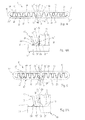
- Figures 4 and 5 two disrupters 17 are introduced into the internal channels 16 of the thin wall 10 thus folded, instead of the single disruptor 17 described in connection with the figure 2 .
- These disruptors 17 are substantially identical and are usually obtained from a metal foil which is worked to take in this case a sinusoidal wave form with a simple network of folds 21, so that the vertices 20 of the parallel folds 21 touch the inner face 11 of the folded wall 10 extending parallel along the tube 6.
- these two disrupters 17 serve to improve the thermal performance and the mechanical strength (resist the pressure of the refrigerant in the condenser).
- the materials used for the thin wall 10 and the interferers 17 are generally identical aluminum alloys and on them (thin wall and disturbing) are deposited unrepresented cladding coatings for subsequent brazing in an oven.
- the adjacent end legs 15 of the thin wall 10 extend as far as their lateral edges 19, substantially in contact with the inner face 11 of the base part 12.
- the end folds 22 'of the disturbers 17 housed in the longitudinal channels 16 also come substantially into contact with the end legs 15 and the part of concerned base 12, so as to form a connecting reinforcement 24 'between the end legs 15 and the base portion 12.
- Each end fold 22 'constituting the connecting reinforcement 24' has, in the example of the Figures 4 and 4A , a form of rounded fillet 25 'simply corresponding to the beginning of the sinusoidal profile, and extending between the free end leg 15 and the base part 12.
- the longitudinal free edge 26' of the fillet 25 ' is for example at the less than one-third of the leg relative to its edge, to thus ensure a correct longitudinal support and the rounded shape of the fillet delimits, with the leg and the base portion perpendicular to each other, a clearance or longitudinal empty space 27 '.
- each reinforcing end fold 22 'with the leg 15 and the base part 12 is done by soldering, during the passage of the mounted condenser (tubes with integrated disturbers and manifolds) in the oven provided for this effect.
- the unrepresented cladding coatings intended for brazing are deposited either wholly or partially on the two corrugated faces of the disruptor and / or on the internal face of the folded wall forming the tube.
- the side slices 19 terminating the adjacent end legs 15 of the bent tube 6 are spaced from the inner face 11 of the base portion 12.
- the spacing distance then substantially corresponds to the wall thickness e of the disrupter 40 and in particular at the flat central connecting portion 34 'thereof joining the two identical networks 31' of corrugated folds 32 '.
- the introduction of the one-piece disruptor 40 'to two networks 31' can be done by engaging the central connecting portion 34 'in the gap left between the slices 19 of the legs 15 and the inner face 11 of the base portion 12 of the tube 6.
- the two networks 31 ' engage simultaneously and completely in the oblong channels 16, as previously, with the vertices 35' of the folds 32 'cooperating with the inner face 11 of the base portion 12 and the relevant top portions 14 .
- the width of the central connecting portion 34 corresponds substantially to the sum of the thicknesses of the two adjacent legs 15.
Landscapes
- Engineering & Computer Science (AREA)
- Mechanical Engineering (AREA)
- Physics & Mathematics (AREA)
- Thermal Sciences (AREA)
- General Engineering & Computer Science (AREA)
- Geometry (AREA)
- Heat-Exchange Devices With Radiators And Conduit Assemblies (AREA)
- Air-Conditioning For Vehicles (AREA)
Priority Applications (1)
| Application Number | Priority Date | Filing Date | Title |
|---|---|---|---|
| PL14152354T PL2725317T3 (pl) | 2010-06-30 | 2011-06-21 | Rurka wymiennika ciepła oraz wymiennik ciepła zawierający taką rurkę |
Applications Claiming Priority (4)
| Application Number | Priority Date | Filing Date | Title |
|---|---|---|---|
| FR1002767A FR2962202B1 (fr) | 2010-06-30 | 2010-06-30 | Tube pour echangeur de chaleur et echangeur de chaleur equipe d'un tel tube |
| FR1002773A FR2962203B1 (fr) | 2010-06-30 | 2010-06-30 | Tube pour echangeur de chaleur et echangeur de chaleur equipe d'un tel tube |
| PCT/EP2011/060351 WO2012000842A2 (fr) | 2010-06-30 | 2011-06-21 | Tube de circulation de fluide et echangeur de chaleur comportant de tels tubes |
| EP11726789.8A EP2588824B1 (de) | 2010-06-30 | 2011-06-21 | Flüssigkeitszirkulationsrohr für einen wärmetauscher und wärmetauscher mit derartigen rohren |
Related Parent Applications (2)
| Application Number | Title | Priority Date | Filing Date |
|---|---|---|---|
| EP11726789.8A Division EP2588824B1 (de) | 2010-06-30 | 2011-06-21 | Flüssigkeitszirkulationsrohr für einen wärmetauscher und wärmetauscher mit derartigen rohren |
| EP11726789.8A Division-Into EP2588824B1 (de) | 2010-06-30 | 2011-06-21 | Flüssigkeitszirkulationsrohr für einen wärmetauscher und wärmetauscher mit derartigen rohren |
Publications (2)
| Publication Number | Publication Date |
|---|---|
| EP2725317A1 true EP2725317A1 (de) | 2014-04-30 |
| EP2725317B1 EP2725317B1 (de) | 2021-04-21 |
Family
ID=43757841
Family Applications (3)
| Application Number | Title | Priority Date | Filing Date |
|---|---|---|---|
| EP11728213.7A Withdrawn EP2588825A2 (de) | 2010-06-30 | 2011-06-14 | Wärmetauscherrohr, wärmetauscher mit derartigen rohren und verfahren zur herstellung eines derartigen rohrs |
| EP14152354.8A Active EP2725317B1 (de) | 2010-06-30 | 2011-06-21 | Wärmetauscherrohr und Wärmetauscher umfassend das entsprechende Rohr |
| EP11726789.8A Active EP2588824B1 (de) | 2010-06-30 | 2011-06-21 | Flüssigkeitszirkulationsrohr für einen wärmetauscher und wärmetauscher mit derartigen rohren |
Family Applications Before (1)
| Application Number | Title | Priority Date | Filing Date |
|---|---|---|---|
| EP11728213.7A Withdrawn EP2588825A2 (de) | 2010-06-30 | 2011-06-14 | Wärmetauscherrohr, wärmetauscher mit derartigen rohren und verfahren zur herstellung eines derartigen rohrs |
Family Applications After (1)
| Application Number | Title | Priority Date | Filing Date |
|---|---|---|---|
| EP11726789.8A Active EP2588824B1 (de) | 2010-06-30 | 2011-06-21 | Flüssigkeitszirkulationsrohr für einen wärmetauscher und wärmetauscher mit derartigen rohren |
Country Status (8)
| Country | Link |
|---|---|
| US (3) | US20130192811A1 (de) |
| EP (3) | EP2588825A2 (de) |
| JP (2) | JP6069194B2 (de) |
| KR (3) | KR20130098292A (de) |
| CN (2) | CN103080685B (de) |
| FR (1) | FR2962204B1 (de) |
| PL (2) | PL2725317T3 (de) |
| WO (2) | WO2012000779A2 (de) |
Families Citing this family (24)
| Publication number | Priority date | Publication date | Assignee | Title |
|---|---|---|---|---|
| FR2962204B1 (fr) | 2010-06-30 | 2014-11-21 | Valeo Systemes Thermiques | Tube d'echangeur de chaleur, echangeur de chaleur comportant de tels tubes et procede d'obtention d'un tel tube. |
| FR2973490B1 (fr) * | 2011-03-31 | 2018-05-18 | Valeo Systemes Thermiques | Tube pour echangeur thermique, echangeur thermique et procede d'obtention correspondants |
| FR2986314A1 (fr) * | 2012-01-31 | 2013-08-02 | Valeo Systemes Thermiques | Tube d'echangeur thermique, echangeur thermique et procede d'obtention correspondant |
| US9194389B2 (en) * | 2012-10-10 | 2015-11-24 | Tricore Corporation | Highly airtight gas pump |
| CN104792210A (zh) * | 2014-01-16 | 2015-07-22 | 泰安鼎鑫冷却器有限公司 | 三部件组合散热管 |
| WO2015126105A1 (ko) * | 2014-02-21 | 2015-08-27 | 한라비스테온공조 주식회사 | 열교환기용 튜브 |
| DE112015000904T5 (de) * | 2014-02-21 | 2016-11-17 | Hanon Systems | Rohr für Wärmetauscher |
| KR102191901B1 (ko) * | 2014-03-05 | 2020-12-17 | 한온시스템 주식회사 | 열교환기용 튜브 |
| KR102189621B1 (ko) * | 2015-01-29 | 2020-12-11 | 한온시스템 주식회사 | 열교환기용 튜브 |
| JP6170016B2 (ja) * | 2014-06-18 | 2017-07-26 | 株式会社ユタカ技研 | 熱交換器用フィンケースの製造方法 |
| CN105484853B (zh) * | 2014-09-17 | 2018-07-06 | 泰安鼎鑫冷却器有限公司 | 一种双波内翅片结构中冷器 |
| CN104668921A (zh) * | 2014-12-15 | 2015-06-03 | 上海德尔福汽车空调系统有限公司 | 可随炉钎焊的折叠式散热管及其生产方法 |
| KR102371382B1 (ko) * | 2015-07-24 | 2022-03-08 | 한온시스템 주식회사 | 열교환기용 튜브 |
| NL2015996B1 (en) * | 2015-12-21 | 2017-06-30 | Recair Holding B V | Heat exchanger. |
| CN106949769A (zh) * | 2016-01-07 | 2017-07-14 | 上海交通大学 | 组合式折叠热交换扁管 |
| KR102289749B1 (ko) * | 2017-05-10 | 2021-08-13 | 현대모비스 주식회사 | 열교환기용 튜브 |
| DE102018111585A1 (de) * | 2017-06-22 | 2018-12-27 | Hanon Systems | Vorrichtung zur Wärmeübertragung sowie Verfahren zum Herstellen der Vorrichtung |
| US20200088474A1 (en) * | 2018-09-13 | 2020-03-19 | Denso International America, Inc. | Impact resistant structural radiator tube |
| EP3650799B1 (de) * | 2018-11-07 | 2021-12-15 | Borgwarner Emissions Systems Spain, S.L.U. | Rippenkörper für ein wärmetauscherrohr |
| KR102660499B1 (ko) | 2019-01-08 | 2024-04-24 | 현대모비스 주식회사 | 열관리장치의 튜브 어셈블리 및 그 제조방법 |
| KR102174251B1 (ko) * | 2019-06-14 | 2020-11-04 | 한온시스템 주식회사 | 열교환기 |
| CN112103421B (zh) * | 2019-06-18 | 2021-10-22 | 宁德时代新能源科技股份有限公司 | 温控组件及电池包 |
| FR3112847A1 (fr) * | 2020-07-27 | 2022-01-28 | Valeo Systemes Thermiques | Dispositif de régulation thermique, notamment de refroidissement pour véhicule automobile |
| LU500125B1 (en) | 2021-05-05 | 2022-11-08 | Estra Automotive Systems Luxembourg S A R L | Exchanger tube for a heat exchanger |
Citations (6)
| Publication number | Priority date | Publication date | Assignee | Title |
|---|---|---|---|---|
| JP2000329488A (ja) * | 1999-05-20 | 2000-11-30 | Toyo Radiator Co Ltd | 熱交換器用偏平チューブ |
| US20020038500A1 (en) * | 2000-07-25 | 2002-04-04 | Mando Climate Control Corporation | Method and apparatus for manufacturing coolant tube of heat exchanger |
| EP1243884A2 (de) * | 2001-03-22 | 2002-09-25 | Delphi Technologies, Inc. | Wärmetauscherrohr |
| FR2836546A1 (fr) * | 2002-02-22 | 2003-08-29 | Valeo Thermique Moteur Sa | Tube plie poue echangeur de chaleur |
| JP2003302186A (ja) * | 2002-04-05 | 2003-10-24 | Zexel Valeo Climate Control Corp | 熱交換器用チューブ及びその製造方法並びに熱交換器 |
| WO2006015029A2 (en) * | 2004-07-28 | 2006-02-09 | Valeo, Inc. | Automotive heat exchanger assemblies having internal fins and methods of making the same |
Family Cites Families (27)
| Publication number | Priority date | Publication date | Assignee | Title |
|---|---|---|---|---|
| US2912749A (en) * | 1956-01-13 | 1959-11-17 | Modine Mfg Co | Method of making a heat exchanger |
| GB1149923A (en) * | 1966-07-01 | 1969-04-23 | Karl Sten Bertil Lundberg | Improvements in or relating to methods of manufacturing lamellae for heat exchangers |
| JPS6167531A (ja) * | 1984-09-07 | 1986-04-07 | Showa Alum Corp | インナ−フインを備えた熱交換管の製造法 |
| JPH04129678U (ja) * | 1991-04-30 | 1992-11-27 | 日野自動車工業株式会社 | インタークーラ |
| JPH0552565U (ja) * | 1991-12-20 | 1993-07-13 | サンデン株式会社 | 熱交換器 |
| FR2690513B1 (fr) * | 1992-04-24 | 1994-07-29 | Valeo Thermique Moteur Sa | Tube de section allongee pour echangeur de chaleur, notamment de vehicule automobile, et echangeur de chaleur comprenant de tels tubes. |
| GB2268260A (en) * | 1992-06-24 | 1994-01-05 | Llanelli Radiators Ltd | Heat exchange tubes formed from a unitary portion of sheet or strip material |
| US5579837A (en) * | 1995-11-15 | 1996-12-03 | Ford Motor Company | Heat exchanger tube and method of making the same |
| JP3799671B2 (ja) * | 1996-08-07 | 2006-07-19 | 株式会社デンソー | 熱交換器、熱交換器用チューブ及び熱交換器の製造方法 |
| US5934365A (en) * | 1997-08-21 | 1999-08-10 | Ford Motor Company | Heat exchanger |
| US6192977B1 (en) | 1999-09-29 | 2001-02-27 | Valeo Thermique Moteur | Tube for heat exchanger |
| FR2803378B1 (fr) * | 1999-12-29 | 2004-03-19 | Valeo Climatisation | Echangeur de chaleur a tubes a plusieurs canaux, en particulier pour vehicule automobile |
| JP2001263976A (ja) * | 2000-03-15 | 2001-09-26 | Zexel Valeo Climate Control Corp | 熱交換器 |
| FR2823840B1 (fr) * | 2001-04-20 | 2004-01-23 | Valeo Thermique Moteur Sa | Tube plie pour echangeur de chaleur et procede pour sa conformation |
| JP2004333023A (ja) * | 2003-05-08 | 2004-11-25 | Toyo Radiator Co Ltd | アルミニューム製熱交換器用偏平チューブ |
| DE10328001A1 (de) * | 2003-06-21 | 2005-01-05 | Modine Manufacturing Co., Racine | Flaches Wärmetauscherrohr |
| DE102004049809A1 (de) * | 2004-10-12 | 2006-04-13 | Behr Gmbh & Co. Kg | Flachrohr für Wärmetauscher |
| US7182128B2 (en) * | 2005-03-09 | 2007-02-27 | Visteon Global Technologies, Inc. | Heat exchanger tube having strengthening deformations |
| DE102005013777A1 (de) * | 2005-03-22 | 2006-09-28 | Behr Gmbh & Co. Kg | Rohr für einen Wärmetauscher |
| DE102005043093A1 (de) | 2005-09-10 | 2007-03-15 | Modine Manufacturing Co., Racine | Wärmetauscherrohr |
| JP2007178010A (ja) * | 2005-12-27 | 2007-07-12 | Calsonic Kansei Corp | 熱交換器用インナーフィン |
| US7921559B2 (en) * | 2006-01-19 | 2011-04-12 | Modine Manufacturing Company | Flat tube, flat tube heat exchanger, and method of manufacturing same |
| DE102006006670B4 (de) | 2006-02-14 | 2014-02-13 | Modine Manufacturing Co. | Flachrohr für Wärmetauscher |
| JP2007298201A (ja) * | 2006-04-28 | 2007-11-15 | Denso Corp | 熱交換器、加工装置および熱交換器の製造方法 |
| DE102007039292A1 (de) * | 2007-08-20 | 2009-02-26 | Behr Gmbh & Co. Kg | Mehrkammer-Flachrohr, Wärmetauscher und Verwendung eines Wärmetauschers |
| JP2010008018A (ja) * | 2008-06-30 | 2010-01-14 | Showa Denko Kk | インナーフィン付き熱交換管およびこれを用いた熱交換器 |
| FR2962204B1 (fr) | 2010-06-30 | 2014-11-21 | Valeo Systemes Thermiques | Tube d'echangeur de chaleur, echangeur de chaleur comportant de tels tubes et procede d'obtention d'un tel tube. |
-
2010
- 2010-12-02 FR FR1060044A patent/FR2962204B1/fr not_active Expired - Fee Related
-
2011
- 2011-06-14 JP JP2013517150A patent/JP6069194B2/ja not_active Expired - Fee Related
- 2011-06-14 EP EP11728213.7A patent/EP2588825A2/de not_active Withdrawn
- 2011-06-14 WO PCT/EP2011/059825 patent/WO2012000779A2/fr not_active Ceased
- 2011-06-14 CN CN201180041851.5A patent/CN103080685B/zh not_active Expired - Fee Related
- 2011-06-14 KR KR1020137002436A patent/KR20130098292A/ko not_active Ceased
- 2011-06-14 US US13/807,478 patent/US20130192811A1/en not_active Abandoned
- 2011-06-21 EP EP14152354.8A patent/EP2725317B1/de active Active
- 2011-06-21 PL PL14152354T patent/PL2725317T3/pl unknown
- 2011-06-21 CN CN201180042119.XA patent/CN103080686B/zh active Active
- 2011-06-21 WO PCT/EP2011/060351 patent/WO2012000842A2/fr not_active Ceased
- 2011-06-21 KR KR1020187027790A patent/KR102018675B1/ko not_active Expired - Fee Related
- 2011-06-21 US US13/807,435 patent/US10987720B2/en not_active Expired - Fee Related
- 2011-06-21 EP EP11726789.8A patent/EP2588824B1/de active Active
- 2011-06-21 KR KR1020127034212A patent/KR20130100245A/ko not_active Ceased
- 2011-06-21 JP JP2013517178A patent/JP5837582B2/ja not_active Expired - Fee Related
- 2011-06-21 PL PL11726789T patent/PL2588824T3/pl unknown
-
2017
- 2017-02-08 US US15/427,757 patent/US20170144212A1/en not_active Abandoned
Patent Citations (6)
| Publication number | Priority date | Publication date | Assignee | Title |
|---|---|---|---|---|
| JP2000329488A (ja) * | 1999-05-20 | 2000-11-30 | Toyo Radiator Co Ltd | 熱交換器用偏平チューブ |
| US20020038500A1 (en) * | 2000-07-25 | 2002-04-04 | Mando Climate Control Corporation | Method and apparatus for manufacturing coolant tube of heat exchanger |
| EP1243884A2 (de) * | 2001-03-22 | 2002-09-25 | Delphi Technologies, Inc. | Wärmetauscherrohr |
| FR2836546A1 (fr) * | 2002-02-22 | 2003-08-29 | Valeo Thermique Moteur Sa | Tube plie poue echangeur de chaleur |
| JP2003302186A (ja) * | 2002-04-05 | 2003-10-24 | Zexel Valeo Climate Control Corp | 熱交換器用チューブ及びその製造方法並びに熱交換器 |
| WO2006015029A2 (en) * | 2004-07-28 | 2006-02-09 | Valeo, Inc. | Automotive heat exchanger assemblies having internal fins and methods of making the same |
Also Published As
| Publication number | Publication date |
|---|---|
| CN103080685B (zh) | 2015-05-06 |
| JP6069194B2 (ja) | 2017-02-01 |
| JP2013530373A (ja) | 2013-07-25 |
| KR102018675B1 (ko) | 2019-09-05 |
| US20140000853A1 (en) | 2014-01-02 |
| CN103080686B (zh) | 2016-03-02 |
| KR20180110189A (ko) | 2018-10-08 |
| EP2725317B1 (de) | 2021-04-21 |
| WO2012000779A2 (fr) | 2012-01-05 |
| WO2012000842A3 (fr) | 2013-01-10 |
| PL2725317T3 (pl) | 2021-08-23 |
| CN103080686A (zh) | 2013-05-01 |
| WO2012000842A2 (fr) | 2012-01-05 |
| CN103080685A (zh) | 2013-05-01 |
| EP2588824B1 (de) | 2019-07-31 |
| JP5837582B2 (ja) | 2015-12-24 |
| FR2962204B1 (fr) | 2014-11-21 |
| EP2588825A2 (de) | 2013-05-08 |
| US20130192811A1 (en) | 2013-08-01 |
| US20170144212A1 (en) | 2017-05-25 |
| KR20130098292A (ko) | 2013-09-04 |
| KR20130100245A (ko) | 2013-09-10 |
| FR2962204A1 (fr) | 2012-01-06 |
| PL2588824T3 (pl) | 2020-06-01 |
| WO2012000779A3 (fr) | 2012-10-18 |
| JP2013536390A (ja) | 2013-09-19 |
| EP2588824A2 (de) | 2013-05-08 |
| US10987720B2 (en) | 2021-04-27 |
Similar Documents
| Publication | Publication Date | Title |
|---|---|---|
| EP2588824B1 (de) | Flüssigkeitszirkulationsrohr für einen wärmetauscher und wärmetauscher mit derartigen rohren | |
| WO2012160054A1 (fr) | Boite collectrice, echangeur de chaleur comprenant ladite boite collectrice et procede de sertissage d'une telle boite | |
| EP2912396B1 (de) | Wärmetauscher, insbesondere für ein kraftfahrzeug | |
| EP2691722B1 (de) | Wärmetauscherrohr und entsprechendes herstellungsverfahren für wärmetauscher | |
| EP3011252B1 (de) | Wärmetauscher, insbesondere für kraftfahrzeugklimaanlagenkreise oder -schaltungen | |
| FR2962202A1 (fr) | Tube pour echangeur de chaleur et echangeur de chaleur equipe d'un tel tube | |
| WO2010149452A1 (fr) | Bloc d'échangeur de chaleur, en particulier pour condenseur de climatisation | |
| FR2962203A1 (fr) | Tube pour echangeur de chaleur et echangeur de chaleur equipe d'un tel tube | |
| WO2007048888A1 (fr) | Echangeur de chaleur à tubes plats déformés par torsion | |
| EP2655000A1 (de) | Lötverfahren für einen wärmetauscher sowie entsprechendes rohr und wärmetauscher | |
| FR2832788A1 (fr) | Profils de tubes pour echangeur thermique | |
| WO2008061918A1 (fr) | Echangeur de chaleur interne pour circuit de fluide refrigerant | |
| FR2944591A1 (fr) | Tube de circulation de fluide refrigerant, faisceau d'echange de chaleur et echangeur de chaleur comportant de tels tubes | |
| EP1676088B1 (de) | Strömungselement für einen wärmetauscher und so erhaltener wärmetauscher | |
| EP1896213A1 (de) | Verfahren zum hartlöten eines gefalzten wärmetauscherrohrs unter zuführung eines flussmittels in der nähe einer kontaktzone der wände, sich ergebendes rohr | |
| WO2013127770A1 (fr) | Procédé de fabrication d'un tube d'échangeur de chaleur pour véhicule | |
| FR2924794A1 (fr) | Tubes multicanaux pour un echangeur de chaleur brase | |
| EP1978325B1 (de) | Seitenteil mit Abschwächungszone für Wärmetauscher | |
| EP1649231B1 (de) | Rohrverschluss für ein element eines hydraulischen kreises, insbesondere für einen wärmetauscher | |
| EP2810008A1 (de) | Wärmetauscherrohr, wärmetauscher und herstellungsverfahren dafür | |
| EP2729751A1 (de) | Wärmetauscherrohr und wärmetauscher mit solchen rohren | |
| FR2968754A1 (fr) | Tube d'echangeur de chaleur, echangeur de chaleur comportant de tels tubes et procede d'obtention d'un tel tube. | |
| WO2015007551A1 (fr) | Plaque collectrice de collecteur d'un echangeur de chaleur | |
| FR2986314A1 (fr) | Tube d'echangeur thermique, echangeur thermique et procede d'obtention correspondant | |
| EP1623177A2 (de) | Wärmetauscher, insbesondere für kraftfahrzeuge |
Legal Events
| Date | Code | Title | Description |
|---|---|---|---|
| PUAI | Public reference made under article 153(3) epc to a published international application that has entered the european phase |
Free format text: ORIGINAL CODE: 0009012 |
|
| 17P | Request for examination filed |
Effective date: 20140123 |
|
| AC | Divisional application: reference to earlier application |
Ref document number: 2588824 Country of ref document: EP Kind code of ref document: P |
|
| AK | Designated contracting states |
Kind code of ref document: A1 Designated state(s): AL AT BE BG CH CY CZ DE DK EE ES FI FR GB GR HR HU IE IS IT LI LT LU LV MC MK MT NL NO PL PT RO RS SE SI SK SM TR |
|
| 17P | Request for examination filed |
Effective date: 20141029 |
|
| RBV | Designated contracting states (corrected) |
Designated state(s): AL AT BE BG CH CY CZ DE DK EE ES FI FR GB GR HR HU IE IS IT LI LT LU LV MC MK MT NL NO PL PT RO RS SE SI SK SM TR |
|
| STAA | Information on the status of an ep patent application or granted ep patent |
Free format text: STATUS: EXAMINATION IS IN PROGRESS |
|
| 17Q | First examination report despatched |
Effective date: 20161031 |
|
| GRAP | Despatch of communication of intention to grant a patent |
Free format text: ORIGINAL CODE: EPIDOSNIGR1 |
|
| STAA | Information on the status of an ep patent application or granted ep patent |
Free format text: STATUS: GRANT OF PATENT IS INTENDED |
|
| RIC1 | Information provided on ipc code assigned before grant |
Ipc: F28F 1/02 20060101ALN20201020BHEP Ipc: F28F 3/02 20060101ALI20201020BHEP Ipc: F28F 1/40 20060101ALI20201020BHEP Ipc: F28F 3/12 20060101ALN20201020BHEP Ipc: B21D 53/06 20060101ALN20201020BHEP Ipc: F28D 1/03 20060101AFI20201020BHEP Ipc: B23P 15/26 20060101ALN20201020BHEP Ipc: F28F 13/12 20060101ALI20201020BHEP Ipc: B21C 37/22 20060101ALN20201020BHEP |
|
| RIC1 | Information provided on ipc code assigned before grant |
Ipc: F28F 1/02 20060101ALN20201028BHEP Ipc: F28F 3/02 20060101ALI20201028BHEP Ipc: B23P 15/26 20060101ALN20201028BHEP Ipc: F28F 1/40 20060101ALI20201028BHEP Ipc: F28F 3/12 20060101ALN20201028BHEP Ipc: B21D 53/06 20060101ALN20201028BHEP Ipc: B21C 37/22 20060101ALN20201028BHEP Ipc: F28D 1/03 20060101AFI20201028BHEP Ipc: F28F 13/12 20060101ALI20201028BHEP |
|
| INTG | Intention to grant announced |
Effective date: 20201110 |
|
| GRAS | Grant fee paid |
Free format text: ORIGINAL CODE: EPIDOSNIGR3 |
|
| GRAA | (expected) grant |
Free format text: ORIGINAL CODE: 0009210 |
|
| STAA | Information on the status of an ep patent application or granted ep patent |
Free format text: STATUS: THE PATENT HAS BEEN GRANTED |
|
| AC | Divisional application: reference to earlier application |
Ref document number: 2588824 Country of ref document: EP Kind code of ref document: P |
|
| AK | Designated contracting states |
Kind code of ref document: B1 Designated state(s): AL AT BE BG CH CY CZ DE DK EE ES FI FR GB GR HR HU IE IS IT LI LT LU LV MC MK MT NL NO PL PT RO RS SE SI SK SM TR |
|
| REG | Reference to a national code |
Ref country code: GB Ref legal event code: FG4D Free format text: NOT ENGLISH |
|
| REG | Reference to a national code |
Ref country code: CH Ref legal event code: EP |
|
| REG | Reference to a national code |
Ref country code: DE Ref legal event code: R096 Ref document number: 602011070781 Country of ref document: DE |
|
| REG | Reference to a national code |
Ref country code: IE Ref legal event code: FG4D Free format text: LANGUAGE OF EP DOCUMENT: FRENCH |
|
| REG | Reference to a national code |
Ref country code: AT Ref legal event code: REF Ref document number: 1385070 Country of ref document: AT Kind code of ref document: T Effective date: 20210515 |
|
| REG | Reference to a national code |
Ref country code: LT Ref legal event code: MG9D |
|
| REG | Reference to a national code |
Ref country code: AT Ref legal event code: MK05 Ref document number: 1385070 Country of ref document: AT Kind code of ref document: T Effective date: 20210421 |
|
| REG | Reference to a national code |
Ref country code: NL Ref legal event code: MP Effective date: 20210421 |
|
| PG25 | Lapsed in a contracting state [announced via postgrant information from national office to epo] |
Ref country code: FI Free format text: LAPSE BECAUSE OF FAILURE TO SUBMIT A TRANSLATION OF THE DESCRIPTION OR TO PAY THE FEE WITHIN THE PRESCRIBED TIME-LIMIT Effective date: 20210421 Ref country code: NL Free format text: LAPSE BECAUSE OF FAILURE TO SUBMIT A TRANSLATION OF THE DESCRIPTION OR TO PAY THE FEE WITHIN THE PRESCRIBED TIME-LIMIT Effective date: 20210421 Ref country code: LT Free format text: LAPSE BECAUSE OF FAILURE TO SUBMIT A TRANSLATION OF THE DESCRIPTION OR TO PAY THE FEE WITHIN THE PRESCRIBED TIME-LIMIT Effective date: 20210421 Ref country code: AT Free format text: LAPSE BECAUSE OF FAILURE TO SUBMIT A TRANSLATION OF THE DESCRIPTION OR TO PAY THE FEE WITHIN THE PRESCRIBED TIME-LIMIT Effective date: 20210421 Ref country code: BG Free format text: LAPSE BECAUSE OF FAILURE TO SUBMIT A TRANSLATION OF THE DESCRIPTION OR TO PAY THE FEE WITHIN THE PRESCRIBED TIME-LIMIT Effective date: 20210721 Ref country code: HR Free format text: LAPSE BECAUSE OF FAILURE TO SUBMIT A TRANSLATION OF THE DESCRIPTION OR TO PAY THE FEE WITHIN THE PRESCRIBED TIME-LIMIT Effective date: 20210421 |
|
| PG25 | Lapsed in a contracting state [announced via postgrant information from national office to epo] |
Ref country code: LV Free format text: LAPSE BECAUSE OF FAILURE TO SUBMIT A TRANSLATION OF THE DESCRIPTION OR TO PAY THE FEE WITHIN THE PRESCRIBED TIME-LIMIT Effective date: 20210421 Ref country code: GR Free format text: LAPSE BECAUSE OF FAILURE TO SUBMIT A TRANSLATION OF THE DESCRIPTION OR TO PAY THE FEE WITHIN THE PRESCRIBED TIME-LIMIT Effective date: 20210722 Ref country code: IS Free format text: LAPSE BECAUSE OF FAILURE TO SUBMIT A TRANSLATION OF THE DESCRIPTION OR TO PAY THE FEE WITHIN THE PRESCRIBED TIME-LIMIT Effective date: 20210821 Ref country code: RS Free format text: LAPSE BECAUSE OF FAILURE TO SUBMIT A TRANSLATION OF THE DESCRIPTION OR TO PAY THE FEE WITHIN THE PRESCRIBED TIME-LIMIT Effective date: 20210421 Ref country code: SE Free format text: LAPSE BECAUSE OF FAILURE TO SUBMIT A TRANSLATION OF THE DESCRIPTION OR TO PAY THE FEE WITHIN THE PRESCRIBED TIME-LIMIT Effective date: 20210421 Ref country code: PT Free format text: LAPSE BECAUSE OF FAILURE TO SUBMIT A TRANSLATION OF THE DESCRIPTION OR TO PAY THE FEE WITHIN THE PRESCRIBED TIME-LIMIT Effective date: 20210823 Ref country code: NO Free format text: LAPSE BECAUSE OF FAILURE TO SUBMIT A TRANSLATION OF THE DESCRIPTION OR TO PAY THE FEE WITHIN THE PRESCRIBED TIME-LIMIT Effective date: 20210721 Ref country code: ES Free format text: LAPSE BECAUSE OF FAILURE TO SUBMIT A TRANSLATION OF THE DESCRIPTION OR TO PAY THE FEE WITHIN THE PRESCRIBED TIME-LIMIT Effective date: 20210421 |
|
| PGFP | Annual fee paid to national office [announced via postgrant information from national office to epo] |
Ref country code: PL Payment date: 20210806 Year of fee payment: 11 |
|
| REG | Reference to a national code |
Ref country code: DE Ref legal event code: R097 Ref document number: 602011070781 Country of ref document: DE |
|
| PG25 | Lapsed in a contracting state [announced via postgrant information from national office to epo] |
Ref country code: SK Free format text: LAPSE BECAUSE OF FAILURE TO SUBMIT A TRANSLATION OF THE DESCRIPTION OR TO PAY THE FEE WITHIN THE PRESCRIBED TIME-LIMIT Effective date: 20210421 Ref country code: SM Free format text: LAPSE BECAUSE OF FAILURE TO SUBMIT A TRANSLATION OF THE DESCRIPTION OR TO PAY THE FEE WITHIN THE PRESCRIBED TIME-LIMIT Effective date: 20210421 Ref country code: CZ Free format text: LAPSE BECAUSE OF FAILURE TO SUBMIT A TRANSLATION OF THE DESCRIPTION OR TO PAY THE FEE WITHIN THE PRESCRIBED TIME-LIMIT Effective date: 20210421 Ref country code: DK Free format text: LAPSE BECAUSE OF FAILURE TO SUBMIT A TRANSLATION OF THE DESCRIPTION OR TO PAY THE FEE WITHIN THE PRESCRIBED TIME-LIMIT Effective date: 20210421 Ref country code: EE Free format text: LAPSE BECAUSE OF FAILURE TO SUBMIT A TRANSLATION OF THE DESCRIPTION OR TO PAY THE FEE WITHIN THE PRESCRIBED TIME-LIMIT Effective date: 20210421 Ref country code: RO Free format text: LAPSE BECAUSE OF FAILURE TO SUBMIT A TRANSLATION OF THE DESCRIPTION OR TO PAY THE FEE WITHIN THE PRESCRIBED TIME-LIMIT Effective date: 20210421 Ref country code: MC Free format text: LAPSE BECAUSE OF FAILURE TO SUBMIT A TRANSLATION OF THE DESCRIPTION OR TO PAY THE FEE WITHIN THE PRESCRIBED TIME-LIMIT Effective date: 20210421 |
|
| REG | Reference to a national code |
Ref country code: CH Ref legal event code: PL |
|
| PLBE | No opposition filed within time limit |
Free format text: ORIGINAL CODE: 0009261 |
|
| STAA | Information on the status of an ep patent application or granted ep patent |
Free format text: STATUS: NO OPPOSITION FILED WITHIN TIME LIMIT |
|
| REG | Reference to a national code |
Ref country code: BE Ref legal event code: MM Effective date: 20210630 |
|
| GBPC | Gb: european patent ceased through non-payment of renewal fee |
Effective date: 20210721 |
|
| 26N | No opposition filed |
Effective date: 20220124 |
|
| PG25 | Lapsed in a contracting state [announced via postgrant information from national office to epo] |
Ref country code: LU Free format text: LAPSE BECAUSE OF NON-PAYMENT OF DUE FEES Effective date: 20210621 |
|
| PG25 | Lapsed in a contracting state [announced via postgrant information from national office to epo] |
Ref country code: LI Free format text: LAPSE BECAUSE OF NON-PAYMENT OF DUE FEES Effective date: 20210630 Ref country code: IE Free format text: LAPSE BECAUSE OF NON-PAYMENT OF DUE FEES Effective date: 20210621 Ref country code: GB Free format text: LAPSE BECAUSE OF NON-PAYMENT OF DUE FEES Effective date: 20210721 Ref country code: CH Free format text: LAPSE BECAUSE OF NON-PAYMENT OF DUE FEES Effective date: 20210630 |
|
| PG25 | Lapsed in a contracting state [announced via postgrant information from national office to epo] |
Ref country code: IS Free format text: LAPSE BECAUSE OF FAILURE TO SUBMIT A TRANSLATION OF THE DESCRIPTION OR TO PAY THE FEE WITHIN THE PRESCRIBED TIME-LIMIT Effective date: 20210821 Ref country code: AL Free format text: LAPSE BECAUSE OF FAILURE TO SUBMIT A TRANSLATION OF THE DESCRIPTION OR TO PAY THE FEE WITHIN THE PRESCRIBED TIME-LIMIT Effective date: 20210421 |
|
| PG25 | Lapsed in a contracting state [announced via postgrant information from national office to epo] |
Ref country code: IT Free format text: LAPSE BECAUSE OF FAILURE TO SUBMIT A TRANSLATION OF THE DESCRIPTION OR TO PAY THE FEE WITHIN THE PRESCRIBED TIME-LIMIT Effective date: 20210421 Ref country code: BE Free format text: LAPSE BECAUSE OF NON-PAYMENT OF DUE FEES Effective date: 20210630 |
|
| PG25 | Lapsed in a contracting state [announced via postgrant information from national office to epo] |
Ref country code: HU Free format text: LAPSE BECAUSE OF FAILURE TO SUBMIT A TRANSLATION OF THE DESCRIPTION OR TO PAY THE FEE WITHIN THE PRESCRIBED TIME-LIMIT; INVALID AB INITIO Effective date: 20110621 Ref country code: CY Free format text: LAPSE BECAUSE OF FAILURE TO SUBMIT A TRANSLATION OF THE DESCRIPTION OR TO PAY THE FEE WITHIN THE PRESCRIBED TIME-LIMIT Effective date: 20210421 |
|
| P01 | Opt-out of the competence of the unified patent court (upc) registered |
Effective date: 20230528 |
|
| PG25 | Lapsed in a contracting state [announced via postgrant information from national office to epo] |
Ref country code: MK Free format text: LAPSE BECAUSE OF FAILURE TO SUBMIT A TRANSLATION OF THE DESCRIPTION OR TO PAY THE FEE WITHIN THE PRESCRIBED TIME-LIMIT Effective date: 20210421 |
|
| PG25 | Lapsed in a contracting state [announced via postgrant information from national office to epo] |
Ref country code: PL Free format text: LAPSE BECAUSE OF NON-PAYMENT OF DUE FEES Effective date: 20220621 |
|
| PGFP | Annual fee paid to national office [announced via postgrant information from national office to epo] |
Ref country code: DE Payment date: 20240613 Year of fee payment: 14 |
|
| PGFP | Annual fee paid to national office [announced via postgrant information from national office to epo] |
Ref country code: FR Payment date: 20240625 Year of fee payment: 14 |
|
| PG25 | Lapsed in a contracting state [announced via postgrant information from national office to epo] |
Ref country code: MT Free format text: LAPSE BECAUSE OF FAILURE TO SUBMIT A TRANSLATION OF THE DESCRIPTION OR TO PAY THE FEE WITHIN THE PRESCRIBED TIME-LIMIT Effective date: 20210421 |
|
| PG25 | Lapsed in a contracting state [announced via postgrant information from national office to epo] |
Ref country code: TR Free format text: LAPSE BECAUSE OF FAILURE TO SUBMIT A TRANSLATION OF THE DESCRIPTION OR TO PAY THE FEE WITHIN THE PRESCRIBED TIME-LIMIT Effective date: 20210421 |
|
| REG | Reference to a national code |
Ref country code: DE Ref legal event code: R119 Ref document number: 602011070781 Country of ref document: DE |
|
| PG25 | Lapsed in a contracting state [announced via postgrant information from national office to epo] |
Ref country code: DE Free format text: LAPSE BECAUSE OF NON-PAYMENT OF DUE FEES Effective date: 20260101 |
|
| PG25 | Lapsed in a contracting state [announced via postgrant information from national office to epo] |
Ref country code: FR Free format text: LAPSE BECAUSE OF NON-PAYMENT OF DUE FEES Effective date: 20250630 |