EP2725824A1 - Système pour détecter l'utilisation d'un téléphone sans fil dans un véhicule automobile - Google Patents
Système pour détecter l'utilisation d'un téléphone sans fil dans un véhicule automobile Download PDFInfo
- Publication number
- EP2725824A1 EP2725824A1 EP13183098.6A EP13183098A EP2725824A1 EP 2725824 A1 EP2725824 A1 EP 2725824A1 EP 13183098 A EP13183098 A EP 13183098A EP 2725824 A1 EP2725824 A1 EP 2725824A1
- Authority
- EP
- European Patent Office
- Prior art keywords
- vehicle
- wireless phone
- controller
- response
- wireless
- Prior art date
- Legal status (The legal status is an assumption and is not a legal conclusion. Google has not performed a legal analysis and makes no representation as to the accuracy of the status listed.)
- Granted
Links
Images


Classifications
-
- H—ELECTRICITY
- H04—ELECTRIC COMMUNICATION TECHNIQUE
- H04W—WIRELESS COMMUNICATION NETWORKS
- H04W4/00—Services specially adapted for wireless communication networks; Facilities therefor
- H04W4/50—Service provisioning or reconfiguring
-
- H—ELECTRICITY
- H04—ELECTRIC COMMUNICATION TECHNIQUE
- H04W—WIRELESS COMMUNICATION NETWORKS
- H04W4/00—Services specially adapted for wireless communication networks; Facilities therefor
- H04W4/20—Services signaling; Auxiliary data signalling, i.e. transmitting data via a non-traffic channel
- H04W4/21—Services signaling; Auxiliary data signalling, i.e. transmitting data via a non-traffic channel for social networking applications
Definitions
- the invention relates to detecting usage of a wireless phone in an automobile.
- a vehicle comprises a detection module and a controller.
- the detection module includes a directional antenna and signal processing logic.
- the detection module is located within the vehicle, arranged with re spect to a driver region, and configured to detect a condition wherein a wireless phone is op erated within the driver region.
- the detection module generates an output indicative of the detected condition.
- the controller is configured to receive the output, and control the vehicle in response to the detected condition.
- various embodiments of the invention may include one or more additional features depending on the application.
- the controller is further configured to transmit a signal to disable the wireless phone in response to the detected condition.
- the controller is further configured to determine when the vehicle is in motion, and to transmit a signal to di sable the wireless phone in response to the detected condition when the vehicle is in motion.
- the controller is further configured to transmit an association request to the wireless phone in response to the detected condition a nd configured to receive a response from the wireless phone.
- the controller is further configured to associate with the wireless phone upon receipt of the response from the wireless phone.
- the controller is further configured to determ ine when the vehicle is in motion, and to transmit an association request to the wireless phone in response to the detected condition w hen the vehicle is in motion.
- the controller is further configured to receive a response from the wireless phone and ass ociate with the wireless phone upon receipt of the response from the wireless phone.
- the controller may be configured to, upon association of the controller with the wireless phone, permit a vehicle audio system to be utilized by the wireless phone during continued operation of the wireless phone.
- the directional antenna and signal processing logic may be arranged to detect the condition wherein the wireless phone is operated within the driver region by sensing radio frequency transmission power in the driver region a bove a predetermined threshold.
- embodiments of the invention relate to detecting usage of a wireless phone in an automobile.
- Various actions may be taken upon the detection, and the appropriate action may vary depending on the application.
- the controller is further configured to produce an output observable by the driver in response to the detected condition.
- the detection module may include a single directional antenna. In other embodiments, the detection module may include a plurality of directional antennas located at separated locations within the vehicle.
- a vehicle comprises a detection module including a directional antenna and signal processing logic.
- the detection module is located within the vehicle, arranged with respect to a driver region, and configured to detect a condition wherein a wireless phone is operated within the driver region, and to generate an output indicative of the detected condition.
- a controller is configured to receive the output, and control the vehicle in res ponse to the detected condition.
- the directional antenna and signal processing logic are arranged to detect the condition wherein the wireless phone is operated within the driver region by sensing radio frequency transmission power in the driver region above a predetermined threshold.
- the controller is further configured to perform at least one of (i) transmit a signal to disable the wireless phone in response to the detected condition, (ii) associate with the wireless phone in response to the detected condition.
- a vehicle comprises a detection module including a plural ity of directional antennas located at separated locations within the vehicle and signal processing logic.
- the detection module is located within the vehicle, arranged with respect to a driver region, and configured to detect a condition wherein a wireless phone is operated within the driver region, and to generate an output indic ative of the detected condition.
- a controller is configured to receive the output, and control the vehicle in res ponse to the detected condition.
- the directional antennas and signal processing logic are arranged to detect the condition wherein the wireless phone is operated within the driver region by sensing radio frequency transmission power in the driver region above a predetermined threshold .
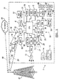
- Figure 1 illustrates an example block topology for a vehicle based computing system 1 (VCS) for a vehicle 31.
- VCS vehicle based computing system 1
- An example of such a vehicle -based computing system 1 is the SYNC system manufactured by THE FORD MOTOR COMPANY.
- a vehicle enabled with a vehicle-based computing system may contain a visual front end interface 4 located in the vehicle. The user may also be able to interact with the interface if it is provided, for example, with a touch sensitive screen. In another illustrative embodiment, the interaction occurs through, button pres ses, spoken dialog system with automatic speech recognition and speech synthesis.
- a processor 3 controls at least some portion of the operation of the vehicle -based computing system.
- the processor allows onboard processing of commands and routines.
- the processor is connected to both non -persistent 5 and persistent storage 7.
- the non-persistent storage is random access memory (RAM)
- the persistent storage is a hard disk drive (HDD) or flash memory.
- the processor 3 is also provided with a number of different inputs allowing the user to interface with the processor 3.
- a microphone 29, an auxiliary input 25 (for input 33), a USB input 23, a GPS input 24 and a BLUETOOTH input 15 are all provided.
- An input selector 51 is also provided, to allow a user to swap between various inputs. Input to both the microphone and the auxiliary connector is converted f rom analog to digital by a converter 27 before being passed to the processor.
- numerous of the vehicle components and auxiliary components in communication with the VCS may use a vehicle network (such as, but not limited to, a CAN bus) to pass data to and from the VCS (or components thereof).
- Outputs to the system can include, but are not limited to, a visual display 4 and a speaker 13 or stereo system output.
- the speaker is connected to an amplifier 11 and receives its signal from the processor 3 through a digital -to-analog converter 9.
- Output can also be made to a remote BLUETOOTH device such as PND 54 or a USB device such as vehicle navigation device 60 along the bi -directional data streams shown at 19 and 21 respectively.
- the system 1 uses the BLUETOOTH transceiver 15 to communicate 17 with a user's nomadic device 53 (e.g., cell phone, smart phone, PDA, or any other device having wireless remote network connectivity).
- the nomadic device can then be used to communicate 59 with a network 61 outside the vehicle 31 through, for example, communication 55 with a cellular tower 57.
- tower 57 may be a Wi-Fi access point.
- Exemplary communication between the nomadic device and the BLUETOO TH transceiver is represented by signal 14.
- Pairing a nomadic device 53 and the BLUETOOTH transceiver 15 can be instructed through a button 52 or similar input. Accordingly, the CPU is instructed that the onboard BLUETOOTH transceiver will be paired with a BLUETOOTH transceiver in a nomadic device.
- Data may be communicated between CPU 3 and network 61 utilizing, for example, a data - plan, data over voice, or DTMF tones associated with nomadic device 53.
- the nomadic device 53 can then be used to communicate 59 with a network 61 outside the vehicle 31 through, for example, communication 55 with a cellular tower 57.
- the modem 63 may establish communication 20 with the tower 57 for communicating with network 61.
- modem 63 may be a USB cellular modem and communication 20 may be cellular communication.
- the processor is provided with an operating system including an API to communicate with modem application software.
- the modem application software may access an embedded module or firmware on the BLUETOOTH transceiver to complete wireless communication with a remote BLUETOOTH transceiver (such as that found in a nomadic device).
- Bluetooth is a subset of the IEEE 802 PAN (personal area network) protocols.
- IEEE 802 LAN (local area network) protocols include Wi-Fi and have considerable cross-functionality with IEEE 802 PAN. Both are suitable for wireless communication within a vehicle.
- Another communication means that can be used in this realm is free-space optical co mmunication (such as IrDA) and non-standardized consumer IR protocols.
- nomadic device 53 includes a modem for voice band or broadband data communication.
- a technique known as frequency division multiplexing may be implemented when the owner of the nomadic device can talk over the device while data is being transferred. At other times, when the owner is not using the device, the data transfer can use the whole bandwidth (300 Hz to 3.4kHz in one example). While frequency division multiplexing may be common for analog cellular communication between the vehicle and the Internet, and is still used, it has been largely replaced by hybrids of Code Domain Multiple Access (CDMA), Time Domain Multiple Access (TDMA), Space-Domain Multiple Access (SDMA) for digital cellular communication.
- CDMA Code Domain Multiple Access
- TDMA Time Domain Multiple Access
- SDMA Space-Domain Multiple Access
- ITU IMT-2000 3G compliant standard s and offer data rates up to 2 M bs for stationary or walking users and 385 kbs for users in a moving vehicle. 3G standards are now being replaced by IMT -Advanced (4G) which offers 100 Mbs for users in a vehicle and 1 G bs for stationary users. If the user has a data-plan associated with the nomadic device, it is possible that the data- plan allows for broad band transmission and the system could use a much wider bandwidth (speeding up da ta transfer).
- nomadic device 53 is replaced with a cellular communication device (not shown) that is installed to vehicle 31.
- the ND 53 may be a wireless local area network (LAN) device capable of communication over, for example (and without limitation), an 802.11 g network (i.e., Wi-Fi) or a WiMax network.
- LAN wireless local area network
- incoming data can be passed through the nomadic device via a data - over-voice or data-plan, through the onboard BLUETOOTH trans DCver and into the vehicle's internal processor 3.
- the data can be stored on the HDD or other storage media 7 until such time as the data is no longer needed.
- USB is one of a class of serial networking protocols.
- IEEE 1394 FireWireTM (Apple), i.LINKTM (Sony), and LynxTM (Texas Instruments)
- EIA Electronics Industry Association
- IEEE 1284 CENTRONICS Port
- S/PDIF Synchronization/Philips Digital Interconnect Format
- USB -IF USB Implementers Forum
- auxiliary device 65 may include, but are not limited to, personal media players, wireless health devices, portable com puters, and the like.
- the CPU could be connected to a vehicle based wireless router 73, using for example a Wi-Fi (IEEE 802.11) 71 transceiver. This could allow the CPU to connect to remote networks in range of the local router 73.
- Wi-Fi IEEE 802.11
- the exemplary processes may be executed by a computing system in communication with a vehicle computing system.
- a vehicle computing system Such a system m ay include, but is not limited to, a wireless device (e.g., and without limitation, a mobile phone) or a remote computing system (e.g., and without limitation, a server) connected through the wireless device.
- a wireless device e.g., and without limitation, a mobile phone
- a remote computing system e.g., and without limitation, a server
- Collectively, such systems may be referred to as vehicle associated computing systems (VACS) 74.
- VACS vehicle associated computing systems
- particular components of the VACS 74 may perform particular portions of a process depending on the particular implementation of the system.
- VACS vehicle computing system
- a detection module implemented as directional sensor 75 is in communication with a controller, implemented as vehicle associated computer system (VACS) 74.
- Directional sensor 75 includes a directional antenna and signal processing logic.
- Directional sensor 75 is located within the vehicle, arranged with respect to the driver region, and configured to detect a condition wherein a wireless phone is operated within the driver region.
- Directional sensor 75 generates an output indicative of the detected condition. The output is received by VACS 74.
- VACS 74 controls the vehicle in response to the detected condition.
- the detection module and controller may be implemented in a variety of ways.
- the system determines if a wireless phone is being used, and if so, the controller (for example, VACS 74 and/or VCS 1) takes an appropriate action.
- An example action for the controller is to transmit a signal to disable the wi reless phone in response to the detected phone-in-use condition.
- Another example action is to cause an association request to be transmitted to the wireless phone in response to the detected phone -in-use condition.
- VACS 74 or VCS 1 receives a response fr om the wireless phone, and the controller associates with the wireless phone.
- the disabling of the wireless phone or the association of the wireless phone may be conditioned on the vehicle being in motion when the phone -in-use condition is detected. That is, VACS 74 or VCS 1 determines when the vehicle is in motion, and then takes appropriate action in response to the detected condition when the vehicle is in motion.
- VACS 74 or VCS 1 may be configured to, upon association with the wireless phone, permit a vehicle audio system to be utilized by the wireless phone during continued operation of the wireless phone.
- VACS 74 or VCS 1 may produce an output observable by the driver (audible or visible) in response to the detected phone-in-use condition, or may take any other action deemed appropriate for the application such as issuing a verbal or HUD notification or other indication.
- the phone-in-use condition may be triggered by a variety of phone uses such as tal king, texting, or data transfer.
- the detection module may be implemented with a plurality of directional antennas located at separated locations within the vehicle.
- FIG. 2 a diagram of a vehicle equipped with a wireless -phone detection system is shown.
- the vehicle 100 has directional sensor 102 and directional sensor 104.
- Directional sensor 102 is configured with a directional antenna to monitor region 106
- directional sensor 104 is configured with a directional antenna to monitor region 108.
- the regions overlap at 110.
- the directional antennas may be located anywhere on the vehicle such that they can be used to determine the location of the wireless phone.
- the directional sensors 102 and 104 are arranged so as to be point tuned on the driver.
- VACS 74 or VCS 1 could send a message to the wireless phone to terminate the signal (disable the phone).
- VACS 74 or VCS 1 could attempt to associate the wireless phone with the vehicle's BLUETOOTH system.
- Figure 3 depicts a cross-sectional diagram of a directional sensor.
- the assembly in this illustrated embodiment, includes a tuned can or waveguide 120 to filter out cell tower signals, and a tuned polarized filter 122 to filter out non -cell phone signals and to provide improved localization of signal input to the interior of the vehicle.
- a directional antenna 124 is recessed within the can 120, and the signal processing logic is implement ed in any suitable manner at 126.
- a three wire pigtail feeds through the end of can 120, and may include a power wire (5VDC), signal wire (0 -5VDC), and ground wire.
- the tuned can 120 and polarized filter 122 are designed to suppress signals and noise emanating from outside the vehicle. This allows the sensor to know the signal, if detected, is from the interior of the vehicle.
- Figure 4 illustrates operation of a tuned filter implemented in the signal processing logic in an example implementation.
- Wireless phone operation within the driver region is detected by sensing radio frequency transmission power in the driver region above a predetermined threshold.
- Figure 4 depicts a graph of power versus frequency and depicts the trigger power level 130 and an example filter having components at frequencies f 1 , f 2 , and f 3 .
- the tuned filter is used to detect the power spike from speaking on a cell phone at specific tunable frequencies.
- Power levels at a specified fr equency that are higher than a pre -set limit may trigger the signal voltage on the sensor to go from zero to a non-zero value. This can alert the directional sensor that there is a signal that has a desired frequency (a wireless phone frequency).
- the VA CS 74 will then take appropriate action after detecting usage of a wireless phone.
- FIG. 5A is a flow chart indicating the actions that the VACS system takes after detecting usage of a mobile phone in the driver region.
- the VACS system 74 receives notification from the di rectional sensor 75 that a wireless phone is being used in the driver's region.
- the VACS system 74 engages the BLUETOOH to pair the wireless phone (nomadic device 53) with the VACS 74.
- the VACS system 74 may interface with the vehicle audio system.
- the VACS system 74 interfaces with the vehicle's audio system by transmitting a signal to the audio system.
- the audio system then routes the signal through its speakers that are located in the vehicle.
- audio may be rerouted through the vehicle audio system.
- FIG. 5B is flow chart indicating an alternative embodiment for the VACS system when it detects a cell phone signal within the driver region.
- the VACS system 74 receives notification from the directional sensor 75 that a wireless phone is being used in the driver's region.
- the VACS system 74 engages the BLUETOOH to pair the wireless phone (nomadic device 53) with the VACS 74.
- the BLUETOOTH transmits a signal to either disconnect the call or alternatively mute the call.
Landscapes
- Engineering & Computer Science (AREA)
- Computer Networks & Wireless Communication (AREA)
- Signal Processing (AREA)
- Telephone Function (AREA)
Applications Claiming Priority (1)
| Application Number | Priority Date | Filing Date | Title |
|---|---|---|---|
| US13/616,645 US9002402B2 (en) | 2012-09-14 | 2012-09-14 | System for detecting usage of a wireless phone in an automobile |
Publications (2)
| Publication Number | Publication Date |
|---|---|
| EP2725824A1 true EP2725824A1 (fr) | 2014-04-30 |
| EP2725824B1 EP2725824B1 (fr) | 2019-03-20 |
Family
ID=49226013
Family Applications (1)
| Application Number | Title | Priority Date | Filing Date |
|---|---|---|---|
| EP13183098.6A Active EP2725824B1 (fr) | 2012-09-14 | 2013-09-05 | Système pour détecter l'utilisation d'un téléphone sans fil dans un véhicule automobile |
Country Status (2)
| Country | Link |
|---|---|
| US (1) | US9002402B2 (fr) |
| EP (1) | EP2725824B1 (fr) |
Families Citing this family (4)
| Publication number | Priority date | Publication date | Assignee | Title |
|---|---|---|---|---|
| US9663113B2 (en) | 2014-10-06 | 2017-05-30 | Preventext Llc | Integrated vehicle monitoring and control |
| US9610893B2 (en) * | 2015-03-18 | 2017-04-04 | Car1St Technologies, Llc | Methods and systems for providing alerts to a driver of a vehicle via condition detection and wireless communications |
| SE539283C8 (en) * | 2015-12-15 | 2017-07-18 | Greater Than S A | Method and system for assessing the trip performance of a driver |
| US10351143B2 (en) | 2016-09-13 | 2019-07-16 | Ford Global Technologies, Llc | Vehicle-based mobile device usage monitoring with a cell phone usage sensor |
Citations (9)
| Publication number | Priority date | Publication date | Assignee | Title |
|---|---|---|---|---|
| KR20000074382A (ko) | 1999-05-20 | 2000-12-15 | 정몽규 | 휴대폰 사용 금지 시스템 및 방법 |
| US6262657B1 (en) | 1999-01-08 | 2001-07-17 | Yazaki Corporation | Driver alerting system |
| WO2006070168A1 (fr) | 2004-12-23 | 2006-07-06 | Toplica Petkovic | Dispositif d'aide a la prevention des accidents de circulation lies a l' utilisation du telephone portable |
| US20070229234A1 (en) | 2006-04-03 | 2007-10-04 | Smith James C | B Alert |
| WO2007135488A1 (fr) | 2006-05-22 | 2007-11-29 | Nokia Corporation | système de détection dE L'UTILISATION D'un dispositif de télécommunications mobile |
| US7646312B2 (en) | 2006-08-11 | 2010-01-12 | Michael Rosen | Method and system for automated detection of mobile telephone usage by drivers of vehicles |
| US20100197359A1 (en) | 2009-01-30 | 2010-08-05 | Harris Technology, Llc | Automatic Detection of Wireless Phone |
| US20110105097A1 (en) * | 2009-10-31 | 2011-05-05 | Saied Tadayon | Controlling Mobile Device Functions |
| US20110183601A1 (en) * | 2011-01-18 | 2011-07-28 | Marwan Hannon | Apparatus, system, and method for detecting the presence and controlling the operation of mobile devices within a vehicle |
Family Cites Families (5)
| Publication number | Priority date | Publication date | Assignee | Title |
|---|---|---|---|---|
| US7474264B2 (en) * | 2005-06-17 | 2009-01-06 | Delphi Technologies, Inc. | Vehicle RF device detection system and method |
| US8461973B2 (en) * | 2009-10-02 | 2013-06-11 | Orion Innovations | Integrated vehicle cellular telephone detection system |
| CN102163367B (zh) * | 2010-02-23 | 2014-01-22 | 国际商业机器公司 | 控制司机使用手持通信设备进行通信的系统和方法 |
| US8655965B2 (en) * | 2010-03-05 | 2014-02-18 | Qualcomm Incorporated | Automated messaging response in wireless communication systems |
| US8812065B2 (en) * | 2010-06-07 | 2014-08-19 | Ford Global Technologies, Llc | System and method for monitoring the location of a communication device in a vehicle based on signal strength |
-
2012
- 2012-09-14 US US13/616,645 patent/US9002402B2/en active Active
-
2013
- 2013-09-05 EP EP13183098.6A patent/EP2725824B1/fr active Active
Patent Citations (9)
| Publication number | Priority date | Publication date | Assignee | Title |
|---|---|---|---|---|
| US6262657B1 (en) | 1999-01-08 | 2001-07-17 | Yazaki Corporation | Driver alerting system |
| KR20000074382A (ko) | 1999-05-20 | 2000-12-15 | 정몽규 | 휴대폰 사용 금지 시스템 및 방법 |
| WO2006070168A1 (fr) | 2004-12-23 | 2006-07-06 | Toplica Petkovic | Dispositif d'aide a la prevention des accidents de circulation lies a l' utilisation du telephone portable |
| US20070229234A1 (en) | 2006-04-03 | 2007-10-04 | Smith James C | B Alert |
| WO2007135488A1 (fr) | 2006-05-22 | 2007-11-29 | Nokia Corporation | système de détection dE L'UTILISATION D'un dispositif de télécommunications mobile |
| US7646312B2 (en) | 2006-08-11 | 2010-01-12 | Michael Rosen | Method and system for automated detection of mobile telephone usage by drivers of vehicles |
| US20100197359A1 (en) | 2009-01-30 | 2010-08-05 | Harris Technology, Llc | Automatic Detection of Wireless Phone |
| US20110105097A1 (en) * | 2009-10-31 | 2011-05-05 | Saied Tadayon | Controlling Mobile Device Functions |
| US20110183601A1 (en) * | 2011-01-18 | 2011-07-28 | Marwan Hannon | Apparatus, system, and method for detecting the presence and controlling the operation of mobile devices within a vehicle |
Also Published As
| Publication number | Publication date |
|---|---|
| EP2725824B1 (fr) | 2019-03-20 |
| US20140080543A1 (en) | 2014-03-20 |
| US9002402B2 (en) | 2015-04-07 |
Similar Documents
| Publication | Publication Date | Title |
|---|---|---|
| US9357368B2 (en) | Method and system for launching an application | |
| US9369830B2 (en) | Method and system for launching an application | |
| CN107182035B (zh) | 使用基于位置的服务的无线车辆充电通信系统和方法 | |
| CN107257420B (zh) | 用于用信号通知即将到来的输入的系统和方法 | |
| US9480095B2 (en) | Simplified pairing of a second device in a vehicle via short range wireless communication | |
| US20140357248A1 (en) | Apparatus and System for Interacting with a Vehicle and a Device in a Vehicle | |
| US9363318B2 (en) | Method and system for launching an application | |
| US9703329B2 (en) | Driver device detection | |
| US20220030385A1 (en) | Method and apparatus for wireless proximity based component information provision | |
| US10547730B2 (en) | Method and apparatus for vehicular emergency call | |
| US9854432B2 (en) | Method and apparatus for selective mobile application lockout | |
| US20130273847A1 (en) | Method and Apparatus for a Mobile Safety Platform with Multiple Communication Interfaces | |
| US10710456B2 (en) | Mobile device monitoring during vehicle operation | |
| US20150195669A1 (en) | Method and system for a head unit to receive an application | |
| EP2725824B1 (fr) | Système pour détecter l'utilisation d'un téléphone sans fil dans un véhicule automobile | |
| US20150193093A1 (en) | Method and system for a head unit application host | |
| US20170142205A1 (en) | Method and apparatus for utilzing nfc to establish a secure connection | |
| CN105897858B (zh) | 促进移动装置和车辆计算机系统之间的通信的系统和方法 | |
| CN104580138A (zh) | 用于进行远程访问验证的系统和方法 | |
| KR20160035423A (ko) | 차량 내 스마트기기 분실방지 시스템 | |
| CN105246048B (zh) | 车辆计算系统经由辅助端口与移动装置通信的方法和系统 | |
| US9654936B2 (en) | Method and apparatus for normalizing navigation data for vehicle computing system playback | |
| US9577902B2 (en) | Method and apparatus for application launch and termination | |
| KR20170050308A (ko) | Nfa를 이용한 차량의 출력 제어장치 | |
| US9998547B2 (en) | Vehicle computing systems and methods for delivery of a mobile device lockout icon |
Legal Events
| Date | Code | Title | Description |
|---|---|---|---|
| PUAI | Public reference made under article 153(3) epc to a published international application that has entered the european phase |
Free format text: ORIGINAL CODE: 0009012 |
|
| 17P | Request for examination filed |
Effective date: 20130905 |
|
| AK | Designated contracting states |
Kind code of ref document: A1 Designated state(s): AL AT BE BG CH CY CZ DE DK EE ES FI FR GB GR HR HU IE IS IT LI LT LU LV MC MK MT NL NO PL PT RO RS SE SI SK SM TR |
|
| AX | Request for extension of the european patent |
Extension state: BA ME |
|
| 17P | Request for examination filed |
Effective date: 20141030 |
|
| RBV | Designated contracting states (corrected) |
Designated state(s): AL AT BE BG CH CY CZ DE DK EE ES FI FR GB GR HR HU IE IS IT LI LT LU LV MC MK MT NL NO PL PT RO RS SE SI SK SM TR |
|
| 17Q | First examination report despatched |
Effective date: 20160425 |
|
| STAA | Information on the status of an ep patent application or granted ep patent |
Free format text: STATUS: EXAMINATION IS IN PROGRESS |
|
| GRAP | Despatch of communication of intention to grant a patent |
Free format text: ORIGINAL CODE: EPIDOSNIGR1 |
|
| STAA | Information on the status of an ep patent application or granted ep patent |
Free format text: STATUS: GRANT OF PATENT IS INTENDED |
|
| INTG | Intention to grant announced |
Effective date: 20181029 |
|
| GRAS | Grant fee paid |
Free format text: ORIGINAL CODE: EPIDOSNIGR3 |
|
| GRAA | (expected) grant |
Free format text: ORIGINAL CODE: 0009210 |
|
| STAA | Information on the status of an ep patent application or granted ep patent |
Free format text: STATUS: THE PATENT HAS BEEN GRANTED |
|
| AK | Designated contracting states |
Kind code of ref document: B1 Designated state(s): AL AT BE BG CH CY CZ DE DK EE ES FI FR GB GR HR HU IE IS IT LI LT LU LV MC MK MT NL NO PL PT RO RS SE SI SK SM TR |
|
| REG | Reference to a national code |
Ref country code: GB Ref legal event code: FG4D |
|
| REG | Reference to a national code |
Ref country code: CH Ref legal event code: EP |
|
| REG | Reference to a national code |
Ref country code: DE Ref legal event code: R096 Ref document number: 602013052540 Country of ref document: DE |
|
| REG | Reference to a national code |
Ref country code: AT Ref legal event code: REF Ref document number: 1111748 Country of ref document: AT Kind code of ref document: T Effective date: 20190415 |
|
| REG | Reference to a national code |
Ref country code: IE Ref legal event code: FG4D |
|
| REG | Reference to a national code |
Ref country code: NL Ref legal event code: MP Effective date: 20190320 |
|
| PG25 | Lapsed in a contracting state [announced via postgrant information from national office to epo] |
Ref country code: NO Free format text: LAPSE BECAUSE OF FAILURE TO SUBMIT A TRANSLATION OF THE DESCRIPTION OR TO PAY THE FEE WITHIN THE PRESCRIBED TIME-LIMIT Effective date: 20190620 Ref country code: SE Free format text: LAPSE BECAUSE OF FAILURE TO SUBMIT A TRANSLATION OF THE DESCRIPTION OR TO PAY THE FEE WITHIN THE PRESCRIBED TIME-LIMIT Effective date: 20190320 Ref country code: FI Free format text: LAPSE BECAUSE OF FAILURE TO SUBMIT A TRANSLATION OF THE DESCRIPTION OR TO PAY THE FEE WITHIN THE PRESCRIBED TIME-LIMIT Effective date: 20190320 Ref country code: LT Free format text: LAPSE BECAUSE OF FAILURE TO SUBMIT A TRANSLATION OF THE DESCRIPTION OR TO PAY THE FEE WITHIN THE PRESCRIBED TIME-LIMIT Effective date: 20190320 |
|
| REG | Reference to a national code |
Ref country code: LT Ref legal event code: MG4D |
|
| PG25 | Lapsed in a contracting state [announced via postgrant information from national office to epo] |
Ref country code: BG Free format text: LAPSE BECAUSE OF FAILURE TO SUBMIT A TRANSLATION OF THE DESCRIPTION OR TO PAY THE FEE WITHIN THE PRESCRIBED TIME-LIMIT Effective date: 20190620 Ref country code: GR Free format text: LAPSE BECAUSE OF FAILURE TO SUBMIT A TRANSLATION OF THE DESCRIPTION OR TO PAY THE FEE WITHIN THE PRESCRIBED TIME-LIMIT Effective date: 20190621 Ref country code: NL Free format text: LAPSE BECAUSE OF FAILURE TO SUBMIT A TRANSLATION OF THE DESCRIPTION OR TO PAY THE FEE WITHIN THE PRESCRIBED TIME-LIMIT Effective date: 20190320 Ref country code: LV Free format text: LAPSE BECAUSE OF FAILURE TO SUBMIT A TRANSLATION OF THE DESCRIPTION OR TO PAY THE FEE WITHIN THE PRESCRIBED TIME-LIMIT Effective date: 20190320 Ref country code: RS Free format text: LAPSE BECAUSE OF FAILURE TO SUBMIT A TRANSLATION OF THE DESCRIPTION OR TO PAY THE FEE WITHIN THE PRESCRIBED TIME-LIMIT Effective date: 20190320 Ref country code: HR Free format text: LAPSE BECAUSE OF FAILURE TO SUBMIT A TRANSLATION OF THE DESCRIPTION OR TO PAY THE FEE WITHIN THE PRESCRIBED TIME-LIMIT Effective date: 20190320 |
|
| REG | Reference to a national code |
Ref country code: AT Ref legal event code: MK05 Ref document number: 1111748 Country of ref document: AT Kind code of ref document: T Effective date: 20190320 |
|
| PG25 | Lapsed in a contracting state [announced via postgrant information from national office to epo] |
Ref country code: CZ Free format text: LAPSE BECAUSE OF FAILURE TO SUBMIT A TRANSLATION OF THE DESCRIPTION OR TO PAY THE FEE WITHIN THE PRESCRIBED TIME-LIMIT Effective date: 20190320 Ref country code: SK Free format text: LAPSE BECAUSE OF FAILURE TO SUBMIT A TRANSLATION OF THE DESCRIPTION OR TO PAY THE FEE WITHIN THE PRESCRIBED TIME-LIMIT Effective date: 20190320 Ref country code: AL Free format text: LAPSE BECAUSE OF FAILURE TO SUBMIT A TRANSLATION OF THE DESCRIPTION OR TO PAY THE FEE WITHIN THE PRESCRIBED TIME-LIMIT Effective date: 20190320 Ref country code: RO Free format text: LAPSE BECAUSE OF FAILURE TO SUBMIT A TRANSLATION OF THE DESCRIPTION OR TO PAY THE FEE WITHIN THE PRESCRIBED TIME-LIMIT Effective date: 20190320 Ref country code: EE Free format text: LAPSE BECAUSE OF FAILURE TO SUBMIT A TRANSLATION OF THE DESCRIPTION OR TO PAY THE FEE WITHIN THE PRESCRIBED TIME-LIMIT Effective date: 20190320 Ref country code: IT Free format text: LAPSE BECAUSE OF FAILURE TO SUBMIT A TRANSLATION OF THE DESCRIPTION OR TO PAY THE FEE WITHIN THE PRESCRIBED TIME-LIMIT Effective date: 20190320 Ref country code: PT Free format text: LAPSE BECAUSE OF FAILURE TO SUBMIT A TRANSLATION OF THE DESCRIPTION OR TO PAY THE FEE WITHIN THE PRESCRIBED TIME-LIMIT Effective date: 20190720 Ref country code: ES Free format text: LAPSE BECAUSE OF FAILURE TO SUBMIT A TRANSLATION OF THE DESCRIPTION OR TO PAY THE FEE WITHIN THE PRESCRIBED TIME-LIMIT Effective date: 20190320 |
|
| PGFP | Annual fee paid to national office [announced via postgrant information from national office to epo] |
Ref country code: FR Payment date: 20190819 Year of fee payment: 7 |
|
| PG25 | Lapsed in a contracting state [announced via postgrant information from national office to epo] |
Ref country code: PL Free format text: LAPSE BECAUSE OF FAILURE TO SUBMIT A TRANSLATION OF THE DESCRIPTION OR TO PAY THE FEE WITHIN THE PRESCRIBED TIME-LIMIT Effective date: 20190320 Ref country code: SM Free format text: LAPSE BECAUSE OF FAILURE TO SUBMIT A TRANSLATION OF THE DESCRIPTION OR TO PAY THE FEE WITHIN THE PRESCRIBED TIME-LIMIT Effective date: 20190320 |
|
| PG25 | Lapsed in a contracting state [announced via postgrant information from national office to epo] |
Ref country code: IS Free format text: LAPSE BECAUSE OF FAILURE TO SUBMIT A TRANSLATION OF THE DESCRIPTION OR TO PAY THE FEE WITHIN THE PRESCRIBED TIME-LIMIT Effective date: 20190720 Ref country code: AT Free format text: LAPSE BECAUSE OF FAILURE TO SUBMIT A TRANSLATION OF THE DESCRIPTION OR TO PAY THE FEE WITHIN THE PRESCRIBED TIME-LIMIT Effective date: 20190320 |
|
| PGFP | Annual fee paid to national office [announced via postgrant information from national office to epo] |
Ref country code: GB Payment date: 20190827 Year of fee payment: 7 |
|
| REG | Reference to a national code |
Ref country code: DE Ref legal event code: R097 Ref document number: 602013052540 Country of ref document: DE |
|
| PLBE | No opposition filed within time limit |
Free format text: ORIGINAL CODE: 0009261 |
|
| STAA | Information on the status of an ep patent application or granted ep patent |
Free format text: STATUS: NO OPPOSITION FILED WITHIN TIME LIMIT |
|
| PG25 | Lapsed in a contracting state [announced via postgrant information from national office to epo] |
Ref country code: DK Free format text: LAPSE BECAUSE OF FAILURE TO SUBMIT A TRANSLATION OF THE DESCRIPTION OR TO PAY THE FEE WITHIN THE PRESCRIBED TIME-LIMIT Effective date: 20190320 |
|
| 26N | No opposition filed |
Effective date: 20200102 |
|
| PG25 | Lapsed in a contracting state [announced via postgrant information from national office to epo] |
Ref country code: SI Free format text: LAPSE BECAUSE OF FAILURE TO SUBMIT A TRANSLATION OF THE DESCRIPTION OR TO PAY THE FEE WITHIN THE PRESCRIBED TIME-LIMIT Effective date: 20190320 |
|
| PG25 | Lapsed in a contracting state [announced via postgrant information from national office to epo] |
Ref country code: TR Free format text: LAPSE BECAUSE OF FAILURE TO SUBMIT A TRANSLATION OF THE DESCRIPTION OR TO PAY THE FEE WITHIN THE PRESCRIBED TIME-LIMIT Effective date: 20190320 |
|
| PG25 | Lapsed in a contracting state [announced via postgrant information from national office to epo] |
Ref country code: MC Free format text: LAPSE BECAUSE OF FAILURE TO SUBMIT A TRANSLATION OF THE DESCRIPTION OR TO PAY THE FEE WITHIN THE PRESCRIBED TIME-LIMIT Effective date: 20190320 |
|
| REG | Reference to a national code |
Ref country code: CH Ref legal event code: PL |
|
| PG25 | Lapsed in a contracting state [announced via postgrant information from national office to epo] |
Ref country code: CH Free format text: LAPSE BECAUSE OF NON-PAYMENT OF DUE FEES Effective date: 20190930 Ref country code: IE Free format text: LAPSE BECAUSE OF NON-PAYMENT OF DUE FEES Effective date: 20190905 Ref country code: LU Free format text: LAPSE BECAUSE OF NON-PAYMENT OF DUE FEES Effective date: 20190905 Ref country code: LI Free format text: LAPSE BECAUSE OF NON-PAYMENT OF DUE FEES Effective date: 20190930 |
|
| REG | Reference to a national code |
Ref country code: BE Ref legal event code: MM Effective date: 20190930 |
|
| PG25 | Lapsed in a contracting state [announced via postgrant information from national office to epo] |
Ref country code: BE Free format text: LAPSE BECAUSE OF NON-PAYMENT OF DUE FEES Effective date: 20190930 |
|
| GBPC | Gb: european patent ceased through non-payment of renewal fee |
Effective date: 20200905 |
|
| PG25 | Lapsed in a contracting state [announced via postgrant information from national office to epo] |
Ref country code: CY Free format text: LAPSE BECAUSE OF FAILURE TO SUBMIT A TRANSLATION OF THE DESCRIPTION OR TO PAY THE FEE WITHIN THE PRESCRIBED TIME-LIMIT Effective date: 20190320 |
|
| PG25 | Lapsed in a contracting state [announced via postgrant information from national office to epo] |
Ref country code: MT Free format text: LAPSE BECAUSE OF FAILURE TO SUBMIT A TRANSLATION OF THE DESCRIPTION OR TO PAY THE FEE WITHIN THE PRESCRIBED TIME-LIMIT Effective date: 20190320 Ref country code: HU Free format text: LAPSE BECAUSE OF FAILURE TO SUBMIT A TRANSLATION OF THE DESCRIPTION OR TO PAY THE FEE WITHIN THE PRESCRIBED TIME-LIMIT; INVALID AB INITIO Effective date: 20130905 Ref country code: FR Free format text: LAPSE BECAUSE OF NON-PAYMENT OF DUE FEES Effective date: 20200930 |
|
| PG25 | Lapsed in a contracting state [announced via postgrant information from national office to epo] |
Ref country code: GB Free format text: LAPSE BECAUSE OF NON-PAYMENT OF DUE FEES Effective date: 20200905 |
|
| PG25 | Lapsed in a contracting state [announced via postgrant information from national office to epo] |
Ref country code: MK Free format text: LAPSE BECAUSE OF FAILURE TO SUBMIT A TRANSLATION OF THE DESCRIPTION OR TO PAY THE FEE WITHIN THE PRESCRIBED TIME-LIMIT Effective date: 20190320 |
|
| P01 | Opt-out of the competence of the unified patent court (upc) registered |
Effective date: 20230620 |
|
| REG | Reference to a national code |
Ref country code: DE Ref legal event code: R084 Ref document number: 602013052540 Country of ref document: DE |
|
| PGFP | Annual fee paid to national office [announced via postgrant information from national office to epo] |
Ref country code: DE Payment date: 20250808 Year of fee payment: 13 |