EP2728302A1 - Capteur de proximité - Google Patents
Capteur de proximité Download PDFInfo
- Publication number
- EP2728302A1 EP2728302A1 EP12805389.9A EP12805389A EP2728302A1 EP 2728302 A1 EP2728302 A1 EP 2728302A1 EP 12805389 A EP12805389 A EP 12805389A EP 2728302 A1 EP2728302 A1 EP 2728302A1
- Authority
- EP
- European Patent Office
- Prior art keywords
- yoke
- magnet
- magnetic
- magnetic pole
- proximity sensor
- Prior art date
- Legal status (The legal status is an assumption and is not a legal conclusion. Google has not performed a legal analysis and makes no representation as to the accuracy of the status listed.)
- Granted
Links
Images



Classifications
-
- G—PHYSICS
- G01—MEASURING; TESTING
- G01B—MEASURING LENGTH, THICKNESS OR SIMILAR LINEAR DIMENSIONS; MEASURING ANGLES; MEASURING AREAS; MEASURING IRREGULARITIES OF SURFACES OR CONTOURS
- G01B7/00—Measuring arrangements characterised by the use of electric or magnetic techniques
- G01B7/003—Measuring arrangements characterised by the use of electric or magnetic techniques for measuring position, not involving coordinate determination
-
- G—PHYSICS
- G01—MEASURING; TESTING
- G01D—MEASURING NOT SPECIALLY ADAPTED FOR A SPECIFIC VARIABLE; ARRANGEMENTS FOR MEASURING TWO OR MORE VARIABLES NOT COVERED IN A SINGLE OTHER SUBCLASS; TARIFF METERING APPARATUS; MEASURING OR TESTING NOT OTHERWISE PROVIDED FOR
- G01D5/00—Mechanical means for transferring the output of a sensing member; Means for converting the output of a sensing member to another variable where the form or nature of the sensing member does not constrain the means for converting; Transducers not specially adapted for a specific variable
- G01D5/12—Mechanical means for transferring the output of a sensing member; Means for converting the output of a sensing member to another variable where the form or nature of the sensing member does not constrain the means for converting; Transducers not specially adapted for a specific variable using electric or magnetic means
- G01D5/14—Mechanical means for transferring the output of a sensing member; Means for converting the output of a sensing member to another variable where the form or nature of the sensing member does not constrain the means for converting; Transducers not specially adapted for a specific variable using electric or magnetic means influencing the magnitude of a current or voltage
- G01D5/142—Mechanical means for transferring the output of a sensing member; Means for converting the output of a sensing member to another variable where the form or nature of the sensing member does not constrain the means for converting; Transducers not specially adapted for a specific variable using electric or magnetic means influencing the magnitude of a current or voltage using Hall-effect devices
- G01D5/147—Mechanical means for transferring the output of a sensing member; Means for converting the output of a sensing member to another variable where the form or nature of the sensing member does not constrain the means for converting; Transducers not specially adapted for a specific variable using electric or magnetic means influencing the magnitude of a current or voltage using Hall-effect devices influenced by the movement of a third element, the position of Hall device and the source of magnetic field being fixed in respect to each other
-
- H—ELECTRICITY
- H03—ELECTRONIC CIRCUITRY
- H03K—PULSE TECHNIQUE
- H03K17/00—Electronic switching or gating, i.e. not by contact-making and –breaking
- H03K17/94—Electronic switching or gating, i.e. not by contact-making and –breaking characterised by the way in which the control signals are generated
- H03K17/945—Proximity switches
- H03K17/95—Proximity switches using a magnetic detector
- H03K17/9505—Constructional details
-
- H—ELECTRICITY
- H03—ELECTRONIC CIRCUITRY
- H03K—PULSE TECHNIQUE
- H03K17/00—Electronic switching or gating, i.e. not by contact-making and –breaking
- H03K17/94—Electronic switching or gating, i.e. not by contact-making and –breaking characterised by the way in which the control signals are generated
- H03K17/945—Proximity switches
- H03K17/95—Proximity switches using a magnetic detector
- H03K17/9517—Proximity switches using a magnetic detector using galvanomagnetic devices
Definitions
- the present invention relates to a magnetic proximity sensor for detecting a position of a detected body in non-contact.
- This type of proximity sensor causes an increasing interest as a sensor that is excellent in a point that there does not exist degradation of the contact point due to contact that is made in a so-called contact point type switch. Therefore, for example, as an application of this type of proximity sensor to a vehicle, a pedal sensor, a door opening/closing sensor, a hood opening/closing sensor, a seat position sensor, a seat belt strapping sensor, and the like are under consideration.
- Japanese Patent No. 4066716 discloses the conventional proximity sensor as follows.
- This proximity sensor comprises at least two opposing permanent magnets (hereinafter, called simply a magnet), a first yoke interposed between magnetic pole faces thereof, a protruding portion provided in the first yoke to extend in a vertical direction from an intermediate position between the magnets, a second yoke separated from the protruding portion, and a magnetic detection element arranged in a gap between the protruding portion and the second yoke.
- the two magnets are designed to have the same magnetic pole direction, and therefore N pole of one magnet opposes S pole of the other magnet to put the first yoke therebetween.
- a position of a detected member made of a magnetic body moving in parallel with a projecting direction of the protruding portion is detected in a state of being separated from the magnets having the first yoke therebetween, the second yoke, and the like. That is, a magnetic line of one of the two magnets goes out from N pole, passes through a space, and returns back to S pole from the second yoke via the magnetic detection element and the protruding portion. A magnetic line of the other of the two magnets goes out from N pole, and returns back to S pole via the protruding portion, the magnetic detection element, the second yoke and the space.
- the conventional proximity sensor at least two magnets are required to be mounted to the first yoke to make the magnetic poles opposing with each other differ, and therefore, for preventing the event that a magnetic contamination substance is attached to the magnet at the time of the assembly of the sensor in a manufacturing line or the like and the equilibrium of the magnetic flux is lost regardless of the detected member is not positioned to be close to the sensor , the strict environment and the process management in the manufacturing line or the like are required.
- the permanent magnet originally varies a lot in the magnetic force depending on its individual, even if the assembly of the sensor in the manufacturing line is strictly managed, the magnetic fluxes of the two magnets in a region of the magnetic detection element do not necessarily come to equilibrium or change as desired. In fact, the detection position of the detected member varies a lot for each commercial product. However, any adjustment measure is not taken for overcoming this problem, and therefore it is still difficult to put this conventional proximity sensor into practice.
- an object of the present invention is to provide a proximity sensor that can obtain a stable position detection performance by eliminating an adverse influence on a detection accuracy due to variations of a magnet or a need of excessive management in a manufacturing line.
- a proximity sensor comprises a single permanent magnet, a first yoke that is held in an intermediate position between two magnetic pole faces of the permanent magnet and includes a projecting portion projecting from a wall face of the permanent magnet vertical to the magnetic pole face, a second yoke that includes a main body portion in parallel with the wall face of the permanent magnet from which the projecting portion projects and is arranged to have a space to the projecting portion, and a magnetic responsive element that is arranged in the space between the projecting portion and the second yoke, wherein the permanent magnet is arranged to position the magnetic pole face to be in parallel with the detected member moving relative thereto.
- the proximity sensor can be formed of a simple structure comprising a fewer components by adopting the single magnet, and therefore can realize the detection with high accuracy by solving the problem of the variation in characteristics of the magnet that is unavoidable at the time of requiring a plurality of magnets. Further, since a set of the additional first yoke and the magnetic responsive element is shifted in the relative movement direction to the detected member to be provided between the magnet and the second yoke, the position of the detected member can be detected by a plurality of steps.
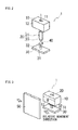
- FIG. 1A is a front view showing the configuration of a proximity sensor according to a first embodiment
- Fig. 1B is a side view thereof
- Fig. 1C is a top view thereof
- Fig. 2 is an exploded perspective view of the proximity sensor according to the first embodiment.
- a proximity sensor 1 comprises a permanent magnet (hereinafter, called a magnet) 10, a first yoke 20 held by the magnet 10, a hall IC 40 as a magnetic responsive element, and a second yoke 30.
- the magnet 10 as shown in Fig. 1B , has N pole and S pole at both ends in the right and left, and is formed in a rectangular parallelepiped having magnetic pole faces 12 and 13 each having a width W and a height H, and a length L.
- the first yoke 20 is held in a holding hole 11 of a rectangular traverse section that is formed in the center of the magnet 10 and penetrates from a top face to a bottom face thereof.
- the first yoke 20 includes a fixed primary portion 21 that is formed in a plate shape and has the same height with the height H of the magnet 10, wherein a plate face of the fixed primary portion 21 is in parallel with the magnetic pole faces 12 and 13. A top end of the fixed primary portion 21 is flush with the top face of the magnet 10, a bottom end thereof is flush with the bottom face of the magnet 10, and a projecting portion 22 projects downward from the bottom end of the fixed primary portion 21 by a predetermined amount.
- the projecting portion 22 is formed to have a quadrangle in section one side of which is equivalent to the plate thickness.
- the plate face of the fixed primary portion 21 is in parallel with the magnetic pole faces 12 and 13.
- the magnet 10 is a bond magnet produced from rare-earth magnet powder by injection-molding, and the fixed primary portion 21 in the first yoke 20 is insert-molded at the injection-molding.
- the aforementioned holding hole 11 is a conceptual hole surrounding the fixed primary portion 21 to make contact with a peripheral face thereof.
- the magnet 10 can be magnetized after being assembled by holding at least the first yoke 20.
- the second yoke 30 has a main body portion 31 that is formed in a plate shape thinner than the height H of the magnet 10, and has the same length and width as the length L and the width W of the magnet 10.
- a round bar-shaped protruding portion 32 having the same diameter as the projecting portion 22 of the first yoke 20 projects upwards by a predetermined amount from the center of the wall face of the main body portion 31 opposing the magnet 10, and opposes the projecting portion 22 to have a gap in between.
- the protruding portion 32 may have a cross section formed in a quadrangle one side of which is equivalent to the plate thickness in the same way with the projecting portion 22.
- the protruding portion 32 is formed in a round bar shape for easy production. Further, the hall IC 40 is arranged in the gap between the projecting portion 22 in the first yoke 20 and the protruding portion 32 in the second yoke 30. In the hall IC 40, the magnetic responsive direction is set in a direction of connecting the projecting portion 22 and the protruding portion 32.
- the proximity sensor 1 configured as described above is, as shown in Fig. 3 , arranged to the detected member 50 moving relative to the magnet 10 along the width W direction thereof such that the magnet 10 and the second yoke 30 are installed to oppose a moving face of the detected member 50 in such a manner that one of the magnetic pole faces in the magnet 10, for example, the magnetic pole face 12 of N pole is substantially in parallel with the plate face of the detected member 50.
- outline arrows having a white space inside thereof indicate the relative moving direction.
- the detected member 50 may be formed of, for example, a plate made of a general iron material.
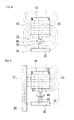
- Fig. 4 shows a magnetic circuit formed in a case where the detected member 50 is sufficiently away from the front side of the magnetic pole face 12 in the magnet 10, wherein the flowing direction of the magnetic flux shown in a broken line is indicated by an arrow.
- the magnetic flux that goes out from N pole (magnetic pole face 12) returns back to S pole (magnetic pole face 13) while drawing a loop passing through a space.
- the magnetic flux traversing the hall IC 40 is vertical to the magnetic responsive direction, the magnetic flux density is zero in a viewpoint of sensing capabilities, and the hall IC 40 is seemingly positioned in a non-magnetic field, therefore outputting an off (high) signal.
- a magnetic circuit shown in Fig. 5 is formed.
- the detected member 50 comes to a position of opposing the magnetic pole face 12 of the magnet 10 and an end face of the second yoke 30.
- the magnetic fluxes, which flow toward a side where the second yoke 30 is arranged pass through the detected member 50 via N pole, and thereafter flow into the main body portion 31 of the second yoke 30. Then a large part of the magnetic fluxes in the main body portion 31 flows in a direction of the first yoke 20 through the hall IC 40.
- the slight remaining portion of the magnetic fluxes that enter into the main body portion 31 of the second yoke 30 go directly through the space and return back to S pole in the same way with a case where the detected member 50 is sufficiently away from the front side of the magnetic pole face 12 in the magnet 10.
- the magnetic flux that flows from the second yoke 30 to the first yoke 20 via the hall IC 40 is throttled toward the projecting portion 22 having a small section, and is further throttled in the protruding portion 32 in a side of the second yoke 30. Therefore the magnetic flux concentrating on the small area passes through the hall IC 40 in a high density. Since the passing direction of the magnetic flux is along the magnetic responsive direction of the hall IC 40, the hall IC 40 detects a change in the magnetic flux density in high sensitivity and outputs an on (low) signal.
- the magnetic flux that flows from the main body portion 31 of the second yoke 30 through the space and returns back to S pole increases when the detected member 50 comes sufficiently close to the magnetic pole face 12, and the magnetic flux density applied to the hall IC 40 from the protruding portion 32 in the second yoke 30 toward the projecting portion 22 in the first yoke 20 is made small.
- the length L of the magnet 10 is controlled to be equal to or less than a value of the width W or the height H thereof.
- the plate width of the fixed primary portion 21 in parallel with the magnetic pole faces 12 and 13 is made to 20% to 40% of the width W of the magnet 10
- a large changing amount in the magnetic flux density between a case where the detected member 50 is away from the magnetic pole face 12 of the magnet 10 and a case where the detected member 50 is sufficiently close to the magnetic pole face 12 of the magnet 10 can be obtained.
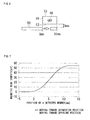
- a hall probe for a gauss meter is arranged instead of the hall IC 40, and as shown in Fig. 6 , an opposing gap between the detected member 50 and the magnetic pole face 12 is set to 3mm. A changing amount in the magnetic flux density was measured when the detected member 50 was moved between the separation position from and the opposing position to the magnet 10 (and the second yoke 30).
- a position where a front end edge of the detected member 50 in the moving direction opposes an end of the magnet 10 in the width direction was set as 0mm, wherein a changing amount in the magnetic flux density was measured in a range from a position (-5mm) before the position (0mm) of the front end edge of the detected member 50 to a position where the front end edge of the detected member 50 arrives at the other end of the magnet 10 in the width direction.
- Setting values of the proximity sensor 1 used for measurement are as follows.
- the maximum changing amount of the magnetic flux density was 55mT.
- the operation magnetic flux density of the hall IC 40 that is easy to obtain is set to 10mT, an on state and an off state of the hall IC 40 is switched in a position where the front end of the detected member 50 enters into the opposing section to the magnet 10 substantially by 2.5mm.
- the maximum changing amount of the magnetic flux density is a sufficient changing amount for the hall IC 40 having the operation magnetic flux density of 10mT, indicating that the proximity sensor 1 has a high practical use as a vehicular pedal sensor and the other sensor.
- the plate face of the fixed primary portion 21 in the first yoke 20 is arranged in parallel with the magnetic pole faces 12 and 13.
- the present embodiment has an advantage that the magnetic flux density in the hall IC 40 increases by 10% in a case where the detected member is positioned to be close to the magnetic pole face as compared to a case where the plate face of the fixed primary portion 21 is positioned to be vertical to the magnetic pole face.
- the other measurement condition was the same as the above example.
- Fig. 9 shows the measurement result.
- the magnetic flux density curve (b) in a case where the iron plate 60 was attached thereto was offset in the reduction direction by 12mT. Therefore, when the hall IC 40 having the operation magnetic flux density of 10mT is used, an on state and an off state of the hall IC 40 is switched in a position where the front end of the detected member 50 enters into the opposing section to the magnet 10 by 4.5mm. As a result, in the present example, the magnetic flux density curve can be offset by attaching the iron plate 60 to the magnetic pole face 13, thus adjusting the detection position of the detected member 50.
- the offset amount can be controlled by selection of the plate face size or the plate thickness of the iron plate 60.
- the other magnetic material may be adopted instead of the iron plate 60. Therefore when the process of the detection position adjustment is provided in the manufacturing process, a yield ratio of the proximity sensor remarkably increases, and the product requirement differing in a detection position specification of the detected member can be realized without making a change in the basic configuration and the components in the proximity sensor.
- the hall IC 40 corresponds to a magnetic responsive element in the present invention
- the iron plate 60 corresponds to a detection position adjustment plate in the present invention.
- the proximity sensor 1 in the present embodiment is configured as described above, and comprises the single magnet 10, the first yoke 20 that is held in the intermediate position between the two magnetic pole faces 12 and 13 of the magnet 10 and includes the projecting portion 22 projecting from the wall face of the magnet 10 vertical to the magnetic pole face, the second yoke 30 that includes the main body portion 31 in parallel with the wall face of the magnet 10 from which the projecting portion 22 projects and the protruding portion 32 opposing the projecting portion 22, and is arranged to have a space to the projecting portion 22, and the hall IC 40 that is arranged in the space between the projecting portion 22 and the protruding portion 32, wherein the magnet 10 is arranged to position the magnetic pole face 12 to be in parallel with the detected member 50 moving relative thereto.
- the proximity sensor can be formed of a simple structure comprising a fewer components by adopting the single magnet, and therefore can realize the detection with high accuracy by thus solving the problem of the variation in characteristics of the magnet that is unavoidable at the time of requiring a plurality of magnets.
- the magnetic flux flows in the hall IC 40 in the magnetic responsive direction from the second yoke 30 to the first yoke 20 to be throttled intensively in the projecting portion 22 and in the protruding portion 32. Therefore the change in the magnetic flux density is detected in a high sensitivity.
- the length L between the magnetic pole faces 12 and 13 of the magnet 10 is equal to or less than the width W or the height H of the magnetic pole faces 12 and 13, the changing amount of the magnetic flux density that is detected by the hall IC 40 between a case where the detected member 50 is away from the magnetic pole face 12 of the magnet 10 and a case where the detected member 50 is sufficiently close to the magnetic pole face 12 of the magnet 10 can be largely obtained.
- the projecting portion 22 extends from the plate-shaped, fixed primary portion 21 arranged in the outer shape of the magnet 10, and the plate width of the fixed primary portion 21 is larger in size than the projecting portion 22. Therefore the holding force by the magnet 10 is large, and the large changing amount of the magnetic flux density can be obtained between a case where the detected member 50 is away from the magnetic pole face 12 of the magnet 10 and a case where the detected member 50 is sufficiently close to the magnetic pole face 12 of the magnet 10.
- the magnet 10 is the bond magnet that is injection-molded from the rare-earth magnet powder, and at the time of the injection-molding, the fixed primary portion 21 of the first yoke 20 is embedded in the magnet 10 by the insert-molding to rigidly connect the first yoke 20 to the magnet 10. Therefore the variation in the characteristic of the magnet 10 due to the assembly is extremely small.
- the magnet 10 is magnetized in an assembling state of holding at least the first yoke 20, as compared to a case of assembling the first yoke 20 after the magnet 10 is magnetized, the excessive management for preventing attachment of, for example, foreign objects (magnetic powder effecting an adverse influence on the characteristic of the magnet 10 or the like) floating in the manufacturing line to the magnet 10 can be alleviated.
- the magnetic material such as the iron plate 60 is attached to the magnetic pole face 13 at the opposite side to the magnetic pole face 12 opposing the detected member 50 of the magnet 10, thereby making it possible to easily and finely adjust the detection position of the detected member 50.
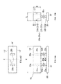
- FIG. 10A is a front view showing the configuration of a proximity sensor according to a second embodiment
- Fig. 10B is a side view thereof
- Fig. 10C is a top view thereof
- Fig. 11 is an exploded perspective view of the proximity sensor according to the second embodiment.
- a proximity sensor 1A in the second embodiment comprises a permanent magnet 10', two first yokes 20a and 20b held by the magnet 10', two hall IC 40a and 40b, and a second yoke 30'.
- the magnet 10', in Fig. 10B has N pole and S pole at both ends in the right and left, and is formed in a rectangular parallelepiped having magnetic pole faces 12' and 13' each having a width W and a height H, and a length L.
- the width (W) dimension is longer than the magnet in the first embodiment.
- Holding holes 11' each having a rectangular traverse section are provided at both sides of the magnet 10' having the center line X in the width of the magnet 10' in between to penetrate from a top face to a bottom face in an intermediate position between the magnetic pole faces 12' and 13', and each of the first yokes 20a and 20b having a cross section aligning with the holding hole 11' is held in the holding hole 11'.
- the first yoke 20a has the same shape as that of the first yoke 20b.
- Each of fixed primary portions 21a and 21b in the first yokes 20a and 20b is formed in a plate shape to have the same height as the height H of the magnet 10', and each of projecting portions 22a and 22b projects downwards from the bottom end of each by a predetermined amount.
- a top end of each of the fixed primary portions 21a and 21b is flush with the top face of the magnet 10', a bottom end thereof is flush with the bottom face of the magnet 10', and each of projecting portions 22a and 22b is formed to have a quadrangle in section one side of which is equivalent to the plate thickness.
- the plate faces of the fixed primary portions 21a and 21b are vertical to the magnetic pole faces 12' and 13' such that two detection positions to be described later can be set to any broad/narrow size.
- the magnet 10' is a rare-earth bond magnet produced by injection-molding, and each of the fixed primary portions 21a and 21b in the first yokes 20a and 20b is insert-molded at the injection-molding.
- the second yoke 30' has a main body portion 31' that is formed in a plate shape thinner than the height H of the magnet 10', has the same length and width as the length L and the width W of the magnet 10', and opposes the wall face of the magnet 10' from which the projecting portions 22a and 22b project.
- round bar-shaped protruding portions 32a and 32b project by a predetermined amount from the wall face of the main body portion 31' to oppose the projecting portions 22a and 22b of the first yokes 20a and 20b.
- Each diameter of the protruding portions 32a and 32b is equivalent to that of each of the projecting portions 22a and 22b and opposes each of the projecting portions 22a and 22b to have a gap in between.
- the hall IC 40a and 40b respectively are arranged in the gap between each of the projecting portions 22a and 22b in the first yokes 20a and 20b and each of the protruding portions 32a and 32b in the second yoke 30'.
- the magnetic responsive direction is set in a direction of connecting the projecting portion 22a and the protruding portion 32a, and in the hall IC 40b also, the magnetic responsive direction is set in a direction of connecting the projecting portion 22b and the protruding portion 32b.
- the other components are the same as those in the first embodiment.
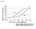
- the proximity sensor 1A is, as shown in Fig. 12 , configured such that the magnet 10' and the second yoke 30' are installed to oppose a moving face of the detected member 50' of the iron plate moving relative to the magnet 10' along the width W direction thereof in such a manner that one magnetic pole face 12' in the magnet 10' is substantially in parallel with the plate face of the detected member 50'.
- an opposing gap between the detected member 50' and the magnetic pole face 12' is set to 3mm.
- a changing amount in the magnetic flux density was measured when the detected member 50' was moved in a range from a position before an end of the magnet 10' (and the second yoke 30') in the width direction to the opposing position thereto.
- the measurement result is shown in Fig. 13 .
- a position where a front end edge of the detected member 50' in the moving direction opposes the end of the magnet 10' in the width direction is set to 0mm.
- Setting values of the proximity sensor 1 used for measurement are as follows.
- the maximum changing amount of the magnetic flux density in the gap between the projecting portion 22a and the protruding portion 32a was 51mT
- the maximum changing amount of the magnetic flux density in the gap between the projecting portion 22b and the protruding portion 32b was 49mT.
- an on state and an off state of the hall IC 40a is switched in a position where the front end of the detected member 50' enters into the opposing section to the magnet 10' by 5mm
- an on state and an off state of the hall IC 40b is switched in a position where the front end of the detected member 50' enters into the opposing section to the magnet 10' by 12mm.
- the position of the detected member 50' can be detected in two steps, and as needed, by further adding a set of the projecting portion of the first yoke , the protruding portion of the second yoke and the hall IC arranged in the gap therebetween, the position detection of the detected member can be performed in a multi-step.
- the magnetic flux density curve can be offset to adjust the detection position of the detected member 50'.
- the hall ICs 40a and 40b correspond to magnetic responsive elements in the present invention.
- the proximity magnet 1A in the present embodiment is configured as described above, and comprises the single permanent magnet 10' , the first yokes 20a and 20b that are held in an intermediate position between the two magnetic pole faces 12' and 13' of the permanent magnet 10' and include the projecting portions 22a and 22b respectively projecting from the wall face vertical to the magnetic pole faces 12' and 13', the second yoke 30' that includes the main body portion 31' in parallel with the wall face of the permanent magnet 10' from which the projecting portions 22a and 22b project and is arranged to have a space to the projecting portions 22a and 22b, and the hall ICs 40a and 40b that are arranged respectively in the spaces between the projecting portions 22a and 22b and the second yoke 30', wherein the magnet 10' is arranged to position the magnetic pole face 12' to be in parallel with the detected member 50' moving relative thereto.
- the proximity sensor can be formed of a simple structure comprising a fewer components by adopting the single magnet, and therefore can realize the detection with high accuracy by solving the problem of the variation in characteristics of the magnet that is unavoidable at the time of requiring a plurality of magnets.
- the present embodiment has the same effect as that of the first embodiment.
- the present embodiment is provided with two sets of magnetic flux density detection components composed of a first set of the first yoke 20a and the hall IC 40a arranged in the space between the projecting portion 22a and the second yoke 30', and a second set of the first yoke 20b and the hall IC 40b arranged in the space between the projecting portion 22b and the second yoke 30'. Therefore the present embodiment can realize a particular effect that the position of the detected member 50' can be detected in two steps with the single proximity sensor having a simple structure in which the number of the magnet is restricted to only one.
- the first or second embodiment and the measurement result thereof are shown based upon the example in which the detected member 50 or 50' moves in a parallel direction relative to the magnetic pole faces 12 or 12' of the magnet, but the present invention is not limited thereto. Also when the present invention is applied to a case where the detected member 50 or 50' moves in a vertical direction relative to the magnetic pole face 12 or 12' , the position of the detected member can be detected with high accuracy without being subject to the influence of the variation in the characteristic of the magnet.
- the double detection can be performed to improve the reliability.
- the magnets 10 and 10' are formed of the rare-earth bond magnets, but a bond magnet using the other magnetic material may be adopted.
- the first yoke 20, 20a or 20b is integrally jointed to the magnet 10 or 10' by insert-molding the fixed primary portion 21 and the like at the time of injection-molding the magnets 10 or 10' , but in a case where the first yoke is assembled after molding the magnet, it is preferable that the fixed primary portion 21 or the like is formed to have a cross section aligned with the holding hole 11 or 11' of the magnet and the entire periphery of four faces of the fixed primary portion makes close contact with the wall face of the holding hole.
- the height dimension of the fixed primary portion 21, 21a or 21b of the first yoke is the same as the height H of the magnet 10 or 10', and the top end thereof at the opposite side to the projecting portion 22, 22a or 22b is flush with the top face of the magnet 10 or 10', but the height dimension is only required to be at least 50% or more of the height H of the magnet, and the top end is not necessary to be exposed to the top face of the magnet.
- the structure that the top end projects from the top face of the magnet 10 is not preferable since the magnetic flux density passing through a side of the hall IC 40 is made small.
- the first embodiment has an advantage that the plate face of the fixed primary portion 21 in the first yoke 20 is arranged in parallel with the magnetic pole faces 12 and 13 to obtain a relatively large magnetic flux density in a region of the hall IC 40, but as needed, as in the case of the second embodiment, the plate face of the fixed primary portion may be arranged to be vertical to the magnetic pole face.
- the reverse structure can have the same effect.
- the protruding amount of each of the projecting portions 22, 22a and 22b of the first yoke is set to 2mm as a specific example, but as long as the protruding amount is at least 1.0mm, the high magnetic flux density can be ensured in each of the hall ICs 40, 40a and 40b in a case where the detected member is positioned to be close to the magnetic pole face.
- the section size of the projecting portion is set to a diameter of 2mm in the specific example, but if it is equivalent to a diameter of 3mm or less, the high magnetic flux density can be obtained.
- the section size is smaller than a diameter equivalent to 1mm, the magnetic flux density is made large, but it is difficult for the projecting portions 22, 22a and 22b of the first yoke to accurately oppose the protruding portions 32, 32a and 32b in the second yoke respectively, and therefore, variations on assembling tend to be easily generated.
- the above-mentioned matter can be likewise applied to the projecting amount and section size of the protruding portion in the second yoke.
- the hall IC 40 or the like is used as the magnetic responsive element, but a hall element, an MR element, a GMR element, and the other element may appropriately be adopted as the magnetic responsive element.
- the hall IC 40 in the embodiment has the particular magnetic responsive direction, but also in a case of using a magnetic responsive element of all-direction responsive type, close approach/separation of the detected member can be detected based upon a magnitude of the passing magnetic flux amount.
- the present invention is particularly effective by being applied to a pedal sensor, a door opening/closing sensor, a hood opening/closing sensor, a seat positioning sensor, or a seat belt strapping sensor for a vehicle.
- the present invention is not limited to an application to a vehicle, but can be applied to various uses for detecting the position of the detected member in non-contact.
Landscapes
- Physics & Mathematics (AREA)
- General Physics & Mathematics (AREA)
- Transmission And Conversion Of Sensor Element Output (AREA)
- Measurement Of Length, Angles, Or The Like Using Electric Or Magnetic Means (AREA)
- Switches That Are Operated By Magnetic Or Electric Fields (AREA)
Applications Claiming Priority (2)
| Application Number | Priority Date | Filing Date | Title |
|---|---|---|---|
| JP2011145175A JP5535139B2 (ja) | 2011-06-30 | 2011-06-30 | 近接センサ |
| PCT/JP2012/065970 WO2013002135A1 (fr) | 2011-06-30 | 2012-06-22 | Capteur de proximité |
Publications (3)
| Publication Number | Publication Date |
|---|---|
| EP2728302A1 true EP2728302A1 (fr) | 2014-05-07 |
| EP2728302A4 EP2728302A4 (fr) | 2015-01-14 |
| EP2728302B1 EP2728302B1 (fr) | 2018-10-17 |
Family
ID=47424031
Family Applications (1)
| Application Number | Title | Priority Date | Filing Date |
|---|---|---|---|
| EP12805389.9A Not-in-force EP2728302B1 (fr) | 2011-06-30 | 2012-06-22 | Capteur de proximité |
Country Status (5)
| Country | Link |
|---|---|
| US (1) | US9733058B2 (fr) |
| EP (1) | EP2728302B1 (fr) |
| JP (1) | JP5535139B2 (fr) |
| CN (1) | CN103827624B (fr) |
| WO (1) | WO2013002135A1 (fr) |
Cited By (3)
| Publication number | Priority date | Publication date | Assignee | Title |
|---|---|---|---|---|
| WO2014170124A1 (fr) * | 2013-04-19 | 2014-10-23 | Trw Automotive Electronics & Components Gmbh | Capteur de proximité d'un module |
| WO2017099866A1 (fr) | 2015-12-10 | 2017-06-15 | Bourns, Inc. | Capteur de proximité magnétique à longue distance |
| CN113406704A (zh) * | 2021-05-21 | 2021-09-17 | 东科克诺尔商用车制动技术有限公司 | 一种零件漏装检测装置及方法 |
Families Citing this family (11)
| Publication number | Priority date | Publication date | Assignee | Title |
|---|---|---|---|---|
| US10312395B2 (en) | 2014-09-25 | 2019-06-04 | Eni S.P.A. | Luminescent solar concentrator comprising disubstituted benzoheterodiazole compounds |
| JP6632333B2 (ja) * | 2015-11-03 | 2020-01-22 | 株式会社ヴァレオジャパン | 回転角度検出装置およびこれに用いる角度センサユニット |
| JP6561914B2 (ja) * | 2016-05-20 | 2019-08-21 | 株式会社デンソー | 位置センサ |
| EP3312564B1 (fr) * | 2016-10-20 | 2020-04-01 | Valeo Japan Co., Ltd. | Dispositif de détection d'angle de rotation et détecteur d'angle utilisé en son sein |
| JP6968545B2 (ja) * | 2017-02-01 | 2021-11-17 | オムロン株式会社 | 近接センサ |
| JP2019158569A (ja) * | 2018-03-13 | 2019-09-19 | 日本電産トーソク株式会社 | センサユニット |
| JP2019158570A (ja) * | 2018-03-13 | 2019-09-19 | 日本電産トーソク株式会社 | センサユニット |
| US11747329B2 (en) * | 2019-11-22 | 2023-09-05 | Western Digital Technologies, Inc. | Magnetic gradient concentrator/reluctance detector for molecule detection |
| JP2020177024A (ja) * | 2020-06-30 | 2020-10-29 | Tdk株式会社 | 磁場検出装置 |
| WO2022039386A1 (fr) * | 2020-08-20 | 2022-02-24 | 엘지이노텍 주식회사 | Dispositif de détection |
| JP7763567B2 (ja) * | 2022-02-10 | 2025-11-04 | 新明和工業株式会社 | 荷受台昇降装置 |
Family Cites Families (47)
| Publication number | Priority date | Publication date | Assignee | Title |
|---|---|---|---|---|
| JPS57189010A (en) * | 1981-05-15 | 1982-11-20 | Fuji Heavy Ind Ltd | Position detecting mechanism |
| JPS6028453A (ja) * | 1983-07-27 | 1985-02-13 | Mitsubishi Chem Ind Ltd | スチリル系感熱転写記録用色素及び感熱転写シート |
| US4745363A (en) | 1986-07-16 | 1988-05-17 | North American Philips Corporation | Non-oriented direct coupled gear tooth sensor using a Hall cell |
| DE3638622A1 (de) * | 1986-11-12 | 1988-05-26 | Mannesmann Kienzle Gmbh | Magnetfeldgeber |
| JPH0248934A (ja) | 1988-05-24 | 1990-02-19 | Tadao Nagase | 積層体 |
| US4970463A (en) * | 1989-03-13 | 1990-11-13 | Durakool Incorporated | Temperature stable proximity sensor with sensing of flux emanating from the lateral surface of a magnet |
| DE69024508T2 (de) * | 1989-06-13 | 1996-06-13 | Toshiba Kawasaki Kk | Elektromagnetisches Betätigungsgerät und optische Platte |
| JPH0421964A (ja) | 1990-05-17 | 1992-01-24 | Canon Inc | カセット装着装置 |
| JP2536852Y2 (ja) * | 1990-06-13 | 1997-05-28 | 株式会社 ゼクセル | 回転センサ |
| JP2964713B2 (ja) * | 1991-07-24 | 1999-10-18 | 松下電器産業株式会社 | 磁気式位置検出装置 |
| JPH07101648B2 (ja) * | 1992-04-21 | 1995-11-01 | 愛知製鋼株式会社 | 樹脂磁石組立品 |
| EP0578172A1 (fr) * | 1992-07-09 | 1994-01-12 | Siemens Aktiengesellschaft | Microrupteur avec un capteur de champ magnétique |
| JPH087232A (ja) * | 1994-06-23 | 1996-01-12 | Murata Mfg Co Ltd | 磁気センサ装置 |
| JPH08304011A (ja) * | 1995-05-15 | 1996-11-22 | Mikuni Corp | 磁気式角度センサ |
| US5781005A (en) * | 1995-06-07 | 1998-07-14 | Allegro Microsystems, Inc. | Hall-effect ferromagnetic-article-proximity sensor |
| JP3493592B2 (ja) * | 1996-02-20 | 2004-02-03 | Necトーキン株式会社 | ペイジャー用振動アクチュエータ |
| JPH09311008A (ja) * | 1996-05-23 | 1997-12-02 | Omron Corp | 磁気センサ |
| JP3984681B2 (ja) * | 1997-04-23 | 2007-10-03 | Tdk株式会社 | ボンド磁石、磁石部品およびその製造方法 |
| JP3678886B2 (ja) * | 1997-06-04 | 2005-08-03 | カルソニックカンセイ株式会社 | 位置検出装置 |
| DE19736454B4 (de) * | 1997-08-21 | 2005-01-27 | Infineon Technologies Ag | Kontaktloser Näherungsschalter |
| JPH11211410A (ja) * | 1998-01-30 | 1999-08-06 | Matsushita Electric Ind Co Ltd | 非接触型位置センサ |
| JP2001215236A (ja) * | 2000-02-03 | 2001-08-10 | Tdk Corp | 磁気回転センサ |
| JP4734766B2 (ja) * | 2000-07-18 | 2011-07-27 | Smc株式会社 | 磁石可動型電磁アクチュエータ |
| JP2003065705A (ja) * | 2001-08-27 | 2003-03-05 | Nippon Soken Inc | 変位量センサ |
| US6653830B2 (en) * | 2001-12-14 | 2003-11-25 | Wabash Technologies, Inc. | Magnetic position sensor having shaped pole pieces to provide a magnetic field having a varying magnetic flux density field strength |
| JP4066716B2 (ja) * | 2002-05-28 | 2008-03-26 | アイシン精機株式会社 | 位置検出センサ |
| JP4066723B2 (ja) * | 2002-06-19 | 2008-03-26 | アイシン精機株式会社 | 位置検出センサ |
| JP2004159984A (ja) * | 2002-11-14 | 2004-06-10 | Ge Medical Systems Global Technology Co Llc | 静磁場形成装置および磁気共鳴撮像装置 |
| JP2004177337A (ja) * | 2002-11-28 | 2004-06-24 | Aisin Seiki Co Ltd | 位置検出センサ |
| JP4198537B2 (ja) * | 2003-06-10 | 2008-12-17 | 東京マグネット応用製品株式会社 | マグネットキャッチ |
| US6809619B1 (en) * | 2003-10-16 | 2004-10-26 | G.E. Medical Systems Global Technology Co., Llc | System and method for adjusting magnetic center field for permanent MRI magnetic field generator |
| JP4557134B2 (ja) * | 2004-03-12 | 2010-10-06 | ヤマハ株式会社 | 磁気センサの製造方法、同磁気センサの製造方法に使用されるマグネットアレイ及び同マグネットアレイの製造方法 |
| JP4376726B2 (ja) * | 2004-08-06 | 2009-12-02 | Necトーキン株式会社 | 近接センサ機構 |
| EP1860670B1 (fr) * | 2005-03-17 | 2011-10-05 | Minebea Co. Ltd. | Dispositif d´aimantation à aimant permanent et procédé d´aimantation par aimant permanent |
| US7679252B2 (en) * | 2005-04-13 | 2010-03-16 | Aisin Seiki Kabushiki Kaisha | Magnet embedded motor, rotor unit, and method for manufacturing rotor unit |
| JP4792844B2 (ja) * | 2005-07-11 | 2011-10-12 | ソニー株式会社 | 像ぶれ補正装置、レンズ装置及び撮像装置 |
| JP2007085743A (ja) * | 2005-09-20 | 2007-04-05 | Tokyo Cosmos Electric Co Ltd | 非接触回転変位センサ |
| JP4607049B2 (ja) * | 2006-02-23 | 2011-01-05 | 株式会社デンソー | 回転角検出装置 |
| JP2007292511A (ja) * | 2006-04-21 | 2007-11-08 | Jtekt Corp | 位置検出装置及び電動パワーステアリング用モータ |
| CH702223B1 (de) * | 2006-06-01 | 2011-05-31 | Elesta Relays Gmbh | Set mit einem Positionssensor und einem Erregerteil. |
| JP2008021524A (ja) * | 2006-07-12 | 2008-01-31 | Tokai Rika Co Ltd | 非接触スイッチ |
| JP4435128B2 (ja) * | 2006-09-06 | 2010-03-17 | 本田技研工業株式会社 | 位置検出装置 |
| JP4891863B2 (ja) * | 2007-08-10 | 2012-03-07 | 東京コスモス電機株式会社 | 位置センサ |
| JP4397407B2 (ja) * | 2007-08-22 | 2010-01-13 | 本田技研工業株式会社 | 近接センサ |
| JP4609516B2 (ja) * | 2007-10-03 | 2011-01-12 | 株式会社デンソー | 変位検出装置 |
| JP5252724B2 (ja) * | 2009-04-16 | 2013-07-31 | 矢崎総業株式会社 | 回転角センサ |
| EP2348612A1 (fr) * | 2010-01-20 | 2011-07-27 | Siemens Aktiengesellschaft | Pièce de composant magnétique pour ensemble de rotor |
-
2011
- 2011-06-30 JP JP2011145175A patent/JP5535139B2/ja active Active
-
2012
- 2012-06-22 CN CN201280032609.6A patent/CN103827624B/zh not_active Expired - Fee Related
- 2012-06-22 WO PCT/JP2012/065970 patent/WO2013002135A1/fr not_active Ceased
- 2012-06-22 US US14/129,724 patent/US9733058B2/en not_active Expired - Fee Related
- 2012-06-22 EP EP12805389.9A patent/EP2728302B1/fr not_active Not-in-force
Cited By (5)
| Publication number | Priority date | Publication date | Assignee | Title |
|---|---|---|---|---|
| WO2014170124A1 (fr) * | 2013-04-19 | 2014-10-23 | Trw Automotive Electronics & Components Gmbh | Capteur de proximité d'un module |
| US10234588B2 (en) | 2013-04-19 | 2019-03-19 | Trw Automotive Electronics & Components Gmbh | Magnetic proximity sensor |
| WO2017099866A1 (fr) | 2015-12-10 | 2017-06-15 | Bourns, Inc. | Capteur de proximité magnétique à longue distance |
| EP3387455A4 (fr) * | 2015-12-10 | 2019-08-14 | Bourns, Inc. | Capteur de proximité magnétique à longue distance |
| CN113406704A (zh) * | 2021-05-21 | 2021-09-17 | 东科克诺尔商用车制动技术有限公司 | 一种零件漏装检测装置及方法 |
Also Published As
| Publication number | Publication date |
|---|---|
| WO2013002135A1 (fr) | 2013-01-03 |
| EP2728302A4 (fr) | 2015-01-14 |
| US20140225595A1 (en) | 2014-08-14 |
| JP2013011541A (ja) | 2013-01-17 |
| CN103827624A (zh) | 2014-05-28 |
| CN103827624B (zh) | 2016-11-16 |
| EP2728302B1 (fr) | 2018-10-17 |
| US9733058B2 (en) | 2017-08-15 |
| JP5535139B2 (ja) | 2014-07-02 |
Similar Documents
| Publication | Publication Date | Title |
|---|---|---|
| EP2728302B1 (fr) | Capteur de proximité | |
| US8836317B2 (en) | Current sensor | |
| JP6276283B2 (ja) | 磁気通貨検証ヘッド | |
| US10060759B2 (en) | Rotational angle detecting device and angle sensor unit used therein | |
| US11378771B2 (en) | Optical element driving mechanism | |
| EP2339362A1 (fr) | Module de capteur magnétique et détecteur de position de piston | |
| US8319589B2 (en) | Position sensor for mechanically latching solenoid | |
| US9018942B2 (en) | Position measurement using a variable flux collector | |
| US20070120556A1 (en) | Magnetic position sensor for a mobile object with limited linear travel | |
| JP4066716B2 (ja) | 位置検出センサ | |
| JP2004020491A (ja) | 位置検出センサ | |
| EP2972067B1 (fr) | Mesure de position en utilisant des collecteurs disposés de manière angulaire | |
| KR102490294B1 (ko) | 시트 벨트 센서의 움직임 검출 | |
| JP5675009B2 (ja) | 位置検出装置 | |
| US9347550B2 (en) | Shift lever device using magnetism detection switch | |
| WO2014045559A1 (fr) | Capteur de courant | |
| US11181394B2 (en) | Distance measuring device | |
| JP2014062831A (ja) | 磁気検出装置 | |
| US20060028308A1 (en) | Precision non-contact digital switch | |
| JPH09292202A (ja) | 直線変位検出装置 | |
| JP4342802B2 (ja) | 磁気センサ及び無接点スイッチ | |
| JP3233129B2 (ja) | 磁気検出装置 | |
| EP3312564B1 (fr) | Dispositif de détection d'angle de rotation et détecteur d'angle utilisé en son sein | |
| JP4677828B2 (ja) | 磁石装置の磁気特性調整方法 | |
| JP4055561B2 (ja) | 位置検出装置 |
Legal Events
| Date | Code | Title | Description |
|---|---|---|---|
| PUAI | Public reference made under article 153(3) epc to a published international application that has entered the european phase |
Free format text: ORIGINAL CODE: 0009012 |
|
| 17P | Request for examination filed |
Effective date: 20140108 |
|
| AK | Designated contracting states |
Kind code of ref document: A1 Designated state(s): AL AT BE BG CH CY CZ DE DK EE ES FI FR GB GR HR HU IE IS IT LI LT LU LV MC MK MT NL NO PL PT RO RS SE SI SK SM TR |
|
| DAX | Request for extension of the european patent (deleted) | ||
| A4 | Supplementary search report drawn up and despatched |
Effective date: 20141216 |
|
| RIC1 | Information provided on ipc code assigned before grant |
Ipc: G01D 5/14 20060101ALI20141208BHEP Ipc: G01V 3/08 20060101ALI20141208BHEP Ipc: G01B 7/00 20060101AFI20141208BHEP Ipc: H03K 17/95 20060101ALI20141208BHEP |
|
| GRAP | Despatch of communication of intention to grant a patent |
Free format text: ORIGINAL CODE: EPIDOSNIGR1 |
|
| STAA | Information on the status of an ep patent application or granted ep patent |
Free format text: STATUS: GRANT OF PATENT IS INTENDED |
|
| INTG | Intention to grant announced |
Effective date: 20180424 |
|
| RIN1 | Information on inventor provided before grant (corrected) |
Inventor name: SATO, SHUNICHI |
|
| GRAS | Grant fee paid |
Free format text: ORIGINAL CODE: EPIDOSNIGR3 |
|
| GRAA | (expected) grant |
Free format text: ORIGINAL CODE: 0009210 |
|
| STAA | Information on the status of an ep patent application or granted ep patent |
Free format text: STATUS: THE PATENT HAS BEEN GRANTED |
|
| AK | Designated contracting states |
Kind code of ref document: B1 Designated state(s): AL AT BE BG CH CY CZ DE DK EE ES FI FR GB GR HR HU IE IS IT LI LT LU LV MC MK MT NL NO PL PT RO RS SE SI SK SM TR |
|
| REG | Reference to a national code |
Ref country code: GB Ref legal event code: FG4D |
|
| REG | Reference to a national code |
Ref country code: CH Ref legal event code: EP |
|
| REG | Reference to a national code |
Ref country code: IE Ref legal event code: FG4D |
|
| REG | Reference to a national code |
Ref country code: DE Ref legal event code: R096 Ref document number: 602012052383 Country of ref document: DE Ref country code: AT Ref legal event code: REF Ref document number: 1054585 Country of ref document: AT Kind code of ref document: T Effective date: 20181115 |
|
| REG | Reference to a national code |
Ref country code: NL Ref legal event code: MP Effective date: 20181017 |
|
| REG | Reference to a national code |
Ref country code: LT Ref legal event code: MG4D |
|
| REG | Reference to a national code |
Ref country code: AT Ref legal event code: MK05 Ref document number: 1054585 Country of ref document: AT Kind code of ref document: T Effective date: 20181017 |
|
| PG25 | Lapsed in a contracting state [announced via postgrant information from national office to epo] |
Ref country code: NL Free format text: LAPSE BECAUSE OF FAILURE TO SUBMIT A TRANSLATION OF THE DESCRIPTION OR TO PAY THE FEE WITHIN THE PRESCRIBED TIME-LIMIT Effective date: 20181017 |
|
| PG25 | Lapsed in a contracting state [announced via postgrant information from national office to epo] |
Ref country code: BG Free format text: LAPSE BECAUSE OF FAILURE TO SUBMIT A TRANSLATION OF THE DESCRIPTION OR TO PAY THE FEE WITHIN THE PRESCRIBED TIME-LIMIT Effective date: 20190117 Ref country code: LT Free format text: LAPSE BECAUSE OF FAILURE TO SUBMIT A TRANSLATION OF THE DESCRIPTION OR TO PAY THE FEE WITHIN THE PRESCRIBED TIME-LIMIT Effective date: 20181017 Ref country code: FI Free format text: LAPSE BECAUSE OF FAILURE TO SUBMIT A TRANSLATION OF THE DESCRIPTION OR TO PAY THE FEE WITHIN THE PRESCRIBED TIME-LIMIT Effective date: 20181017 Ref country code: IS Free format text: LAPSE BECAUSE OF FAILURE TO SUBMIT A TRANSLATION OF THE DESCRIPTION OR TO PAY THE FEE WITHIN THE PRESCRIBED TIME-LIMIT Effective date: 20190217 Ref country code: NO Free format text: LAPSE BECAUSE OF FAILURE TO SUBMIT A TRANSLATION OF THE DESCRIPTION OR TO PAY THE FEE WITHIN THE PRESCRIBED TIME-LIMIT Effective date: 20190117 Ref country code: HR Free format text: LAPSE BECAUSE OF FAILURE TO SUBMIT A TRANSLATION OF THE DESCRIPTION OR TO PAY THE FEE WITHIN THE PRESCRIBED TIME-LIMIT Effective date: 20181017 Ref country code: PL Free format text: LAPSE BECAUSE OF FAILURE TO SUBMIT A TRANSLATION OF THE DESCRIPTION OR TO PAY THE FEE WITHIN THE PRESCRIBED TIME-LIMIT Effective date: 20181017 Ref country code: ES Free format text: LAPSE BECAUSE OF FAILURE TO SUBMIT A TRANSLATION OF THE DESCRIPTION OR TO PAY THE FEE WITHIN THE PRESCRIBED TIME-LIMIT Effective date: 20181017 Ref country code: LV Free format text: LAPSE BECAUSE OF FAILURE TO SUBMIT A TRANSLATION OF THE DESCRIPTION OR TO PAY THE FEE WITHIN THE PRESCRIBED TIME-LIMIT Effective date: 20181017 Ref country code: AT Free format text: LAPSE BECAUSE OF FAILURE TO SUBMIT A TRANSLATION OF THE DESCRIPTION OR TO PAY THE FEE WITHIN THE PRESCRIBED TIME-LIMIT Effective date: 20181017 |
|
| PG25 | Lapsed in a contracting state [announced via postgrant information from national office to epo] |
Ref country code: PT Free format text: LAPSE BECAUSE OF FAILURE TO SUBMIT A TRANSLATION OF THE DESCRIPTION OR TO PAY THE FEE WITHIN THE PRESCRIBED TIME-LIMIT Effective date: 20190217 Ref country code: GR Free format text: LAPSE BECAUSE OF FAILURE TO SUBMIT A TRANSLATION OF THE DESCRIPTION OR TO PAY THE FEE WITHIN THE PRESCRIBED TIME-LIMIT Effective date: 20190118 Ref country code: RS Free format text: LAPSE BECAUSE OF FAILURE TO SUBMIT A TRANSLATION OF THE DESCRIPTION OR TO PAY THE FEE WITHIN THE PRESCRIBED TIME-LIMIT Effective date: 20181017 Ref country code: SE Free format text: LAPSE BECAUSE OF FAILURE TO SUBMIT A TRANSLATION OF THE DESCRIPTION OR TO PAY THE FEE WITHIN THE PRESCRIBED TIME-LIMIT Effective date: 20181017 Ref country code: AL Free format text: LAPSE BECAUSE OF FAILURE TO SUBMIT A TRANSLATION OF THE DESCRIPTION OR TO PAY THE FEE WITHIN THE PRESCRIBED TIME-LIMIT Effective date: 20181017 |
|
| REG | Reference to a national code |
Ref country code: DE Ref legal event code: R097 Ref document number: 602012052383 Country of ref document: DE |
|
| PG25 | Lapsed in a contracting state [announced via postgrant information from national office to epo] |
Ref country code: DK Free format text: LAPSE BECAUSE OF FAILURE TO SUBMIT A TRANSLATION OF THE DESCRIPTION OR TO PAY THE FEE WITHIN THE PRESCRIBED TIME-LIMIT Effective date: 20181017 Ref country code: IT Free format text: LAPSE BECAUSE OF FAILURE TO SUBMIT A TRANSLATION OF THE DESCRIPTION OR TO PAY THE FEE WITHIN THE PRESCRIBED TIME-LIMIT Effective date: 20181017 Ref country code: CZ Free format text: LAPSE BECAUSE OF FAILURE TO SUBMIT A TRANSLATION OF THE DESCRIPTION OR TO PAY THE FEE WITHIN THE PRESCRIBED TIME-LIMIT Effective date: 20181017 |
|
| PLBE | No opposition filed within time limit |
Free format text: ORIGINAL CODE: 0009261 |
|
| STAA | Information on the status of an ep patent application or granted ep patent |
Free format text: STATUS: NO OPPOSITION FILED WITHIN TIME LIMIT |
|
| PG25 | Lapsed in a contracting state [announced via postgrant information from national office to epo] |
Ref country code: SK Free format text: LAPSE BECAUSE OF FAILURE TO SUBMIT A TRANSLATION OF THE DESCRIPTION OR TO PAY THE FEE WITHIN THE PRESCRIBED TIME-LIMIT Effective date: 20181017 Ref country code: RO Free format text: LAPSE BECAUSE OF FAILURE TO SUBMIT A TRANSLATION OF THE DESCRIPTION OR TO PAY THE FEE WITHIN THE PRESCRIBED TIME-LIMIT Effective date: 20181017 Ref country code: EE Free format text: LAPSE BECAUSE OF FAILURE TO SUBMIT A TRANSLATION OF THE DESCRIPTION OR TO PAY THE FEE WITHIN THE PRESCRIBED TIME-LIMIT Effective date: 20181017 Ref country code: SM Free format text: LAPSE BECAUSE OF FAILURE TO SUBMIT A TRANSLATION OF THE DESCRIPTION OR TO PAY THE FEE WITHIN THE PRESCRIBED TIME-LIMIT Effective date: 20181017 |
|
| 26N | No opposition filed |
Effective date: 20190718 |
|
| PG25 | Lapsed in a contracting state [announced via postgrant information from national office to epo] |
Ref country code: SI Free format text: LAPSE BECAUSE OF FAILURE TO SUBMIT A TRANSLATION OF THE DESCRIPTION OR TO PAY THE FEE WITHIN THE PRESCRIBED TIME-LIMIT Effective date: 20181017 |
|
| PG25 | Lapsed in a contracting state [announced via postgrant information from national office to epo] |
Ref country code: MC Free format text: LAPSE BECAUSE OF FAILURE TO SUBMIT A TRANSLATION OF THE DESCRIPTION OR TO PAY THE FEE WITHIN THE PRESCRIBED TIME-LIMIT Effective date: 20181017 |
|
| REG | Reference to a national code |
Ref country code: CH Ref legal event code: PL |
|
| GBPC | Gb: european patent ceased through non-payment of renewal fee |
Effective date: 20190622 |
|
| REG | Reference to a national code |
Ref country code: BE Ref legal event code: MM Effective date: 20190630 |
|
| PG25 | Lapsed in a contracting state [announced via postgrant information from national office to epo] |
Ref country code: TR Free format text: LAPSE BECAUSE OF FAILURE TO SUBMIT A TRANSLATION OF THE DESCRIPTION OR TO PAY THE FEE WITHIN THE PRESCRIBED TIME-LIMIT Effective date: 20181017 |
|
| PG25 | Lapsed in a contracting state [announced via postgrant information from national office to epo] |
Ref country code: IE Free format text: LAPSE BECAUSE OF NON-PAYMENT OF DUE FEES Effective date: 20190622 Ref country code: GB Free format text: LAPSE BECAUSE OF NON-PAYMENT OF DUE FEES Effective date: 20190622 |
|
| PG25 | Lapsed in a contracting state [announced via postgrant information from national office to epo] |
Ref country code: LU Free format text: LAPSE BECAUSE OF NON-PAYMENT OF DUE FEES Effective date: 20190622 Ref country code: BE Free format text: LAPSE BECAUSE OF NON-PAYMENT OF DUE FEES Effective date: 20190630 Ref country code: CH Free format text: LAPSE BECAUSE OF NON-PAYMENT OF DUE FEES Effective date: 20190630 Ref country code: LI Free format text: LAPSE BECAUSE OF NON-PAYMENT OF DUE FEES Effective date: 20190630 |
|
| PG25 | Lapsed in a contracting state [announced via postgrant information from national office to epo] |
Ref country code: FR Free format text: LAPSE BECAUSE OF NON-PAYMENT OF DUE FEES Effective date: 20190630 |
|
| PG25 | Lapsed in a contracting state [announced via postgrant information from national office to epo] |
Ref country code: CY Free format text: LAPSE BECAUSE OF FAILURE TO SUBMIT A TRANSLATION OF THE DESCRIPTION OR TO PAY THE FEE WITHIN THE PRESCRIBED TIME-LIMIT Effective date: 20181017 |
|
| PG25 | Lapsed in a contracting state [announced via postgrant information from national office to epo] |
Ref country code: MT Free format text: LAPSE BECAUSE OF FAILURE TO SUBMIT A TRANSLATION OF THE DESCRIPTION OR TO PAY THE FEE WITHIN THE PRESCRIBED TIME-LIMIT Effective date: 20181017 Ref country code: HU Free format text: LAPSE BECAUSE OF FAILURE TO SUBMIT A TRANSLATION OF THE DESCRIPTION OR TO PAY THE FEE WITHIN THE PRESCRIBED TIME-LIMIT; INVALID AB INITIO Effective date: 20120622 |
|
| PGFP | Annual fee paid to national office [announced via postgrant information from national office to epo] |
Ref country code: DE Payment date: 20210629 Year of fee payment: 10 |
|
| PG25 | Lapsed in a contracting state [announced via postgrant information from national office to epo] |
Ref country code: MK Free format text: LAPSE BECAUSE OF FAILURE TO SUBMIT A TRANSLATION OF THE DESCRIPTION OR TO PAY THE FEE WITHIN THE PRESCRIBED TIME-LIMIT Effective date: 20181017 |
|
| REG | Reference to a national code |
Ref country code: DE Ref legal event code: R119 Ref document number: 602012052383 Country of ref document: DE |
|
| PG25 | Lapsed in a contracting state [announced via postgrant information from national office to epo] |
Ref country code: DE Free format text: LAPSE BECAUSE OF NON-PAYMENT OF DUE FEES Effective date: 20230103 |