EP2728558B1 - Ablagemodul - Google Patents
Ablagemodul Download PDFInfo
- Publication number
- EP2728558B1 EP2728558B1 EP13180809.9A EP13180809A EP2728558B1 EP 2728558 B1 EP2728558 B1 EP 2728558B1 EP 13180809 A EP13180809 A EP 13180809A EP 2728558 B1 EP2728558 B1 EP 2728558B1
- Authority
- EP
- European Patent Office
- Prior art keywords
- item
- media
- orientation
- region
- deposit module
- Prior art date
- Legal status (The legal status is an assumption and is not a legal conclusion. Google has not performed a legal analysis and makes no representation as to the accuracy of the status listed.)
- Active
Links
Images




Classifications
-
- G—PHYSICS
- G07—CHECKING-DEVICES
- G07F—COIN-FREED OR LIKE APPARATUS
- G07F19/00—Complete banking systems; Coded card-freed arrangements adapted for dispensing or receiving monies or the like and posting such transactions to existing accounts, e.g. automatic teller machines
- G07F19/20—Automatic teller machines [ATMs]
- G07F19/202—Depositing operations within ATMs
-
- B—PERFORMING OPERATIONS; TRANSPORTING
- B65—CONVEYING; PACKING; STORING; HANDLING THIN OR FILAMENTARY MATERIAL
- B65H—HANDLING THIN OR FILAMENTARY MATERIAL, e.g. SHEETS, WEBS, CABLES
- B65H5/00—Feeding articles separated from piles; Feeding articles to machines
- B65H5/06—Feeding articles separated from piles; Feeding articles to machines by rollers or balls, e.g. between rollers
- B65H5/062—Feeding articles separated from piles; Feeding articles to machines by rollers or balls, e.g. between rollers between rollers or balls
-
- B—PERFORMING OPERATIONS; TRANSPORTING
- B65—CONVEYING; PACKING; STORING; HANDLING THIN OR FILAMENTARY MATERIAL
- B65H—HANDLING THIN OR FILAMENTARY MATERIAL, e.g. SHEETS, WEBS, CABLES
- B65H5/00—Feeding articles separated from piles; Feeding articles to machines
- B65H5/18—Feeding articles separated from piles; Feeding articles to machines by rotary dials or tables
-
- B—PERFORMING OPERATIONS; TRANSPORTING
- B65—CONVEYING; PACKING; STORING; HANDLING THIN OR FILAMENTARY MATERIAL
- B65H—HANDLING THIN OR FILAMENTARY MATERIAL, e.g. SHEETS, WEBS, CABLES
- B65H9/00—Registering, e.g. orientating, articles; Devices therefor
- B65H9/002—Registering, e.g. orientating, articles; Devices therefor changing orientation of sheet by only controlling movement of the forwarding means, i.e. without the use of stop or register wall
-
- G—PHYSICS
- G07—CHECKING-DEVICES
- G07D—HANDLING OF COINS OR VALUABLE PAPERS, e.g. TESTING, SORTING BY DENOMINATIONS, COUNTING, DISPENSING, CHANGING OR DEPOSITING
- G07D11/00—Devices accepting coins; Devices accepting, dispensing, sorting or counting valuable papers
- G07D11/10—Mechanical details
- G07D11/16—Handling of valuable papers
- G07D11/17—Aligning
-
- G—PHYSICS
- G07—CHECKING-DEVICES
- G07D—HANDLING OF COINS OR VALUABLE PAPERS, e.g. TESTING, SORTING BY DENOMINATIONS, COUNTING, DISPENSING, CHANGING OR DEPOSITING
- G07D11/00—Devices accepting coins; Devices accepting, dispensing, sorting or counting valuable papers
- G07D11/10—Mechanical details
- G07D11/16—Handling of valuable papers
- G07D11/18—Diverting into different paths or containers
-
- B—PERFORMING OPERATIONS; TRANSPORTING
- B65—CONVEYING; PACKING; STORING; HANDLING THIN OR FILAMENTARY MATERIAL
- B65H—HANDLING THIN OR FILAMENTARY MATERIAL, e.g. SHEETS, WEBS, CABLES
- B65H2301/00—Handling processes for sheets or webs
- B65H2301/30—Orientation, displacement, position of the handled material
- B65H2301/33—Modifying, selecting, changing orientation
- B65H2301/332—Turning, overturning
- B65H2301/3321—Turning, overturning kinetic therefor
- B65H2301/33216—Turning, overturning kinetic therefor about an axis perpendicular to the direction of displacement and to the surface of material
-
- B—PERFORMING OPERATIONS; TRANSPORTING
- B65—CONVEYING; PACKING; STORING; HANDLING THIN OR FILAMENTARY MATERIAL
- B65H—HANDLING THIN OR FILAMENTARY MATERIAL, e.g. SHEETS, WEBS, CABLES
- B65H2301/00—Handling processes for sheets or webs
- B65H2301/30—Orientation, displacement, position of the handled material
- B65H2301/33—Modifying, selecting, changing orientation
- B65H2301/332—Turning, overturning
- B65H2301/3322—Turning, overturning according to a determined angle
- B65H2301/33222—90°
-
- B—PERFORMING OPERATIONS; TRANSPORTING
- B65—CONVEYING; PACKING; STORING; HANDLING THIN OR FILAMENTARY MATERIAL
- B65H—HANDLING THIN OR FILAMENTARY MATERIAL, e.g. SHEETS, WEBS, CABLES
- B65H2403/00—Power transmission; Driving means
- B65H2403/50—Driving mechanisms
- B65H2403/51—Cam mechanisms
-
- B—PERFORMING OPERATIONS; TRANSPORTING
- B65—CONVEYING; PACKING; STORING; HANDLING THIN OR FILAMENTARY MATERIAL
- B65H—HANDLING THIN OR FILAMENTARY MATERIAL, e.g. SHEETS, WEBS, CABLES
- B65H2404/00—Parts for transporting or guiding the handled material
- B65H2404/10—Rollers
- B65H2404/14—Roller pairs
- B65H2404/144—Roller pairs with relative movement of the rollers to / from each other
- B65H2404/1442—Tripping arrangements
-
- B—PERFORMING OPERATIONS; TRANSPORTING
- B65—CONVEYING; PACKING; STORING; HANDLING THIN OR FILAMENTARY MATERIAL
- B65H—HANDLING THIN OR FILAMENTARY MATERIAL, e.g. SHEETS, WEBS, CABLES
- B65H2405/00—Parts for holding the handled material
- B65H2405/50—Gripping means
- B65H2405/53—Rotary gripping arms
Definitions
- the present invention relates to a deposit module for use in an Automated Teller Machine and a method of operating a deposit module.
- Various types of Self-Service Terminal are known in which items of media can be dispensed and/or deposited.
- an SST may be an Automated Teller Machine (ATM), kiosk, or the like.
- ATM Automated Teller Machine
- Such terminals are used to store items of media as sheet-like elements and dispense these from time to time as requested by a user.
- Certain SSTs also enable users to deposit such items of media from time to time.
- the items of media themselves which can be currency notes, cheques, giros, lottery tickets, envelopes or the like, are typically shaped in a non-symmetric fashion.
- currency notes are typically rectangular in shape having two parallel spaced apart long edges and two parallel spaced apart short edges.
- certain SSTs or certain modules within certain SSTs the items of media must be presented and processed in a specific orientation.
- cash dispensers and cash and cheque acceptors transport and store their documents in different orientations approximately 90° different to each other. This makes them and bin modules and cassettes used in such terminals/modules incompatible with each other.
- Cash dispensers conventionally move cash through their modules long edge first.
- some cash and cheque acceptors move documents short edge first. This makes for a considerable degree of incompatibility between differing terminals and modules which increases cost and reduces a user experience at the terminal since different slots having different sizes to receive or dispense items of media in different orientations must be provided in a front panel of the ATM.
- WO00/52649 A1 describes a combination bill accepting and bill dispensing device, which uses a processing junction with banknote accumulators arranged on either side thereof and a banknote vault or stacker located at one end of the processing junction; wherein, if a banknote situated in the processing junction is to be accumulated for later dispensing, it will be moved laterally to either one or the other accumulator and wherein banknotes are accumulated with their longitudinal axis aligned with the longitudinal axis of the cylinder on which they are rolled.
- US4343582 A describes a banknote dispensing apparatus.
- EP1139303 A2 describes a reversing and aligning mechanism for sheet processing apparatus.
- US6343686 B1 describes a rotating clamp for changing the orientation of a substrate stack.
- US4591046 A describes a turntable transfer mechanism for conveyors.
- US2010/090396 A1 describes a sheet conveying apparatus and a recording apparatus.
- a deposit module comprising: a first region in which a media item is transported in a first orientation; a further region in which the media item is transported in a further orientation; and a re-orientation device configured to (i) transport the media item between the first and further regions and (ii) rotate the media item between the first and further orientations; characterised in that the re-orientation device comprises: a rotatable item guide rotatable by a drive shaft; and at least one clamping element configured to selectively clamp an item of media to move with the item guide, and configured to automatically release a clamped item from the item guide, as the item guide rotates to a pre-determined location; and in that a first axis of transport associated with the first region is substantially parallel to
- the re-orientation device further comprises:
- the deposit module further comprises a solenoid configured to selectively locate said first roller in an engaged or disengaged mode of operation.
- the deposit module further comprises a further roller configured to selectively drive an item of media along said further region towards and/or away from the re-orientation device.
- the deposit module further comprises a solenoid configured to selectively locate said further roller in an engaged or disengaged mode of operation.
- the transport path is bi-directional.
- the first orientation is rotated substantially 90° with respect to the further orientation.
- SST Self-Service Terminal
- the SST may comprise an ATM.
- a method of transporting at least one item of media along a transport path in a deposit module as described above comprising the steps of:
- Also described herein is a method of transporting at least one item of media along a transport path in a deposit module, comprising the steps of: transporting an item of media along a first region or a further region of a guide surface; transporting the item of media from a one of the first or further regions to a remainder one of the first or further regions via a re-orientation device; and transporting the item of media along a remainder one region; whereby as said item of media is transported between the first and further regions, an item of media is re-orientated from an orientation associated with said a one region to an orientation associated with said remainder one region.
- Also described herein is a method of re-orientating an item of media in a deposit module, comprising the steps of: transporting an item of media, in a first orientation, to a turntable; rotating the turntable to re-orientate the item of media; and transporting the re-orientated item of media from the turntable.
- a Self-Service Terminal for transporting at least one item of media along a transport path, comprising: at least one guide surface comprising a first region in which an item of media is transported in a first orientation with respect to a respective direction of transport, and a further region in which an item of media is transported in a further orientation with respect to a respective direction of transport; and a re-orientation module that transports an item of media between the first and further regions and rotates an item of media received at a one of the first and further regions into an orientation associated with a remainder one of the first and further regions.
- SST Self-Service Terminal
- Also described herein is a method of transporting at least one item of media along a transport path in a Self-Service Terminal (SST), comprising the steps of: transporting an item of media along a first region or a further region of a guide surface; transporting the item of media from a one of the first or further regions to a remainder one of the first or further regions via a re-orientation module; and transporting the item of media along a remainder one region; whereby as said item of media is transported between the first and further regions, an item of media is re-orientated from an orientation associated with said a one region to an orientation associated with said remainder one region.
- SST Self-Service Terminal
- Also described herein is a method of re-orientating an item of media in a Self-Service Terminal (SST), comprising the steps of: transporting an item of media, in a first orientation, to a turntable; rotating the turntable to re-orientate the item of media; and transporting the re-orientated item of media from the turntable.
- SST Self-Service Terminal
- the turntable may rotate in a plane parallel to an entrance slot of the SST.
- a deposit module for transporting at least one item of media along a transport path, comprising: at least one guide surface comprising a first region in which an item of media is transported in a first orientation with respect to a respective direction of transport, and a further region in which an item of media is transported in a further orientation with respect to a respective direction of transport; and a re-orientation module that transports an item of media between the first and further regions and rotates an item of media received at a one of the first and further regions into an orientation associated with a remainder one of the first and further regions.
- Certain examples of the present description enable a transported document to be rotated through about around 90° or more, for example, from a short edge orientation to a long edge orientation within an SST or deposit module, making it possible to transport items into a first region where items must travel long edge first from a source of items which provides items in a short edge first configuration.
- Certain examples of the present description enable items to be returned from a long edge first source to a short edge first target location.
- Certain examples of the present description rotate documents being transported through about around 90°, for example, from short edge to long edge first orientations.
- Certain examples of the present description enable items of media to be automatically rotated to a desired onward orientation appropriate to a pathway which is to be followed subsequent to the orientation step.
- multiple input paths and multiple output paths can be interconnected by a common orientation device.
- the transport paths may be spaced apart radially about the re-orientation device and the items of media are rotated through an appropriate angle of rotation for onward transport.
- FIG. 1A illustrates a self-service dispense and deposit terminal in the form of an Automated Teller Machine (ATM) 100.
- ATM Automated Teller Machine
- FIG. 1A illustrates a self-service dispense and deposit terminal in the form of an Automated Teller Machine (ATM) 100.
- ATM Automated Teller Machine
- FIG. 1A illustrates a self-service dispense and deposit terminal in the form of an Automated Teller Machine (ATM) 100.
- ATM Automated Teller Machine
- the ATM 100 includes a fascia 101 coupled to a chassis (not shown).
- the fascia 101 defines an aperture 102 through which a camera (not shown) images a customer of the ATM 100.
- the fascia 101 also defines a number of slots for receiving and dispensing media items and a tray 103 into which coins can be dispensed.
- the slots include a statement output slot 104, a receipt slot 105, a card reader slot 106, a cash dispense slot 107, a cash and cheque deposit slot 108 and a branding badge 110.
- the slots and tray are arranged such that the slots and tray align with corresponding ATM modules mounted within the chassis of the ATM.
- the fascia 101 provides a user interface for allowing an ATM customer to execute a transaction.
- the fascia 101 includes an encrypting keyboard 120 for allowing an ATM customer to enter transaction details.
- a display 130 is provided for presenting screens to an ATM customer.
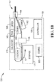
- a media item depository 150 is shown in more detail in Figure 1B .
- the deposit module 150 includes a chassis 155 onto which various parts are mounted.
- the depository 150 further includes a bunch deposit slot 108 at which a customer (not shown) can introduce a bunch 157 of currency notes or other such items of media (such as cheques). This enables the sheet items of media to be deposited by a customer.
- a bunch loader 158 co-operates with an upper loading unit 160 and a lower dispatch unit 162. These co-operate to receive the bunch of items of media and move them to a pick unit 165 or return them to a customer via slot 108 respectively.
- the pick unit 165 is aligned with the bunch loader 158 for removing individual sheets from the bunch of sheets 157.
- a sheet validator 170 determines whether the items of media are valid.
- An escrow 175 is provided for temporarily storing validated sheets until a customer confirms they wish to complete a transaction.
- a storage compartment 177 is provided as well as a communication circuit board 180 for communicating with the self-service terminal 100 into which the depository 150 may be installed.
- An on-board controller 185 is provided for controlling the operation of the depository 150.
- the depository 150 includes a plurality of transport units only some of which are described herein.
- An upper sheet transport section 160 is located above the bunch loader 158 and adjacent to the picker 165.
- a lower sheet transport section 162 is located beneath the bunch loader 158 and near the bunch deposit slot 108.
- the bunch loader 158 is used to transport deposited currency notes from the bunch deposit slot 108 to the pick unit 165.
- a first route is shown by arrow A and involves the sheet media item being picked from the bunch of sheets 157, transported to the picker unit 165, moved past the validator 170 to be identified and validated, placed in the escrow 175 and from the escrow 175 transported into the storage compartment 177.
- the second optional route is shown by the arrow B and involves the sheet item being picked from the bunch of sheets 157, transported to the picker unit 165, moved past the validator 170 to be identified and validated, placed in the escrow 175 and from the escrow 175 returned to the customer via a rebunching unit 190 and via the loading unit 158 and lower transport section 162.
- a sheet item is stored (that is to say, follows the route shown by arrow A) or returned to a customer (that is to say, follows a path shown by arrow B) depends on a number of factors, such as whether the sheet is recognised, whether a sheet is validated and/or whether a customer cancels or confirms a transaction or the like.
- Figure 2 illustrates a guide surface 200 along which items of media are transported in the deposit module 150.
- a re-orientation device 210 in the form of a turntable is located in an intermediate region 215 of the guide surface.
- To the left hand side (in Figure 2 ) of the guide surface 200 is a first region 220 of the guide surface.
- To the right hand side of Figure 2 is a further region 225 of the guide surface 200.
- the first region 220, intermediate region 215 and further region 225 of the guide surface 200 define a bi-directional transport path between the left and right hand sides of the guide surface 200. It will be understood that uni-directional transport of items of media can be envisaged according to certain other embodiments of the present invention.
- the turntable 210 and guide surface 200 may be used in any module of an SST.
- certain embodiments of the present invention may be utilised in deposit modules and/or dispense modules and/or recycle modules.
- Certain embodiments of the present invention can thus be utilised to change an orientation of a document/item being processed wherever desired. This may be used to increase storage capacity of certain modules. For example, when documents are deposited in a short edge orientation there may be room for only two stacks of items in the depth of a storage container. By contrast, if those items can be rotated 90° then there may be room for four or more stacks.
- the guide surface 200 provides a support surface that supports and guides items of media as they are transported. Rollers are driven to rotate to move the items of media on the guide surface.
- the rollers may be arranged in pairs as per the pairs of rollers 230 0 , 230 1 shown in Figure 2 or as single rollers 235.
- an arrangement of parallel spaced apart driven endless belts 240 can also be utilised to move items of media along on the guide surface 200.
- a clamping point 250 which also operates as a release point depending upon a direction of transport, is provided when the turntable is at one position of rotation. The turntable rotates in a selective controlled manner, as will be described hereinafter in more detail, to locate items of media between this clamping position and a further clamping position (not shown in Figure 2 ) where the items of media can again be released or picked up.
- Figure 2 also helps illustrate a position of a deskew drive roller 255 which is driven selectively and used to align a currency note being transported in the left to right direction subsequent to re-orientation by the turntable-like mechanism.
- Items input at a first end 255 of the lower guide surface 200 ride along on an upstanding edge 260 of the guide which helps keep the item correctly aligned.
- Items leaving the lower guide at a further end 265 ride along an upstanding edge 270 which helps align the item.
- Figure 3 helps illustrate an upper guide surface 300 which is opposed to and spaced apart from the lower guide surface 200 shown in Figure 2 .
- Figure 3 helps illustrate how a drive solenoid 310 is connected to pairs of idlers 320 via a connecting pin network.
- the idlers 320 With the drive solenoid 310 driven into an engaged mode of operation, the idlers 320 are extended downwardly from a lower surface of the upper guide towards the driven rollers which extend through the lower guide surface.
- the solenoid 310 driven into a disengaged mode of operation the idlers 320 are withdrawn from the guide surface and thus the driven rollers below.
- Figure 3 also helps illustrate the movement of items of media in a left-to-right mode of operation.
- items of media are introduced at a first end 330 of the guide surface 300 in a direction of transport illustrated by arrow A.
- the driven rollers 230 0 and opposed idle rollers move the item of media, such as a currency note, from left to right with an edge of a currency note being located against an abutment surface 260 of the lower guide surface 200 and moved past a circuit board 340 adjacent to the upper guide surface 300.
- the items of media eventually reach the turntable 210 which acts as a re-orientation module and which picks up the items of media and rotates them through the intermediate region 215 into a further region 225 of the transport pathway.
- a further solenoid 350 is used to engage or disengage another set of idlers 360 from the drive rollers 230 1 , 235 in the lower guide surface.
- a deskew solenoid 370 is activated to release a deskew idler 380. With the deskew solenoid 370 activated the roller comes into contact with an item of media as it is released from the re-orientation module. The document is caught between the deskew drive roller and an idler which results in the document being moved towards the track base edge. The document is thus forced to align with the track base. Subsequent to deskewing the deskew drive roller is disengaged. The document is thereafter transported by the rollers/idlers and flat belts, long edge first. Items of media are then transported away from the turntable 210 along a direction of transport illustrated by arrow B by drive belts 240 in the lower guide surface and opposed guide belts 385 in the upper guide surface to a further end 390 of the guide surface 300.
- Figure 4 illustrates motion of an item of media 400 in various positions along a transport path in the direction of transport illustrated in Figure 3 .
- the first position of the currency note 400 shown in Figure 4 is the position 410 illustrated to the left of the turntable 210.
- the currency note 400 moves in a respective direction of transport A with an edge of the currency note 400 abutting the abutment surface 260 which helps locate the currency note as it is transported.
- the currency note is moved by virtue of the opposed driven rollers 230 and idlers until it reaches the clamping position 250.
- a clamping mechanism on the turntable closes to releasably secure the item of media to a rotating element of the turntable.
- the turntable is then rotated in a counter-clockwise direction about a central axis of rotation.
- a second position 420 in which the turntable has begun to turn from the clamping/release position 250 carrying a currency note with it, is illustrated in Figure 4 .
- the rotating parts of the turntable-like mechanism 210 continue to turn in a counter-clockwise fashion until the item of media/currency note 400 reaches a further position 430 illustrated in Figure 4 .
- the turntable element operates in such a way so as to release the item of media.
- An edge of the currency note 400 thereafter becomes aligned with a further abutment surface 270 in the further region 225 of the transport pathway by operation of the deskew motor and roller.
- the currency note 400 has been re-orientated from a short edge first orientation shown at the first position 410 to a long edge first orientation shown in a fourth position 440 shown in Figure 4 with respect to a particular direction of transport. Thereafter, the currency note 400 is driven by the drive rollers and drive belts along a respective direction of transport B. It will be appreciated that the direction of transport illustrated by arrow A and arrow B are substantially parallel but spaced apart. For bi-directional transport a further deskew motor and roller can optionally be included to urge a currency note against the abutment surface 320.
- FIG. 5 illustrates two different orientations of a currency note 400.
- Each currency note has a first short edge 500 and a further short edge 505. The short edges are substantially parallel and spaced apart.
- Each currency note 400 also includes a first long edge 510 and a further long edge 515. Each long edge is substantially parallel and spaced apart from the other.
- Each currency note 400 is thus substantially rectangular in shape.
- a longitudinal axis of the currency note is substantially perpendicular to a direction of transport B. This is described as a long edge first orientation 520.
- a longitudinal axis of the currency note is substantially parallel with a direction of transport. This is described as a short edge first orientation. Items of media having other shapes and thus different possible orientations with respect to a direction of transport can of course be utilised according to certain other embodiments of the present invention.
- Figure 6 illustrates how motion of currency notes on the guide surface 200 are monitored and how the arrival of a currency note at a pre-determined position may be detected.
- An array of sensors 600 0...8 are illustrated in Figure 6 .
- Each array is utilised to monitor when a leading edge of a currency note reaches a pre-determined position 610 with respect to that sensor array.
- each sensor array can be a reflectance or transmittance sensor. When a signal from a respective sensor array 600 changes state, this indicates that a leading edge of a currency note has reached a particular position on the guide surface 200. This is utilised to control driving of rollers, the turntable 210 and/or the drive belts 240. It will be appreciated that other detection mechanisms can be utilised and could, for example, be utilised to detect a trailing edge of a currency note providing that a shape and size of the item of media being transported is pre-known or previously determined.
- the document is thus transported short edge first, left to right in Figure 6 (or right to left if bi-directional transport is envisaged) with a bottom edge aligned to an abutment surface on the base.
- the leading and trailing edge of the document is recorded by sensors for document tracking and timing component actuation within the module. For example, when an item of media lead edge passes the sensor 600 2 the document can be slowed down until its lead edge reaches the pre-determined identification location 610 detected by the sensors 600 3 . At this point, the item of media is within the turntable mechanism.
- Identifying the presence of the item of media at this location triggers a speeding up in rotational speed of the turntable (which is otherwise stationary until the continually running transport system delivers a next item of media at the pre-determined location 610) to help match the item velocity to the turntable speed. Slowing the transport velocity prior to clamping a currency note helps avoid misalignment and jams.
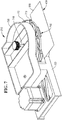
- Figure 7 illustrates a currency note 400 presented at a clamping position 250 corresponding to a leading edge 500 being detected at the identification position 610 on the guide surface.
- the re-orientation module 210 includes an upper housing 700, an upper rotating guide 710, a lower rotating guide 720 and a base 730.
- the base 730 and upper housing 700 are fixed in position rigidly with respect to the guide surface 200.
- the rotating upper and lower guides 710, 720 are rotated by a drive shaft 740.
- One of three clamps 750 carried by the rotating upper and lower guide is utilised to clamp the currency note 400 to move with the rotating upper and lower guides so that the currency note 400 moves with the guides as they are rotated.
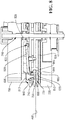
- FIG. 8 illustrates the clamping action in more detail.
- Each clamp 750 includes a clamping foot 800 which is secured to a plunger 810 and clamp arm 820.
- the foot 800, plunger 810 and arm 820 may be separate elements or may be integrally formed.
- the clamp arm 820 is pivotably secured about a pivot point 825 to a top surface 830 of the upper guide 710. The clamp is thus able to pivot up and down in a vertical direction about the pivot point 825.
- a top surface 835 of the plunger 810 is a convex abutment surface which rides on a downward facing cam surface 840 of the upper housing 700.
- the cam surface 840 which can be seen more clearly in Figure 9 , has a profile which extends downwardly with respect to a lower surface of the upper housing at one or more regions where items of media are to be clamped to the rotating elements of the re-orientation module 210.
- the currency notes 400 are secured by being squeezed between a lower surface 845 of the foot 800 of the clamp and a bumper 850 which is secured at a respective position to the lower guide 720.
- a ball bearing retainer 855 which is a generally circular plate holding a multitude of ball bearings 860 in a substantially ring-like configuration helps ensure easy rotation of the various rotating elements of the re-orientation module 210.
- the ball bearings run in an upper race 870 on a lower surface of the lower guide 720 and a lower race 880 in an upper surface of the base 730.
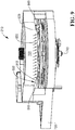
- Figure 9 illustrates a further view of the re-orientation module 210 and, in particular, helps illustrate how the cam surface 840 which is utilised to press down on the plunger 810 of each clamp arm 820 is provided by the body of the upper housing 700.
- Each clamp arm 820 is spring biased against the upper cam surface 840.
- the cam surface 840 of the upper housing 700 is generally circular but from a recessed region 900 the cam surface 840 generally extends downwardly in an intermediate region 910 into a lower running region 920.
- the housing is fixed in place with respect to the guide surface 200 but as the drive shaft 740 is rotated the upper and lower guide plates 710, 720 carrying the clamps rotate with respect to the cam surface 840.
- the upper abutment surfaces of the plungers of each clamp ride on the cam surface 840 as the guide plates carrying the plungers rotate. In the recessed regions the clamps are biased away from opposed bumpers 880 carried on the lower guide.
- an abutment surface rides on the cam surface 840 and begins to move downwardly in the intermediate region 910 of the cam surface 840.
- the steadily downwardly inclined and smooth cam surface 840 thus generally presses the plunger downwardly thereby clamping any item of media between the plunger and an opposed bumper.
- the continued rotation of the upper and lower guides by driving the drive shaft 740 continues to rotate the upper and lower guides.
- a further intermediate region 930 of the cam surface 840 provides a transitional region in which a clamp plunger begins to lift away from an item of media. This releases the item of media.
- the cam surface 840 in the housing then reaches the recessed region 900 which extends in a circular shape so that the abutment surfaces of plungers can continually ride on the cam surface 840 ready for the next downward transition.
- the guide plates are decelerated and stopped once an item of media has been suitably released until the next item of media arrives.
- FIG 10 illustrates an exploded view of the re-orientation module 210 in more detail.
- the base 730 is a substantially rigid body having, at a first end 1000 thereof, a circular lower bearing race 880.
- a further end region 1010 of the base 730 is used to house a motor 855 and other parts of the re-orientation module 210.
- the ball bearing retainer which retains a ring of ball bearings 860 sits on the lower race 880 and the ball bearings 860 in the retainer 855 locate with an upper race 870 in a lower surface of the lower guide 720.
- Three clamps 820 are illustrated in Figure 10 although the number of clamps can of course be selected according to need.
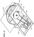
- Figure 11 illustrates an underside of the re-orientation housing and illustrates how a stepper motor 1100 is used to drive a motor drive shaft 1110. This in turn drives a drive belt 1120 which is used to drive the drive shaft 740.
- a sensor plate 1130 is secured to a bottom end of the drive shaft 740.
- the sensor plate 1130 has three notches 1140 cut into it. Other detectable elements rather than notches could of course be utilised to mark a particular position.
- the motor 1100 is a stepper motor and starts to rotate when an item of media arrives at a set point such as the identification position 610 when a next cycle is to begin. A partial revolution is then carried out to rotate the plunger of the clamp, which is clamping an item of media to the turntable-like mechanism, so that it rides over the length of the downwardly extending cam surface.
- a deposit module Such a module may optionally be incorporated in an SST such as an ATM.
- SST such as an ATM.
- the words “comprise” and “contain” and variations of them mean “including but not limited to” and they are not intended to (and do not) exclude other moieties, additives, components, integers or steps.
- the singular encompasses the plural unless the context otherwise requires.
- the specification is to be understood as contemplating plurality as well as singularity, unless the context requires otherwise.
Landscapes
- Physics & Mathematics (AREA)
- General Physics & Mathematics (AREA)
- Engineering & Computer Science (AREA)
- Mechanical Engineering (AREA)
- Business, Economics & Management (AREA)
- Accounting & Taxation (AREA)
- Finance (AREA)
- Registering Or Overturning Sheets (AREA)
- Separation, Sorting, Adjustment, Or Bending Of Sheets To Be Conveyed (AREA)
- Discharge By Other Means (AREA)
- Feeding Of Articles By Means Other Than Belts Or Rollers (AREA)
Claims (11)
- Verwahrungsmodul (150), umfassend:eine erste Region (220), in der ein Medienelement (400) in einer ersten Ausrichtung transportiert wird;eine weitere Region (225), in der das Medienelement (400) in einer weiteren Ausrichtung transportiert wird; und
eine Neuorientierungsvorrichtung (210), die konfiguriert ist zum: (i) Transportieren des Medienelements (400) zwischen der ersten (220) und weiteren (225) Regionen und (ii) Drehen des Medienelements (400) zwischen der ersten und weiteren Ausrichtungen;wobei die Neuausrichtungsvorrichtung (210) umfasst:eine drehbare Elementführung (720), die durch eine Antriebswelle (740) drehbar ist; undmindestens eine Klemmverbindung (750), die konfiguriert ist, ein Medienelement (400) selektiv zu klemmen, sodass es sich mit der Elementführung (720) bewegt, und konfiguriert ist, ein geklemmtes Element (400) von der Elementführung (720) automatisch freizugeben, während sich die Elementführung (720) zu einem vorbestimmten Ort dreht;und dadurch, dass eine erste Transportachse, die mit der ersten Region (220) verbunden ist, im Wesentlichen parallel zu einer weiteren Transportachse ist und davon beabstandet ist, die mit der weiteren Region (225) verbunden ist;und dadurch, dass das Verwahrungsmodul angepasst ist, in einen Geldautomaten (100) integriert zu werden und jedes Medienelement (400) eine Banknote oder ein Scheck ist. - Verwahrungsmodul nach Anspruch 1, wobei die Neuorientierungsvorrichtung (210) ferner umfasst:ein Gehäuse (700), das eine Nockenlauffläche (840) umfasst; wobeidas Klemmelement (750) eine Anlagefläche (835) umfasst, die konfiguriert ist, in die Nockenlauffläche (840) einzugreifen, um ein Medienelement (400) an vorbestimmten Orten selektiv zu klemmen oder freizugeben, während sich das Klemmelement (750) in Bezug auf die Nockenlauffläche (840) dreht.
- Verwahrungsmodul nach Anspruch 1 oder Anspruch 2, wobei die Neuorientierungsvorrichtung (210) ferner umfasst:eine Basis (730), die einen unteren Lagerlaufring (880) umfasst;eine Halterung (885), die mehrere Rollen (860) umfasst; undeinen oberen Lagerlaufring (870) auf einer unteren Fläche der Elementführung (720).
- Verwahrungsmodul nach einem vorstehenden Anspruch, ferner umfassend:einen Antriebsriemen (1120), der die Antriebswelle (740) mit einem Motor (1100) verbindet;eine Einstellscheibe (1130), die auf der Antriebswelle (740) angebracht ist und mindestens eine Markierung (1140) umfasst; undmindestens einen Sensor (1150), der einen Ort von jeder Markierung (1140) bestimmt.
- Verwahrungsmodul nach einem vorstehenden Anspruch, ferner umfassend:
eine erste Rolle (320), die konfiguriert ist, ein Medienelement (400) entlang der ersten Region (220) in Richtung der Neuorientierungsvorrichtung (210) und/oder davon weg selektiv anzusteuern. - Verwahrungsmodul nach Anspruch 5, ferner umfassend:
ein Magnetventil (310), das konfiguriert ist, die erste Rolle (320) in einem Eingriffs- oder Ausgerücktbetriebsmodus selektiv anzuordnen. - Verwahrungsmodul nach einem vorstehenden Anspruch, ferner umfassend:
eine weitere Rolle (360), die konfiguriert ist, ein Medienelement (400) entlang der weiteren Region (225) in Richtung der Neuorientierungsvorrichtung (210) und/oder davon weg selektiv anzusteuern. - Verwahrungsmodul nach Anspruch 7, ferner umfassend:
ein Magnetventil (350), das konfiguriert ist, die weitere Rolle (360) in einem Eingriffs- oder Ausgerücktbetriebsmodus selektiv anzuordnen. - Verwahrungsmodul nach einem vorstehenden Anspruch, wobei der Transportweg bidirektional ist.
- Verwahrungsmodul nach einem vorstehenden Anspruch, wobei die erste Ausrichtung in Bezug auf die weitere Ausrichtung im Wesentlichen um 90 ° gedreht ist.
- Verfahren zum Transportieren von mindestens einem Medienelement (400) entlang einem Transportweg in einem Verwahrungsmodul (150) nach einem der vorstehenden Ansprüche, wobei das Verfahren die Schritte aufweist:Transportieren eines Medienelements (400) entlang einer ersten Region (220) oder einer weiteren Region (225) einer Führungsfläche (200);Neuausrichten des Medienelements (400); undTransportieren des Medienelements (400) zu der anderen der ersten oder weiteren Regionen (220, 225); wobei das Medienelement eine Banknote oder ein Scheck ist.
Applications Claiming Priority (1)
| Application Number | Priority Date | Filing Date | Title |
|---|---|---|---|
| US13/663,947 US8973917B2 (en) | 2012-10-30 | 2012-10-30 | Deposit module |
Publications (2)
| Publication Number | Publication Date |
|---|---|
| EP2728558A1 EP2728558A1 (de) | 2014-05-07 |
| EP2728558B1 true EP2728558B1 (de) | 2019-10-30 |
Family
ID=49033824
Family Applications (1)
| Application Number | Title | Priority Date | Filing Date |
|---|---|---|---|
| EP13180809.9A Active EP2728558B1 (de) | 2012-10-30 | 2013-08-19 | Ablagemodul |
Country Status (4)
| Country | Link |
|---|---|
| US (1) | US8973917B2 (de) |
| EP (1) | EP2728558B1 (de) |
| CN (1) | CN103787156B (de) |
| BR (1) | BR102013025146B1 (de) |
Families Citing this family (2)
| Publication number | Priority date | Publication date | Assignee | Title |
|---|---|---|---|---|
| US11276267B2 (en) | 2019-08-30 | 2022-03-15 | Ncr Corporation | Media rotation mechanism |
| US20250118127A1 (en) * | 2023-10-05 | 2025-04-10 | Igt Global Solutions Corporation | Lottery ticket vending machine |
Citations (4)
| Publication number | Priority date | Publication date | Assignee | Title |
|---|---|---|---|---|
| US4591046A (en) * | 1983-04-04 | 1986-05-27 | R. R. Donnelley & Sons Company | Turntable transfer mechanism for conveyors |
| US4979730A (en) * | 1989-11-14 | 1990-12-25 | Pitney Bowes Inc. | Sheet drive system having an encoder apparatus |
| US6343686B1 (en) * | 2000-05-09 | 2002-02-05 | Xerox Corporation | Rotating clamp for changing the orientation of a substrate stack |
| US20100090395A1 (en) * | 2008-10-10 | 2010-04-15 | Lasermax Roll Systems, Inc. | System and method for rotating sheets |
Family Cites Families (5)
| Publication number | Priority date | Publication date | Assignee | Title |
|---|---|---|---|---|
| SE411803B (sv) | 1977-10-11 | 1980-02-04 | Lundblad Leif | Anordning for utmatning av blad fran ett forrad av blad, exempelvis sedlar, till en for sassorer eller kunder tillgenglig uttagsoppning |
| CA2327771C (en) | 1999-03-03 | 2007-07-10 | Cashcode Company Inc. | Combination bill accepting and bill dispensing device |
| EP1139303B1 (de) | 2000-03-23 | 2014-11-12 | Kabushiki Kaisha Toshiba | Umkehrungs- und Ausrichtungsmechanismus für Blattgutverarbeitungsvorrichtung |
| EP1321403A1 (de) * | 2001-12-20 | 2003-06-25 | Mars Incorporated | Verfahren und Vorrichtung zur Ausrichtung einer Banknote |
| US8262076B2 (en) * | 2010-07-08 | 2012-09-11 | Ncr Corporation | Media depository |
-
2012
- 2012-10-30 US US13/663,947 patent/US8973917B2/en active Active
-
2013
- 2013-08-19 EP EP13180809.9A patent/EP2728558B1/de active Active
- 2013-09-30 BR BR102013025146-1A patent/BR102013025146B1/pt active IP Right Grant
- 2013-10-29 CN CN201310535733.0A patent/CN103787156B/zh active Active
Patent Citations (4)
| Publication number | Priority date | Publication date | Assignee | Title |
|---|---|---|---|---|
| US4591046A (en) * | 1983-04-04 | 1986-05-27 | R. R. Donnelley & Sons Company | Turntable transfer mechanism for conveyors |
| US4979730A (en) * | 1989-11-14 | 1990-12-25 | Pitney Bowes Inc. | Sheet drive system having an encoder apparatus |
| US6343686B1 (en) * | 2000-05-09 | 2002-02-05 | Xerox Corporation | Rotating clamp for changing the orientation of a substrate stack |
| US20100090395A1 (en) * | 2008-10-10 | 2010-04-15 | Lasermax Roll Systems, Inc. | System and method for rotating sheets |
Also Published As
| Publication number | Publication date |
|---|---|
| US20140117614A1 (en) | 2014-05-01 |
| EP2728558A1 (de) | 2014-05-07 |
| CN103787156A (zh) | 2014-05-14 |
| US8973917B2 (en) | 2015-03-10 |
| BR102013025146B1 (pt) | 2021-07-13 |
| CN103787156B (zh) | 2016-05-18 |
| BR102013025146A2 (pt) | 2014-11-25 |
Similar Documents
| Publication | Publication Date | Title |
|---|---|---|
| CN100337889C (zh) | 薄片接收装置和回收装置 | |
| JP5169612B2 (ja) | 紙葉類処理装置 | |
| CN104050751B (zh) | 纸张类处理装置 | |
| EP2469483B1 (de) | Medienausgabegerät | |
| TWI466067B (zh) | Banknote handling device | |
| US8961275B2 (en) | Coin depositing and dispensing machine | |
| CN104837753B (zh) | 取入送出装置、介质收纳库和介质处理装置 | |
| EP2728558B1 (de) | Ablagemodul | |
| EP3567560B1 (de) | Wertbriefkassette | |
| JP2011141612A (ja) | 紙葉類取扱装置 | |
| US8899475B2 (en) | Media presenter | |
| EP2600321B1 (de) | Artikelstapelung | |
| JP5791464B2 (ja) | 紙幣保留分離機構とこれを用いた還流式紙幣処理装置 | |
| JP2013238945A (ja) | 紙葉類取扱装置及び自動取引装置 | |
| JP5010168B2 (ja) | 硬貨搬送装置 | |
| KR101609455B1 (ko) | 매체 보관함 및 금융기기 | |
| KR20160149778A (ko) | 매체 이송 장치 | |
| JP2011054058A (ja) | 紙葉類収納庫 | |
| KR101153639B1 (ko) | 매체처리장치 및 방법과 금융기기 | |
| JP5101153B2 (ja) | 紙幣払い出し装置 | |
| JP6022371B2 (ja) | 発券装置および券売機 | |
| JP2007302452A (ja) | 紙葉類処理装置 | |
| JP2007018147A (ja) | 紙幣集積装置及び取引処理装置 | |
| JPH0243167A (ja) | 紙葉束の搬送装置 | |
| JPH1131247A (ja) | 紙葉類分離給送装置 |
Legal Events
| Date | Code | Title | Description |
|---|---|---|---|
| PUAI | Public reference made under article 153(3) epc to a published international application that has entered the european phase |
Free format text: ORIGINAL CODE: 0009012 |
|
| 17P | Request for examination filed |
Effective date: 20130819 |
|
| AK | Designated contracting states |
Kind code of ref document: A1 Designated state(s): AL AT BE BG CH CY CZ DE DK EE ES FI FR GB GR HR HU IE IS IT LI LT LU LV MC MK MT NL NO PL PT RO RS SE SI SK SM TR |
|
| AX | Request for extension of the european patent |
Extension state: BA ME |
|
| 17P | Request for examination filed |
Effective date: 20141107 |
|
| RBV | Designated contracting states (corrected) |
Designated state(s): AL AT BE BG CH CY CZ DE DK EE ES FI FR GB GR HR HU IE IS IT LI LT LU LV MC MK MT NL NO PL PT RO RS SE SI SK SM TR |
|
| RAP1 | Party data changed (applicant data changed or rights of an application transferred) |
Owner name: NCR CORPORATION |
|
| STAA | Information on the status of an ep patent application or granted ep patent |
Free format text: STATUS: EXAMINATION IS IN PROGRESS |
|
| 17Q | First examination report despatched |
Effective date: 20190115 |
|
| GRAP | Despatch of communication of intention to grant a patent |
Free format text: ORIGINAL CODE: EPIDOSNIGR1 |
|
| STAA | Information on the status of an ep patent application or granted ep patent |
Free format text: STATUS: GRANT OF PATENT IS INTENDED |
|
| INTG | Intention to grant announced |
Effective date: 20190717 |
|
| GRAS | Grant fee paid |
Free format text: ORIGINAL CODE: EPIDOSNIGR3 |
|
| GRAA | (expected) grant |
Free format text: ORIGINAL CODE: 0009210 |
|
| STAA | Information on the status of an ep patent application or granted ep patent |
Free format text: STATUS: THE PATENT HAS BEEN GRANTED |
|
| AK | Designated contracting states |
Kind code of ref document: B1 Designated state(s): AL AT BE BG CH CY CZ DE DK EE ES FI FR GB GR HR HU IE IS IT LI LT LU LV MC MK MT NL NO PL PT RO RS SE SI SK SM TR |
|
| REG | Reference to a national code |
Ref country code: GB Ref legal event code: FG4D |
|
| REG | Reference to a national code |
Ref country code: CH Ref legal event code: EP |
|
| REG | Reference to a national code |
Ref country code: AT Ref legal event code: REF Ref document number: 1196977 Country of ref document: AT Kind code of ref document: T Effective date: 20191115 |
|
| REG | Reference to a national code |
Ref country code: DE Ref legal event code: R084 Ref document number: 602013062195 Country of ref document: DE |
|
| REG | Reference to a national code |
Ref country code: DE Ref legal event code: R096 Ref document number: 602013062195 Country of ref document: DE |
|
| REG | Reference to a national code |
Ref country code: IE Ref legal event code: FG4D |
|
| REG | Reference to a national code |
Ref country code: GB Ref legal event code: 746 Effective date: 20191114 |
|
| REG | Reference to a national code |
Ref country code: LT Ref legal event code: MG4D |
|
| PG25 | Lapsed in a contracting state [announced via postgrant information from national office to epo] |
Ref country code: GR Free format text: LAPSE BECAUSE OF FAILURE TO SUBMIT A TRANSLATION OF THE DESCRIPTION OR TO PAY THE FEE WITHIN THE PRESCRIBED TIME-LIMIT Effective date: 20200131 Ref country code: FI Free format text: LAPSE BECAUSE OF FAILURE TO SUBMIT A TRANSLATION OF THE DESCRIPTION OR TO PAY THE FEE WITHIN THE PRESCRIBED TIME-LIMIT Effective date: 20191030 Ref country code: NL Free format text: LAPSE BECAUSE OF FAILURE TO SUBMIT A TRANSLATION OF THE DESCRIPTION OR TO PAY THE FEE WITHIN THE PRESCRIBED TIME-LIMIT Effective date: 20191030 Ref country code: LT Free format text: LAPSE BECAUSE OF FAILURE TO SUBMIT A TRANSLATION OF THE DESCRIPTION OR TO PAY THE FEE WITHIN THE PRESCRIBED TIME-LIMIT Effective date: 20191030 Ref country code: BG Free format text: LAPSE BECAUSE OF FAILURE TO SUBMIT A TRANSLATION OF THE DESCRIPTION OR TO PAY THE FEE WITHIN THE PRESCRIBED TIME-LIMIT Effective date: 20200130 Ref country code: PT Free format text: LAPSE BECAUSE OF FAILURE TO SUBMIT A TRANSLATION OF THE DESCRIPTION OR TO PAY THE FEE WITHIN THE PRESCRIBED TIME-LIMIT Effective date: 20200302 Ref country code: ES Free format text: LAPSE BECAUSE OF FAILURE TO SUBMIT A TRANSLATION OF THE DESCRIPTION OR TO PAY THE FEE WITHIN THE PRESCRIBED TIME-LIMIT Effective date: 20191030 Ref country code: SE Free format text: LAPSE BECAUSE OF FAILURE TO SUBMIT A TRANSLATION OF THE DESCRIPTION OR TO PAY THE FEE WITHIN THE PRESCRIBED TIME-LIMIT Effective date: 20191030 Ref country code: LV Free format text: LAPSE BECAUSE OF FAILURE TO SUBMIT A TRANSLATION OF THE DESCRIPTION OR TO PAY THE FEE WITHIN THE PRESCRIBED TIME-LIMIT Effective date: 20191030 Ref country code: PL Free format text: LAPSE BECAUSE OF FAILURE TO SUBMIT A TRANSLATION OF THE DESCRIPTION OR TO PAY THE FEE WITHIN THE PRESCRIBED TIME-LIMIT Effective date: 20191030 Ref country code: NO Free format text: LAPSE BECAUSE OF FAILURE TO SUBMIT A TRANSLATION OF THE DESCRIPTION OR TO PAY THE FEE WITHIN THE PRESCRIBED TIME-LIMIT Effective date: 20200130 |
|
| REG | Reference to a national code |
Ref country code: NL Ref legal event code: MP Effective date: 20191030 |
|
| PG25 | Lapsed in a contracting state [announced via postgrant information from national office to epo] |
Ref country code: IS Free format text: LAPSE BECAUSE OF FAILURE TO SUBMIT A TRANSLATION OF THE DESCRIPTION OR TO PAY THE FEE WITHIN THE PRESCRIBED TIME-LIMIT Effective date: 20200229 Ref country code: HR Free format text: LAPSE BECAUSE OF FAILURE TO SUBMIT A TRANSLATION OF THE DESCRIPTION OR TO PAY THE FEE WITHIN THE PRESCRIBED TIME-LIMIT Effective date: 20191030 Ref country code: RS Free format text: LAPSE BECAUSE OF FAILURE TO SUBMIT A TRANSLATION OF THE DESCRIPTION OR TO PAY THE FEE WITHIN THE PRESCRIBED TIME-LIMIT Effective date: 20191030 |
|
| PG25 | Lapsed in a contracting state [announced via postgrant information from national office to epo] |
Ref country code: AL Free format text: LAPSE BECAUSE OF FAILURE TO SUBMIT A TRANSLATION OF THE DESCRIPTION OR TO PAY THE FEE WITHIN THE PRESCRIBED TIME-LIMIT Effective date: 20191030 |
|
| PG25 | Lapsed in a contracting state [announced via postgrant information from national office to epo] |
Ref country code: CZ Free format text: LAPSE BECAUSE OF FAILURE TO SUBMIT A TRANSLATION OF THE DESCRIPTION OR TO PAY THE FEE WITHIN THE PRESCRIBED TIME-LIMIT Effective date: 20191030 Ref country code: EE Free format text: LAPSE BECAUSE OF FAILURE TO SUBMIT A TRANSLATION OF THE DESCRIPTION OR TO PAY THE FEE WITHIN THE PRESCRIBED TIME-LIMIT Effective date: 20191030 Ref country code: RO Free format text: LAPSE BECAUSE OF FAILURE TO SUBMIT A TRANSLATION OF THE DESCRIPTION OR TO PAY THE FEE WITHIN THE PRESCRIBED TIME-LIMIT Effective date: 20191030 Ref country code: DK Free format text: LAPSE BECAUSE OF FAILURE TO SUBMIT A TRANSLATION OF THE DESCRIPTION OR TO PAY THE FEE WITHIN THE PRESCRIBED TIME-LIMIT Effective date: 20191030 |
|
| REG | Reference to a national code |
Ref country code: DE Ref legal event code: R097 Ref document number: 602013062195 Country of ref document: DE |
|
| REG | Reference to a national code |
Ref country code: AT Ref legal event code: MK05 Ref document number: 1196977 Country of ref document: AT Kind code of ref document: T Effective date: 20191030 |
|
| PG25 | Lapsed in a contracting state [announced via postgrant information from national office to epo] |
Ref country code: SM Free format text: LAPSE BECAUSE OF FAILURE TO SUBMIT A TRANSLATION OF THE DESCRIPTION OR TO PAY THE FEE WITHIN THE PRESCRIBED TIME-LIMIT Effective date: 20191030 Ref country code: SK Free format text: LAPSE BECAUSE OF FAILURE TO SUBMIT A TRANSLATION OF THE DESCRIPTION OR TO PAY THE FEE WITHIN THE PRESCRIBED TIME-LIMIT Effective date: 20191030 Ref country code: IT Free format text: LAPSE BECAUSE OF FAILURE TO SUBMIT A TRANSLATION OF THE DESCRIPTION OR TO PAY THE FEE WITHIN THE PRESCRIBED TIME-LIMIT Effective date: 20191030 |
|
| PLBE | No opposition filed within time limit |
Free format text: ORIGINAL CODE: 0009261 |
|
| STAA | Information on the status of an ep patent application or granted ep patent |
Free format text: STATUS: NO OPPOSITION FILED WITHIN TIME LIMIT |
|
| 26N | No opposition filed |
Effective date: 20200731 |
|
| PG25 | Lapsed in a contracting state [announced via postgrant information from national office to epo] |
Ref country code: AT Free format text: LAPSE BECAUSE OF FAILURE TO SUBMIT A TRANSLATION OF THE DESCRIPTION OR TO PAY THE FEE WITHIN THE PRESCRIBED TIME-LIMIT Effective date: 20191030 Ref country code: SI Free format text: LAPSE BECAUSE OF FAILURE TO SUBMIT A TRANSLATION OF THE DESCRIPTION OR TO PAY THE FEE WITHIN THE PRESCRIBED TIME-LIMIT Effective date: 20191030 |
|
| PG25 | Lapsed in a contracting state [announced via postgrant information from national office to epo] |
Ref country code: MC Free format text: LAPSE BECAUSE OF FAILURE TO SUBMIT A TRANSLATION OF THE DESCRIPTION OR TO PAY THE FEE WITHIN THE PRESCRIBED TIME-LIMIT Effective date: 20191030 |
|
| REG | Reference to a national code |
Ref country code: CH Ref legal event code: PL |
|
| PG25 | Lapsed in a contracting state [announced via postgrant information from national office to epo] |
Ref country code: LI Free format text: LAPSE BECAUSE OF NON-PAYMENT OF DUE FEES Effective date: 20200831 Ref country code: CH Free format text: LAPSE BECAUSE OF NON-PAYMENT OF DUE FEES Effective date: 20200831 Ref country code: LU Free format text: LAPSE BECAUSE OF NON-PAYMENT OF DUE FEES Effective date: 20200819 |
|
| REG | Reference to a national code |
Ref country code: BE Ref legal event code: MM Effective date: 20200831 |
|
| PG25 | Lapsed in a contracting state [announced via postgrant information from national office to epo] |
Ref country code: IE Free format text: LAPSE BECAUSE OF NON-PAYMENT OF DUE FEES Effective date: 20200819 Ref country code: BE Free format text: LAPSE BECAUSE OF NON-PAYMENT OF DUE FEES Effective date: 20200831 |
|
| PG25 | Lapsed in a contracting state [announced via postgrant information from national office to epo] |
Ref country code: TR Free format text: LAPSE BECAUSE OF FAILURE TO SUBMIT A TRANSLATION OF THE DESCRIPTION OR TO PAY THE FEE WITHIN THE PRESCRIBED TIME-LIMIT Effective date: 20191030 Ref country code: MT Free format text: LAPSE BECAUSE OF FAILURE TO SUBMIT A TRANSLATION OF THE DESCRIPTION OR TO PAY THE FEE WITHIN THE PRESCRIBED TIME-LIMIT Effective date: 20191030 Ref country code: CY Free format text: LAPSE BECAUSE OF FAILURE TO SUBMIT A TRANSLATION OF THE DESCRIPTION OR TO PAY THE FEE WITHIN THE PRESCRIBED TIME-LIMIT Effective date: 20191030 |
|
| PG25 | Lapsed in a contracting state [announced via postgrant information from national office to epo] |
Ref country code: MK Free format text: LAPSE BECAUSE OF FAILURE TO SUBMIT A TRANSLATION OF THE DESCRIPTION OR TO PAY THE FEE WITHIN THE PRESCRIBED TIME-LIMIT Effective date: 20191030 |
|
| P01 | Opt-out of the competence of the unified patent court (upc) registered |
Effective date: 20230506 |
|
| REG | Reference to a national code |
Ref country code: DE Ref legal event code: R081 Ref document number: 602013062195 Country of ref document: DE Owner name: CARDTRONICS USA, INC. (GESELLSCHAFT NACH DEN G, US Free format text: FORMER OWNER: NCR CORPORATION, ATLANTA, GA, US |
|
| PGFP | Annual fee paid to national office [announced via postgrant information from national office to epo] |
Ref country code: DE Payment date: 20250827 Year of fee payment: 13 |
|
| PGFP | Annual fee paid to national office [announced via postgrant information from national office to epo] |
Ref country code: GB Payment date: 20250827 Year of fee payment: 13 |
|
| PGFP | Annual fee paid to national office [announced via postgrant information from national office to epo] |
Ref country code: FR Payment date: 20250825 Year of fee payment: 13 |