EP2729202B2 - Injecteur de type stylo avec module de mesure et d'affichage de dose - Google Patents
Injecteur de type stylo avec module de mesure et d'affichage de dose Download PDFInfo
- Publication number
- EP2729202B2 EP2729202B2 EP12735504.8A EP12735504A EP2729202B2 EP 2729202 B2 EP2729202 B2 EP 2729202B2 EP 12735504 A EP12735504 A EP 12735504A EP 2729202 B2 EP2729202 B2 EP 2729202B2
- Authority
- EP
- European Patent Office
- Prior art keywords
- drug
- drug delivery
- expelling
- delivery system
- dosing
- Prior art date
- Legal status (The legal status is an assumption and is not a legal conclusion. Google has not performed a legal analysis and makes no representation as to the accuracy of the status listed.)
- Active
Links
Images




Classifications
-
- G—PHYSICS
- G16—INFORMATION AND COMMUNICATION TECHNOLOGY [ICT] SPECIALLY ADAPTED FOR SPECIFIC APPLICATION FIELDS
- G16H—HEALTHCARE INFORMATICS, i.e. INFORMATION AND COMMUNICATION TECHNOLOGY [ICT] SPECIALLY ADAPTED FOR THE HANDLING OR PROCESSING OF MEDICAL OR HEALTHCARE DATA
- G16H20/00—ICT specially adapted for therapies or health-improving plans, e.g. for handling prescriptions, for steering therapy or for monitoring patient compliance
- G16H20/10—ICT specially adapted for therapies or health-improving plans, e.g. for handling prescriptions, for steering therapy or for monitoring patient compliance relating to drugs or medications, e.g. for ensuring correct administration to patients
- G16H20/17—ICT specially adapted for therapies or health-improving plans, e.g. for handling prescriptions, for steering therapy or for monitoring patient compliance relating to drugs or medications, e.g. for ensuring correct administration to patients delivered via infusion or injection
-
- A—HUMAN NECESSITIES
- A61—MEDICAL OR VETERINARY SCIENCE; HYGIENE
- A61M—DEVICES FOR INTRODUCING MEDIA INTO, OR ONTO, THE BODY; DEVICES FOR TRANSDUCING BODY MEDIA OR FOR TAKING MEDIA FROM THE BODY; DEVICES FOR PRODUCING OR ENDING SLEEP OR STUPOR
- A61M5/00—Devices for bringing media into the body in a subcutaneous, intra-vascular or intramuscular way; Accessories therefor, e.g. filling or cleaning devices, arm-rests
- A61M5/178—Syringes
- A61M5/24—Ampoule syringes, i.e. syringes with needle for use in combination with replaceable ampoules or carpules, e.g. automatic
-
- A—HUMAN NECESSITIES
- A61—MEDICAL OR VETERINARY SCIENCE; HYGIENE
- A61M—DEVICES FOR INTRODUCING MEDIA INTO, OR ONTO, THE BODY; DEVICES FOR TRANSDUCING BODY MEDIA OR FOR TAKING MEDIA FROM THE BODY; DEVICES FOR PRODUCING OR ENDING SLEEP OR STUPOR
- A61M5/00—Devices for bringing media into the body in a subcutaneous, intra-vascular or intramuscular way; Accessories therefor, e.g. filling or cleaning devices, arm-rests
- A61M5/178—Syringes
- A61M5/31—Details
- A61M5/315—Pistons; Piston-rods; Guiding, blocking or restricting the movement of the rod or piston; Appliances on the rod for facilitating dosing ; Dosing mechanisms
- A61M5/31525—Dosing
-
- A—HUMAN NECESSITIES
- A61—MEDICAL OR VETERINARY SCIENCE; HYGIENE
- A61M—DEVICES FOR INTRODUCING MEDIA INTO, OR ONTO, THE BODY; DEVICES FOR TRANSDUCING BODY MEDIA OR FOR TAKING MEDIA FROM THE BODY; DEVICES FOR PRODUCING OR ENDING SLEEP OR STUPOR
- A61M5/00—Devices for bringing media into the body in a subcutaneous, intra-vascular or intramuscular way; Accessories therefor, e.g. filling or cleaning devices, arm-rests
- A61M5/178—Syringes
- A61M5/31—Details
- A61M5/315—Pistons; Piston-rods; Guiding, blocking or restricting the movement of the rod or piston; Appliances on the rod for facilitating dosing ; Dosing mechanisms
- A61M5/31533—Dosing mechanisms, i.e. setting a dose
- A61M5/31535—Means improving security or handling thereof, e.g. blocking means, means preventing insufficient dosing, means allowing correction of overset dose
-
- G—PHYSICS
- G16—INFORMATION AND COMMUNICATION TECHNOLOGY [ICT] SPECIALLY ADAPTED FOR SPECIFIC APPLICATION FIELDS
- G16H—HEALTHCARE INFORMATICS, i.e. INFORMATION AND COMMUNICATION TECHNOLOGY [ICT] SPECIALLY ADAPTED FOR THE HANDLING OR PROCESSING OF MEDICAL OR HEALTHCARE DATA
- G16H15/00—ICT specially adapted for medical reports, e.g. generation or transmission thereof
-
- G—PHYSICS
- G16—INFORMATION AND COMMUNICATION TECHNOLOGY [ICT] SPECIALLY ADAPTED FOR SPECIFIC APPLICATION FIELDS
- G16H—HEALTHCARE INFORMATICS, i.e. INFORMATION AND COMMUNICATION TECHNOLOGY [ICT] SPECIALLY ADAPTED FOR THE HANDLING OR PROCESSING OF MEDICAL OR HEALTHCARE DATA
- G16H40/00—ICT specially adapted for the management or administration of healthcare resources or facilities; ICT specially adapted for the management or operation of medical equipment or devices
- G16H40/60—ICT specially adapted for the management or administration of healthcare resources or facilities; ICT specially adapted for the management or operation of medical equipment or devices for the operation of medical equipment or devices
- G16H40/63—ICT specially adapted for the management or administration of healthcare resources or facilities; ICT specially adapted for the management or operation of medical equipment or devices for the operation of medical equipment or devices for local operation
-
- A—HUMAN NECESSITIES
- A61—MEDICAL OR VETERINARY SCIENCE; HYGIENE
- A61M—DEVICES FOR INTRODUCING MEDIA INTO, OR ONTO, THE BODY; DEVICES FOR TRANSDUCING BODY MEDIA OR FOR TAKING MEDIA FROM THE BODY; DEVICES FOR PRODUCING OR ENDING SLEEP OR STUPOR
- A61M5/00—Devices for bringing media into the body in a subcutaneous, intra-vascular or intramuscular way; Accessories therefor, e.g. filling or cleaning devices, arm-rests
- A61M5/178—Syringes
- A61M5/31—Details
- A61M2005/3125—Details specific display means, e.g. to indicate dose setting
- A61M2005/3126—Specific display means related to dosing
-
- A—HUMAN NECESSITIES
- A61—MEDICAL OR VETERINARY SCIENCE; HYGIENE
- A61M—DEVICES FOR INTRODUCING MEDIA INTO, OR ONTO, THE BODY; DEVICES FOR TRANSDUCING BODY MEDIA OR FOR TAKING MEDIA FROM THE BODY; DEVICES FOR PRODUCING OR ENDING SLEEP OR STUPOR
- A61M5/00—Devices for bringing media into the body in a subcutaneous, intra-vascular or intramuscular way; Accessories therefor, e.g. filling or cleaning devices, arm-rests
- A61M5/178—Syringes
- A61M5/31—Details
- A61M5/3129—Syringe barrels
- A61M2005/3142—Modular constructions, e.g. supplied in separate pieces to be assembled by end-user
-
- A—HUMAN NECESSITIES
- A61—MEDICAL OR VETERINARY SCIENCE; HYGIENE
- A61M—DEVICES FOR INTRODUCING MEDIA INTO, OR ONTO, THE BODY; DEVICES FOR TRANSDUCING BODY MEDIA OR FOR TAKING MEDIA FROM THE BODY; DEVICES FOR PRODUCING OR ENDING SLEEP OR STUPOR
- A61M2205/00—General characteristics of the apparatus
- A61M2205/33—Controlling, regulating or measuring
- A61M2205/3306—Optical measuring means
-
- A—HUMAN NECESSITIES
- A61—MEDICAL OR VETERINARY SCIENCE; HYGIENE
- A61M—DEVICES FOR INTRODUCING MEDIA INTO, OR ONTO, THE BODY; DEVICES FOR TRANSDUCING BODY MEDIA OR FOR TAKING MEDIA FROM THE BODY; DEVICES FOR PRODUCING OR ENDING SLEEP OR STUPOR
- A61M2205/00—General characteristics of the apparatus
- A61M2205/50—General characteristics of the apparatus with microprocessors or computers
-
- A—HUMAN NECESSITIES
- A61—MEDICAL OR VETERINARY SCIENCE; HYGIENE
- A61M—DEVICES FOR INTRODUCING MEDIA INTO, OR ONTO, THE BODY; DEVICES FOR TRANSDUCING BODY MEDIA OR FOR TAKING MEDIA FROM THE BODY; DEVICES FOR PRODUCING OR ENDING SLEEP OR STUPOR
- A61M2205/00—General characteristics of the apparatus
- A61M2205/50—General characteristics of the apparatus with microprocessors or computers
- A61M2205/502—User interfaces, e.g. screens or keyboards
-
- A—HUMAN NECESSITIES
- A61—MEDICAL OR VETERINARY SCIENCE; HYGIENE
- A61M—DEVICES FOR INTRODUCING MEDIA INTO, OR ONTO, THE BODY; DEVICES FOR TRANSDUCING BODY MEDIA OR FOR TAKING MEDIA FROM THE BODY; DEVICES FOR PRODUCING OR ENDING SLEEP OR STUPOR
- A61M2205/00—General characteristics of the apparatus
- A61M2205/50—General characteristics of the apparatus with microprocessors or computers
- A61M2205/52—General characteristics of the apparatus with microprocessors or computers with memories providing a history of measured variating parameters of apparatus or patient
-
- A—HUMAN NECESSITIES
- A61—MEDICAL OR VETERINARY SCIENCE; HYGIENE
- A61M—DEVICES FOR INTRODUCING MEDIA INTO, OR ONTO, THE BODY; DEVICES FOR TRANSDUCING BODY MEDIA OR FOR TAKING MEDIA FROM THE BODY; DEVICES FOR PRODUCING OR ENDING SLEEP OR STUPOR
- A61M2205/00—General characteristics of the apparatus
- A61M2205/82—Internal energy supply devices
- A61M2205/8206—Internal energy supply devices battery-operated
- A61M2205/8212—Internal energy supply devices battery-operated with means or measures taken for minimising energy consumption
-
- A—HUMAN NECESSITIES
- A61—MEDICAL OR VETERINARY SCIENCE; HYGIENE
- A61M—DEVICES FOR INTRODUCING MEDIA INTO, OR ONTO, THE BODY; DEVICES FOR TRANSDUCING BODY MEDIA OR FOR TAKING MEDIA FROM THE BODY; DEVICES FOR PRODUCING OR ENDING SLEEP OR STUPOR
- A61M2209/00—Ancillary equipment
- A61M2209/04—Tools for specific apparatus
-
- A—HUMAN NECESSITIES
- A61—MEDICAL OR VETERINARY SCIENCE; HYGIENE
- A61M—DEVICES FOR INTRODUCING MEDIA INTO, OR ONTO, THE BODY; DEVICES FOR TRANSDUCING BODY MEDIA OR FOR TAKING MEDIA FROM THE BODY; DEVICES FOR PRODUCING OR ENDING SLEEP OR STUPOR
- A61M5/00—Devices for bringing media into the body in a subcutaneous, intra-vascular or intramuscular way; Accessories therefor, e.g. filling or cleaning devices, arm-rests
- A61M5/178—Syringes
- A61M5/31—Details
- A61M5/3129—Syringe barrels
Definitions
- the present invention relates to a system for capturing drug delivery dose data. Especially, the invention addresses the issue of generating a triggering or initialization signal for an electronic data capturing system.
- Drug Injection devices have greatly improved the lives of patients who must self-administer drugs and biological agents.
- Drug Injection devices may take many forms, including simple disposable devices that are little more than an ampoule with an injection means or they may be durable devices adapted to be used with pre-filled cartridges. Regardless of their form and type, they have proven to be great aids in assisting patients to self-administer injectable drugs and biological agents. They also greatly assist care givers in administering injectable medicines to those incapable of performing self-injections.
- Performing the necessary insulin injection at the right time and in the right size is essential for managing diabetes, i.e. compliance with the specified insulin regimen is important.
- diabetes patients are encouraged to keep a log of the size and time of each injection.
- logs are normally kept in handwritten notebooks, from the logged information may not be easily uploaded to a computer for data processing.
- the note book system requires that the patient remembers to log each injection, if the logged information is to have any value in the treatment of the patient's disease.
- a missing or erroneous record in the log results in a misleading picture of the injection history and thus a misleading basis for the medical personnel's decision making with respect to future medication. Accordingly, it may be desirable to automate the logging of ejection information from medication delivery systems.
- injection devices integrate this monitoring/acquisition mechanism into the device itself, e.g. as disclosed in US 2009/0318865 and WO 2010/052275 , most devices of today are without it.
- the most widely used devices are purely mechanical devices either durable or prefilled. The latter devices are to be discarded after being emptied and so inexpensive that it is not cost-effective to build-in electronic data acquisition functionality in the device it-self.
- data acquisition/monitoring functionality have been proposed to be provided in a separate device to be put on or in the injection device, i.e. some kind of accessory e.g. an add-on module to the injection device.
- WO 2010/098927 discloses a medical module which is configured to be attached to a drug delivery pen, the module being adapted to detect and store selected and ejected dosages as well as other data. Further arrangements adapted to capture dose data are known from WO 2010/128493 , EP 2 060 284 and WO 2010/052275 . Having regard to the above, it is an object of the present invention to provide systems and methods supporting simple and reliable yet cost- and energy-effective detection and storage of dose data related to use of a drug delivery device.
- the invention relates to a drug delivery system as claimed in claim 1.
- a drug delivery system as claimed in claim 1.
- the system When providing a data capture system, it should be secured that the system is operational in good time before the system shall make its data acquisition (of e.g. out-dosing amount and out-dosing time) in order to get the electronics ready for the measurement(s).
- Initialization may include power-up time for the electronics of a fully or partly dormant system, the time for initializing the electronics or the necessary time for the electronics to make a reliable measuring/data acquisition.
- an energy-effective system is provided which is energized just prior to out-dosing (i.e. when the user actuates the actuation member to its intermediate position), yet sufficiently early to allow the electronic data capture system to capture data prior to the expelling means being released or driven.
- the switch means is actuated when the actuation member is moved to its intermediate position, however, actuation of the switch means may take place directly, i.e. by the actuation member or a component attached thereto, or indirectly, i.e. by a component moved directly or indirectly by the actuation member.
- the drug delivery system may comprise a first indicator portion which moves when the actuation member is moved (e.g. linearly) between its initial and intermediate position.
- the switch means may comprise e.g. optical sensor means or a mechanical switch adapted to detect when the first indicator portion is moved in response to the actuation member being moved from its initial to its intermediate position.
- the drug delivery system may comprise an identifier associated with a second indicator portion which moves (e.g. rotationally) during drug expelling and represents a property related to the amount of drug expelled from a reservoir by the expelling means, the detection means being adapted to capture the identifier.
- the detection means may be in the form of optical sensor means adapted to capture values represented by the identifier.
- the pen may be provided with electronic means generating a wireless signal to be captured by the capturing system, it may be provided with magnetic means or the pen may produce an audible signal to be captured by the capturing system. unit releasably attachable to each other, the drug delivery
- the drug delivery system comprises a drug delivery unit and a data capture unit releasably attachable to each other, the drug delivery unit comprising the drug expelling means, the dose setting means, and the actuation means, whereas the data capture unit comprises the electronically controlled capturing system, and the switch means.
- a drug delivery system comprising a drug delivery unit comprising drug expelling means for expelling an amount of drug from a reservoir, the drug expelling means comprising setting means allowing a user to set a dose amount to be expelled from a drug reservoir, and actuation means for releasing or driving the drug expelling means to expel the set dose amount.
- the drug delivery system further comprises a data capture unit releasably attachable to the drug delivery unit (e.g. of the type described above), the data capture unit comprising an electronically controlled capturing system for capturing data representing a property related to the amount of drug expelled from the reservoir by the expelling means, and transmission means for transmitting, e.g.
- the drug delivery system further comprising a cap unit releasably mountable to the drug delivery unit, the cap unit comprising receiving means for receiving, e.g. wirelessly, the captured data from the data capture unit, and display means adapted to display a value corresponding to the captured data.
- the cap unit comprises a BGM.
- the cap display may also be in the form of the below-described tag device receiving RF data input from a data capture unit.
- the drug delivery system may be pre-filled comprising a drug reservoir not intended to be replaced after it has been emptied, or the system may be configured to receive a drug reservoir in the form of a replaceable drug cartridge, e.g. comprising a cartridge holder.
- a drug delivery system comprising a main portion comprising drug expelling means for expelling drug from a reservoir through an outlet.
- the drug delivery system further comprises a self-contained tag device adapted to display information, the tag device comprising a display, receiving means adapted to receive data from an external source, and controller means for controlling the display to display information in accordance with the received data.
- the tag device comprises no battery (i.e. electrochemical cell(s)) with the receiving means being adapted to receive a RF signal wherein the controller means is energized by received RF signals.
- the display may be based on e-paper technology (e.g. an electrical bi-stable display) and be adapted to display a numerical value representing a recommended dose size of drug to be expelled from the reservoir.
- the tag device may be in the form of a flexible foil member attached to e.g. a curved surface of the main portion of the drug delivery system. The display of the tag device may cover at least 50% of its surface area.
- the drug delivery system may comprise a cap portion releasably mountable to the main portion and adapted to cover the outlet in a mounted position, the tag device being in the form of a flexible foil member attached to e.g. a curved surface of the cap portion.
- the system may be adapted to communicate with external controller means adapted to transmit appearance data to be received by the tag device receiving means, the appearance data providing that a majority of the display is controlled to display e.g. a substantially uniform colour or a pattern, this indicating the type of drug contained in the reservoir, e.g. green for long-acting and orange for fast-acting insulin.
- the display may be used to personalize the device, e.g. cartoon figures for children.
- insulin is meant to encompass any drug-containing flowable medicine capable of being passed through a delivery means such as a cannula or hollow needle in a controlled manner, such as a liquid, solution, gel or fine suspension, and which has a blood glucose controlling effect, e.g. human insulin and analogues thereof as well as non-insulins such as GLP-1 and analogues thereof.
- a delivery means such as a cannula or hollow needle in a controlled manner, such as a liquid, solution, gel or fine suspension, and which has a blood glucose controlling effect
- a delivery means such as a cannula or hollow needle in a controlled manner, such as a liquid, solution, gel or fine suspension, and which has a blood glucose controlling effect
- a blood glucose controlling effect e.g. human insulin and analogues thereof as well as non-insulins such as GLP-1 and analogues thereof.
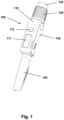
- Fig. 1 shows an embodiment of a drug delivery system comprising a pen-formed drug delivery unit and a data capture unit releasably attachable to each other.
- the drug delivery unit per se could be of any desirable design providing the necessary input to the data capture unit, however, the shown embodiment represents the type of pen in which a spring is loaded during setting of a dose, this allowing spring-driven drug expelling when the set and loaded mechanism is released by the user, this allowing a design in which the release (or actuation) button is axially stationary during dose setting.
- a more detailed description of such a pen can be found in e.g. US 2009/054839 , US 2008/306446 and US 2008/ 234634 .
- such a drug delivery device of the pen type comprises a proximal part having a mainly cylindrical housing portion with an expelling mechanism and a distal portion comprising a drug cartridge with an axially moveable piston driven by the expelling mechanism.
- the pen comprises a rotatable dose setting ring member allowing a user to set and adjust (i.e. dial-up and dial-down) a variable dose size of given increments (e.g. 1 IU insulin) to be expelled from the cartridge, the actual dose size (e.g. 25 IU insulin) being indicated by numbers shown in a window, the numbers being arranged on a rotating dose drum member.
- the maximum amount of drug that can be delivered during one out-dosing is defined by the injection device.
- the injection device may deliver variable dose amounts during one out-dosing between 1 IU insulin and 80 IU insulin.
- a push button is arranged at the proximal end and adapted to release the expelling mechanism when pushed distally by the user. As the mechanism is released the set dose will be expelled from the cartridge and the dose drum will correspondingly rotate back towards its initial zero position. If the mechanism is designed to stop expelling when the user stops pushing the release button, the number display in the window will show the portion of the dose (e.g. the numbers of units) not yet expelled, e.g. 10 units of insulin. Based on a drug delivery pen of the type described above fig.
- FIG. 1 shows an embodiment of a drug delivery system 100 comprising a pen-formed drug delivery unit and a data capture uni 110 the units being releasably attachable to each other.
- the system comprises a rotatable dose setting member 120 and a proximally arranged release button 130 adapted to be moved between an initial position, an intermediate position, and an actuated position in which the expelling means is actuated to expel the set dose.
- the distal reservoir part of the drug delivery device is covered by a cap member 150.
- the data capture unit 110 comprises electronic detection means for capturing data representing a property related to the amount of drug expelled from the reservoir by the expelling means (see below), and switch means for initiating data capture, the switch means being actuated when the release button is moved from its initial to its intermediate position.
- the data capture unit also comprises a display 111 adapted to show e.g. time and dose size for the last expelling action, as well as a key 112 allowing a user to e.g. toggle between a number of recent time-dose logs.
- the data capture unit may further be provided with an output port for wired or wireless upload of data to an external device, e.g. to the users smartphone or a doctors personal computer.
- an electronic data acquisition system could be based on the following concept: To save energy the system is dormant during non-use of the device as well as during setting of the dose. When the dose is thus set and the user actuates the release button this indicates to the system that the set dose is the actual dose to be captured. However, depending on the principle used to capture information about the set dose, the system may need time to "wake up” and capture dose information before the information "is gone", i.e. the only information representing the set (and expelled) dose is the position of mechanical components, e.g. the dose drum. This would for example be the case in a system based on optical detection of information arranged on member rotating during out-dosing (see below).
- the wake-up would have to take place during the time of travel for the release button between its initial position and the position in which the expelling mechanism is released, i.e. given such a travel is provided.
- the moving part may be a part of the out-dosing mechanism in the injection device itself, or a part in physical connection with a moving part in the out-dosing mechanism in the injection device (e.g. a mechanical or magnetic connection). The position of the moving part is related to the out-dosed amount.
- the optical detector/decoder is arranged in an add-on device to be mounted on or in the injection device.
- the following description of exemplary embodiments is based on a system where the optical detector is part of an add-on device to be mounted on or in an injection device.
- the optical detector/decoder is designed to be able to read a code pattern (or identifier) on a moving part.
- the position of the moving part is related to the amount of drug being out-dosed from the device, either by being an integrated part of the out-dosing mechanism in the injection device itself, or by having a physical connection with a moving part in the out-dosing mechanism in the injection device.
- the optical detector is arranged in a position relative to the moving part with the code pattern, where its field of view contains a portion of the code pattern.
- out-dosing from the injection device one or more elements of the internal out-dosing mechanism in the injection device is moved (or translated).
- elements of the out-dosing mechanism in the injection device move this will result in a related movement of the code pattern detectable by the optical detector/decoder.
- the part of the code pattern that is in the field of view of the optical detector changes as a consequence of the out-dosing.
- the code pattern is designed to be interpreted by the optical detector/decoder the changes of the code pattern in the field of view of the optical detector can be used to derive the position of the moving part when out-dosing starts and when out-dosing stops (and optionally during the out-dosing). Hence the out-dosing amount can be calculated and subsequently stored and/or communicated by the data acquisition system.
- the movement of the moving part with the code pattern may be rotational (around one or more axes), linear (in one or more directions) or a combination hereof.
- the code pattern may be either a discrete code (e.g. a binary code), where the code pattern changes instantly for each increment, or it may be an analogue (non-discrete) continuously changing code pattern (e.g. a grey scale code or a colour code, that changes floatingly from one tone/colour to another tone/colour).
- a discrete binary code where the values (0 or 1) are detected based on the intensity of light that reaches the optical detector/decoder.
- the optical detector must read the code value on the moving part with a time between readings that is fast enough to safely detect every time the code value changes (e.g. each out-dosing increment) during the movement of the moving part. If the code has more bits the time between readings can be prolonged and/or a system that is more robust towards e.g. tolerances may be designed. If the code has e.g. 7 bits a total of 128 different code values are possible. For an injection device with possible out-dosing amounts during one out-dosing event between e.g.
- the code pattern may be integrated on a moving part in multiple different ways.
- Examples of methods of producing detectable code patterns directly on the moving part that can be read by the optical detector/decoder system are: Printing on the moving part with different colours or tones of grey scale; providing areas on the moving part with dark tone and/or other areas with bright tone e.g. by means of printing, embossing or laser marking on areas; making areas on the moving part that reflects light towards the detector (e.g. by making surface concave or parallel with detector field of view) and/or other areas that reflects light away from the detector (e.g.
- the moving part by making surface convex or non-parallel with detector field of view or by making a rough surface texture); making holes, cut-outs or transparent areas at locations in the moving part that allows a direct passage of light through the holes/cut-outs/transparent areas to the optical detector and no passage or reduced passage of light outside the holes/cut-outs; making areas on the moving part with special optical properties (e.g. by adding an optical filter, by polarisation or by producing areas with different absorption of light or by producing areas that ensure diffuse reflection of light); making the movable part so it consists or two (or more) components, the two (or more) components having different optical characteristics (e.g.
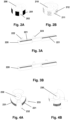
- Fig. 2A shows a rotatable part 200 with printed or laser marked areas 201 with dark colour and/or other areas 202 with bright colour, e.g. six areas with dark colour and six areas with bright colour.
- Fig. 2B shows a rotatable part 210 with areas of the structure which reflect light towards the optical detector/decoder and other areas which reflects light away from the optical detector/decoder, e.g. six areas 211 with concave surface that reflects light towards the optical detector/decoder and six areas 212 with rough surfaces that scatter or disperse light away from the optical detector/decoder.
- the code pattern may be placed on a continuous surface of the moving part, or it may be segmented onto multiple broken surfaces of the moving part. If the code pattern is placed on multiple broken surfaces of the moving part, additional optical detectors/decoders may be needed.
- Figs. 3A and 3B illustrate the principle of placing the code pattern on multiple broken surfaces 221 on a part 220 that moves linearly, such a system comprising two optical detectors/decoders 222, 223 securing that at least one detector/decoder will capture the moving code pattern.
- Figs. 4A and 4B illustrates the principle of placing the code pattern on multiple broken surfaces 231 on a part 230 that rotates, such a system also comprising two optical detectors/decoders 232, 233.
- the code pattern may be designed in multiple different ways. Examples of code patterns that can be read by an optical detector/decoder system are: Binary codes, i.e. codes with radix 2, e.g. designed as a code based on the binary number system, or as a binary-reflected Gray-code. A binary code with more than one bit may be produced by multiple code tracks, or by a single code track with multiple optical detectors/decoders, e.g. by the principle of quadrature encoding, or by a combination hereof; analogue (non-discrete) codes, e.g. designed as a grey scale code or as a colour tone code.
- Binary codes i.e. codes with radix 2
- a binary code with more than one bit may be produced by multiple code tracks, or by a single code track with multiple optical detectors/decoders, e.g. by the principle of quadrature encoding, or by a combination hereof
- analogue (non-discrete) codes e.g
- the optical detector/decoder and the moving part with the code pattern there may be an unobstructed passage of light or the passage of light may be limited by other structures e.g. a housing or a label material which is especially relevant in system designs where the moving part is integrated in the injection device itself and the optical detector/decoder is incorporated in an add-on device.
- the structure between the moving part with the code pattern and the optical detector/decoder can be modified by having an opening in the structure, or the material characteristics for the structure (e.g. a housing or a label) between the moving part with the special code pattern and the optical detector/decoder may be selected so it is sufficiently transparent for light to enable detection by the optical detector/decoder.
- the transparency may be limited to only relevant wave lengths, possibly being non-visual for the normal human eye.
- an add-on device may contain a system that penetrates the structure (e.g. a housing or a label) between the moving part with the code pattern and the optical detector/decoder before the time of detection, e.g. during mounting of the add-on device on or in the injection device.
- a mechanical part e.g. a lid, could be opened or removed from the device by the user.
- the moving part with the code pattern may either be an integrated part of the injection device, or it may be an integrated part of the add-on device. If the coded moving part is an integrated part of the add-on device, the coded moving part must be connected to a moving part of the out-dosing mechanism in the injection device, e.g. by use of a mechanical interface, e.g. gear wheels and/or belt drives.
- the out-dosing amount data acquisition system additionally comprises a triggering system that defines the relevant time for the optical detector/decoder to read the special code pattern on the moving part.
- the system may comprise a mechanically actuatable electro-mechanical switch detecting the position of a moving part of the out-dosing activation mechanism in the injection device, e.g. a user actuated push button and/or an element which position is related to the position or state of the user actuated push button.
- an electromechanical switch may detect when the out-dosing activation mechanism is in a state immediately before the actual out-dosing starts (corresponding to the above-described intermediate position), and immediately after the out-dosing stops.
- the optical detector/decoder When activated the optical detector/decoder reads the code pattern on the moving part immediately before the actual out-dosing starts, and immediately after the out-dosing stops, and optionally also a number of times in the time period between start and stop of the actual out-dosing. Based on these readings the out-dosed amount of drug can be calculated.
- the system comprises an optical trigger system comprising one or more optical detectors that detect when the injection device is about to enter the out-dosing state.
- the detection of whether the injection device is in the out-dosing state may be performed by means of an optical detector that detects the position of a moving part of the out-dosing mechanism (and/or of a part which position is related to the position or state of a part of the out-dosing mechanism) and/or of a moving part of the out-dosing activation mechanism in the injection device, e.g. a user actuated push button and/or a part which position is related to the position or state of the user actuated push button.
- the optical detector may detect when the out-dosing activation mechanism is in a state immediately before the actual out-dosing starts, and immediately after the out-dosing stops.
- the optical detector may detect when the out-dosing activation mechanism is in a state immediately before the actual out-dosing starts, and immediately after the out-dosing stops.
- the time interval between the readings by the optical detector is set so it ensures timely start-up of the optical out-dosing detector/decoder system, to safely determine the out-dosed amount.
- the energy consumption by an optical-based trigger system should be low, resulting in a low impact on the total power consumption of the total trigger and out-dosing amount acquisition system.
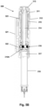
- Fig. 5A illustrates an example of a specific embodiment of a system 300 where an add-on device 320 (shown in axial cross-section) is mounted on a pen-formed device 310.
- the drug delivery device comprises a rotatable dose setting member 311 and a proximally arranged release button 313 adapted to be moved between an initial position, an intermediate position, and an actuated position in which the expelling means is actuated to expel the set dose.
- a drug reservoir in the form of a cartridge 318 is arranged in the distal part of the drug delivery device.
- the cartridge holder 318A may be permanently fixed to the pen housing as in a pre-filled device, or it may be releasable mounted allowing a user to replace a drug cartridge.
- the data capture unit 320 comprises a housing 321 comprising electronic detection means for capturing data representing a property related to the amount of drug expelled from the reservoir by the expelling means (see below), and switch means for initiating data capture, the switch means being actuated when the release button is moved from its initial to its intermediate position.
- Fig. 5B shows a longitudinal cross-sectional view of the system of fig. 5A .
- the optical detector/decoder is an integrated part of an add-on device to be mounted on an injection device.
- the injection device is of the type shown in US 2008/306446 in which the expelling mechanism comprises a piston rod 314 adapted to move a piston 317 forward in a container 318, a spring 315 as well as a member 316 which is rotationally stationary during setting of a dose and the corresponding straining of the spring (e.g. by being coupled to the housing) but which can be released from this rotationally locked position when the expelling mechanism is released, this allowing the member to rotate during expelling of a dose.
- such a member is an "active" element serving to transfer energy from the spring strained during the dose-setting action and to the piston rod pushing the reservoir piston during expelling of a dose of drug.
- the expelling mechanism is released by axially depressing a proximally arranged release button, this directly or indirectly resulting in the release of a coupling allowing the mechanism to expel the set amount of drug.
- the actuation of the release button between its different positions allows the detection means to be energized prior to begin of the out-dosing action per se.
- the rotating part 316 is an integrated part of the out-dosing mechanism in the injection device, and the angle of rotation of the rotating part is proportional with the out-dosed amount of drug, e.g. 15° rotation of the rotating part corresponds to 1 IU insulin being out-dosed.
- the user-actuated push button moves axially downwards when it is pushed.
- the movement of the user actuated push button has a mechanical coupling to an internal part of the out-dosing activation mechanism inside the injection device, which also moves axially downwards when the user-actuated push button is pressed.
- an electromechanical trigger switch 323 engages, via a circumferential gap 312 between the dose dial ring 311 and the pen body, the user-actuated push button and is activated when the user pushes down the button 313.
- the push button serves to provide an indicator portion for actuating the switch means.
- the trigger switch is activated a signal is sent to the optical detector/decoder system which subsequently starts to detect and decode the code pattern 316A printed on a rotating cylindrical ring member 316 of the out-dosing mechanism in the injection device.
- the optical detector/decoder 322 recognizes the optical code through an opening 319 (see fig. 5A ) in the housing of the injection device.
- the detection and decoding may be performed at a given frequency until the electromechanical switch is deactivated, e.g. when the user releases the user actuated push button.
- the code pattern on the moving part 316 is a single track code with six dark areas and six light areas as shown in fig. 2A .
- Two optical detectors/decoders are placed with 15° between them, resulting in a 2 bit binary-reflected Gray-code signal by use of quadrature encoding.
- the value of the Gray-code changes when the rotating part has been rotated 15°.
- the optical detectors/decoders detect and encode the code pattern at a frequency that is fast enough to register and count every time the rotating part with the special code pattern has rotated 15°.
- the optical detector/decoder counts the number of times the value of the Gray-code successively has changed step by step, and hereby the out-dosing amount of drug can be calculated from the time that the electro-mechanical switch has been activated to the time that the electromechanical switch is deactivated or end of out-dosing is captured by other means.
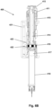
- Figs. 6A and 6B illustrate in an alternative embodiment a system 400 with a pen-formed drug delivery device 410 and an add-on unit 420 in which the electromechanical trigger switch 423 is instead activated by an inner component in the injection device through an opening 419 in the housing, which movement is mechanically coupled to the user actuated push button 413 on the injection device.
- the two systems of figs. 5 and 6 are otherwise or near-identical.
- Figs. 7A and 7B illustrate a further embodiment of a system 500 in which the optical detector/decoder is an integrated part of an add-on device 520 to be mounted on an injection device 510 of the same general design as the embodiments of figs. 6 and 7 , i.e. having a part 516 that rotates proportionally with a given member of the expelling mechanism during out-dosing of the drug, the part being released by a push button 513 that the user presses in order to activate the out-dosing mechanism in the injection device.
- a code pattern 526 is printed on a cylindrical "code wheel" 525 formed as an integrated part of the add-on device.
- the code wheel rotates due to a mechanical coupling, e.g. gearwheel, to a rotating part 516 of the out-dosing mechanism in the injection device.
- the value of the code pattern changes every time the rotating part of the out-dosing mechanism has rotated e.g. 15° corresponding to 1 IU.
- the add-on device contains a trigger system as described above (not shown) that detects when the user actuates the release button and thus initiates data capture.
- the gearing may be 1 to 4.
- all possible out-dosing amounts between 0 IU insulin to 95 IU insulin may be registered during less than 1 full rotation of the code wheel, every increment (corresponding to 3.75° on the code wheel) thus having a dedicated "absolute" code value, this in contrast to the above relative detection mode.
- the out-dosed amount of drug can be calculated based on an end-reading from the previous out-dosing.
- the triggering action could be based on initial capture of dose wheel movement, the determination of the out-dosed amount being based on the "absolute" position of the dose wheel at the end of the out-dosing action, e.g. either based on a triggering action or by a determination that the dose wheel has not moved for a given amount of time.
- a data capture system having low energy consumption in sleep mode as no separate wake-up triggering would be provided.
- the above-described embodiments are based on an arrangement in which the optical detector/decoder is fixed and the moving part with the code pattern moves relative to the detector.
- the code pattern 611 could be fixed, e.g. printed on the device housing 610, and the optical detector/decoder 612 could move relative to the code pattern.
- the optical detector/decoder could be physically connected, e.g. by a mechanical connection, with a moving part of the out-dosing mechanism.
- both the code pattern 621, 631 and the optical detector/decoder 622, 632 may be fixed.
- the field of view of the optical detector/decoder contains the entire code pattern, but it is only possible to read the code pattern for a specific area of the code.
- a third movable element e.g. a frame 623 or a light source 633 defines the readable area and moves during out-dosing.
- the third movable element that defines the readable area would be connected with a moving part of the out-dosing mechanism.
- the system 700 comprises a pen-formed drug delivery device 710 and an add-on assembly provided as two units, one unit 720 containing the data capture means and adapted to be coupled to the pen body, and one unit 750 containing an electronic display 751, the latter also serving as a cap for the drug deliver device.
- the two parts have means to communicate with each other (by wire or wirelessly) whereby the add-on display part is able to display information sent to it from the add-on device part.
- the display may be in the form of a flexible tag device comprising no battery (i.e. electrochemical cell) with receiving means adapted to receive RF signals also used to energize the display controller.
- the display may be based on mono-chromatic or colour e-ink paper or another bi-stable display technology.
- the display part can be an autonomous accessory device in itself with its own self-contained functions, e.g. a blood glucose meter (BGM) in a pen cap 760 adapted to receive BG test strips 762, and adapted to communicate with an add-on accessory on or in an injection device (or alternatively integrated into a pen body) in order to receive data and display information based on these on its electronic display 761.
- BGM blood glucose meter
- the pen cap may have other functions, e.g. a pen cap with an electromechanical interface and electronics able to sense if it has been dismounted from the pen and a display to show derived information thereof.
- a pen cap with an electromechanical interface and electronics able to sense if it has been dismounted from the pen and a display to show derived information thereof.
- the two parts have means to communicate with each other whereby the display accessory part is able to display information sent from the injection devices add-on device part on its electronic display.
Landscapes
- Health & Medical Sciences (AREA)
- Engineering & Computer Science (AREA)
- Public Health (AREA)
- General Health & Medical Sciences (AREA)
- Biomedical Technology (AREA)
- Medical Informatics (AREA)
- Primary Health Care (AREA)
- Epidemiology (AREA)
- Animal Behavior & Ethology (AREA)
- Anesthesiology (AREA)
- Vascular Medicine (AREA)
- Life Sciences & Earth Sciences (AREA)
- Veterinary Medicine (AREA)
- Hematology (AREA)
- Heart & Thoracic Surgery (AREA)
- Chemical & Material Sciences (AREA)
- Bioinformatics & Cheminformatics (AREA)
- Medicinal Chemistry (AREA)
- Business, Economics & Management (AREA)
- General Business, Economics & Management (AREA)
- Infusion, Injection, And Reservoir Apparatuses (AREA)
Claims (11)
- Système d'administration de médicament (300) comprenant :- un moyen d'expulsion (314, 315) pour l'expulsion d'une quantité de médicament d'un réservoir (318), comprenant :(a) un moyen de réglage (311) permettant à un utilisateur de régler une quantité de dosage de médicament à expulser, et(b) un moyen d'actionnement (313) pour la libération ou l'entraînement du moyen d'expulsion de médicament afin d'expulser la quantité de dosage réglée,- un système de capture commandé électroniquement (320) pour la capture de données représentant une propriété liée à la quantité de médicament expulsée d'un réservoir par les moyens d'expulsion, et- un moyen de commutation (323) pour le démarrage de l'initialisation du système de capture,dans lequel le moyen d'actionnement comprend un élément d'actionnement (313) adapté pour être déplacé entre :(i) une position initiale,(ii) une position intermédiaire dans laquelle le moyen de commutation est actionné afin de démarrer l'initialisation du système de capture, et(iii) une position actionnée dans laquelle le moyen d'expulsion est actionné afin d'expulser la dose réglée,moyennant quoi le système de capture est autorisé à s'initialiser pendant le mouvement de l'élément d'actionnement entre la position intermédiaire et la position actionnée,le système d'administration de médicament comprenant une unité d'administration de médicament et une unité de capture de données pouvant être attachées de manière amovible l'une l'autre, l'unité d'administration de médicament comprenant :- les moyens d'expulsion de médicament,- les moyens de réglage, et- les moyens d'actionnement,l'unité de capture de données comprenant :- le système de capture commandé électroniquement, et- les moyens de commutation.
- Système d'administration de médicament selon la revendication 1, comprenant une première portion d'indicateur (313) qui se déplace lorsque l'élément d'actionnement est déplacé de sa position initiale à sa position intermédiaire.
- Système d'administration de médicament selon la revendication 2, dans lequel la première portion d'indicateur est déplacée linéairement lorsque l'élément d'actionnement est déplacé de sa position initiale à sa position intermédiaire.
- Système d'administration de médicament selon la revendication 2 ou 3, dans lequel le moyen de commutation comprend un moyen de capteur optique adapté à la détection lorsque la première portion d'indicateur est déplacée en correspondance avec le déplacement de l'élément d'actionnement vers sa position intermédiaire.
- Système d'administration de médicament selon la revendication 2 ou 3, dans lequel le moyen de commutation comprend un commutateur mécanique (323, 423) adapté pour être actionné lorsque la première portion d'indicateur est déplacée en correspondance avec le déplacement de l'élément d'actionnement vers sa position intermédiaire.
- Système d'administration de médicament selon l'une quelconque des revendications 1 à 5, dans lequel le moyen d'expulsion comprend un identifiant (316A) associé à une deuxième portion d'indicateur (316) qui se déplace pendant l'expulsion du médicament et représente une propriété liée à la quantité de médicament expulsée d'un réservoir par le moyen d'expulsion, le système de capture étant adapté à la capture de l'identifiant.
- Système d'administration de médicament selon la revendication 6, dans lequel la deuxième portion indicatrice se déplace en rotation pendant l'expulsion du médicament.
- Système d'administration de médicament selon la revendication 6 ou 7, dans lequel- le système de capture comprend un moyen de capteur optique (322), et- l'identifiant (316A) est adapté pour être capturé par le moyen de capteur optique.
- Système d'administration de médicament selon la revendication 1, dans lequel- l'unité de capture de données comprend en outre un moyen de transmission pour la transmission sans fil des données capturées, et- le système d'administration de médicament comprend en outre une unité de capuchon pouvant être montée de manière amovible sur l'unité d'administration de médicament, comprenant :(i) un moyen de réception pour la réception des données capturées depuis l'unité de capture de données, et(ii) un moyen d'affichage adapté à l'affichage d'une valeur correspondant aux données capturées.
- Système d'administration de médicament selon l'une quelconque des revendications 1 à 9, comprenant un réservoir de médicament.
- Système d'administration de médicament selon l'une quelconque des revendications 1 à 9, le système étant configuré pour recevoir un réservoir de médicament remplaçable sous la forme d'une cartouche de médicament.
Priority Applications (1)
| Application Number | Priority Date | Filing Date | Title |
|---|---|---|---|
| EP12735504.8A EP2729202B2 (fr) | 2011-07-07 | 2012-07-09 | Injecteur de type stylo avec module de mesure et d'affichage de dose |
Applications Claiming Priority (4)
| Application Number | Priority Date | Filing Date | Title |
|---|---|---|---|
| EP11173080 | 2011-07-07 | ||
| US201161507222P | 2011-07-13 | 2011-07-13 | |
| PCT/EP2012/063350 WO2013004844A1 (fr) | 2011-07-07 | 2012-07-09 | Stylo d'injection de médicament doté d'un module de capture et d'affichage de dose auxiliaire |
| EP12735504.8A EP2729202B2 (fr) | 2011-07-07 | 2012-07-09 | Injecteur de type stylo avec module de mesure et d'affichage de dose |
Publications (3)
| Publication Number | Publication Date |
|---|---|
| EP2729202A1 EP2729202A1 (fr) | 2014-05-14 |
| EP2729202B1 EP2729202B1 (fr) | 2018-05-16 |
| EP2729202B2 true EP2729202B2 (fr) | 2024-11-06 |
Family
ID=47436555
Family Applications (1)
| Application Number | Title | Priority Date | Filing Date |
|---|---|---|---|
| EP12735504.8A Active EP2729202B2 (fr) | 2011-07-07 | 2012-07-09 | Injecteur de type stylo avec module de mesure et d'affichage de dose |
Country Status (5)
| Country | Link |
|---|---|
| US (1) | US9623188B2 (fr) |
| EP (1) | EP2729202B2 (fr) |
| JP (1) | JP6106666B2 (fr) |
| CN (1) | CN103702699B (fr) |
| WO (1) | WO2013004844A1 (fr) |
Families Citing this family (125)
| Publication number | Priority date | Publication date | Assignee | Title |
|---|---|---|---|---|
| JP6616073B2 (ja) | 2011-03-24 | 2019-12-04 | サノフィ−アベンティス・ドイチュラント・ゲゼルシャフト・ミット・ベシュレンクテル・ハフツング | 医療デバイスで実行可能な作動動作を検出するためのデバイス及び方法 |
| JP6109834B2 (ja) | 2011-10-07 | 2017-04-05 | ノボ・ノルデイスク・エー/エス | 3軸磁気センサに基づいて要素の位置を決定するシステム |
| KR20140122272A (ko) * | 2012-02-13 | 2014-10-17 | 사노피-아벤티스 도이칠란트 게엠베하 | 주사 장치 부착용 보조 장치 |
| KR20130140301A (ko) | 2012-06-14 | 2013-12-24 | 삼성전자주식회사 | 주사량 측정 장치 |
| CN104519930B (zh) * | 2012-08-03 | 2017-11-07 | 赛诺菲-安万特德国有限公司 | 笔型药物注射装置和用于监视和记录剂量设定与给药日志的电子附加监视模块 |
| US11872375B2 (en) | 2012-09-05 | 2024-01-16 | E3D Agricultural Cooperative Association Ltd. | Electronic auto-injection device |
| JP6366607B2 (ja) | 2013-01-15 | 2018-08-01 | サノフィ−アベンティス・ドイチュラント・ゲゼルシャフト・ミット・ベシュレンクテル・ハフツング | 注射デバイスの使用についての使用レポートをデジタル画像形式で生成するために医療注射デバイスに取り付ける補助デバイス |
| DK2945671T3 (da) | 2013-01-15 | 2021-07-05 | Sanofi Aventis Deutschland | Pennelignende anordning til indgivelse af lægemidler med friktionsreducerende dosisindkodningsmekanisme |
| US10112017B2 (en) | 2013-01-15 | 2018-10-30 | Sanofi-Aventis Deutschland Gmbh | Pen type drug injection device with low friction dose encoder mechanism on thread |
| WO2014111336A1 (fr) * | 2013-01-15 | 2014-07-24 | Sanofi-Aventis Deutschland Gmbh | Dispositif d'injection de médicament de type stylo et module de surveillance auxiliaire électronique pour surveiller et enregistrer le réglage et l'administration de dose |
| JP6411369B2 (ja) * | 2013-01-15 | 2018-10-24 | サノフィ−アベンティス・ドイチュラント・ゲゼルシャフト・ミット・ベシュレンクテル・ハフツング | 復号システム |
| EP3248637B1 (fr) * | 2013-01-15 | 2020-11-04 | Sanofi-Aventis Deutschland GmbH | Méthode optique pour décoder une dose |
| DK2945670T3 (en) * | 2013-01-15 | 2018-02-26 | Sanofi Aventis Deutschland | PHARMACEUTICAL INJECTION DEVICE OF THE PENY TYPE WITH DOSAGE CODE MECHANISM AND SWITCHES BETWEEN DOSAGE SETTING AND DOSAGE DISPENSING CONDITIONS |
| EP2945674B1 (fr) * | 2013-01-15 | 2017-03-08 | Sanofi-Aventis Deutschland GmbH | Injecteur de médicament de type stylo avec détecteur de dosage pour déterminer la position absolue angulaire d'un élément de dosage |
| CN104902944B (zh) | 2013-01-15 | 2018-10-26 | 赛诺菲-安万特德国有限公司 | 具有用以在剂量拨选模式和剂量输送模式之间进行区分的额外传感器的笔型药物输送装置和光学剂量值解码系统 |
| WO2014128157A1 (fr) | 2013-02-19 | 2014-08-28 | Novo Nordisk A/S | Dispositif d'administration de médicament avec module de capture de dose |
| EP2958610B1 (fr) * | 2013-02-19 | 2016-11-30 | Novo Nordisk A/S | Dispositif d'administration de médicament avec module de capture de dose dans une cartouche |
| CN105120925B (zh) * | 2013-04-05 | 2018-11-06 | 诺和诺德股份有限公司 | 药物输送设备和记录模块组件 |
| EP2981310B1 (fr) | 2013-04-05 | 2017-07-12 | Novo Nordisk A/S | Dispositif d'enregistrement de dose destiné à un dispositif d'administration de médicament |
| CN105102024B (zh) * | 2013-04-05 | 2019-02-05 | 诺和诺德股份有限公司 | 适合于将剂量组合的记录设备 |
| JP6756806B2 (ja) * | 2013-04-05 | 2020-09-16 | ノボ・ノルデイスク・エー/エス | 複数の用量を合算するロギング装置 |
| CN105120927B (zh) * | 2013-04-22 | 2019-02-01 | 赛诺菲-安万特德国有限公司 | 用于收集与注射装置的使用有关的信息的辅助装置 |
| CN105228678B (zh) | 2013-04-22 | 2019-09-27 | 赛诺菲-安万特德国有限公司 | 具有oled的传感器装置 |
| JP6781629B2 (ja) * | 2013-04-22 | 2020-11-04 | サノフィ−アベンティス・ドイチュラント・ゲゼルシャフト・ミット・ベシュレンクテル・ハフツング | 薬剤送達デバイスへの取付けのためのセンサデバイス |
| EP2988805B1 (fr) * | 2013-04-22 | 2022-01-05 | Sanofi-Aventis Deutschland GmbH | Dispositif supplémentaire destiné à être utilisé avec un dispositif d'injection, procédé de fonctionnement de celui-ci et programme informatique permettant de commander un dispositif supplémentaire pour effectuer le procédé |
| EP2994179B1 (fr) * | 2013-05-07 | 2018-03-14 | Sanofi-Aventis Deutschland GmbH | Dispositif supplémentaire pour fixation sur un dispositif d'injection |
| US10226577B2 (en) | 2013-11-13 | 2019-03-12 | Novo Nordisk A/S | Drug delivery device with time indicator feature |
| US11311678B2 (en) | 2013-11-21 | 2022-04-26 | Novo Nordisk A/S | Rotary sensor assembly with space efficient design |
| JP6786389B2 (ja) | 2013-11-21 | 2020-11-18 | ノボ・ノルデイスク・エー/エス | 軸方向スイッチおよび冗長化機構を備えた回転センサアセンブリ |
| WO2015103784A1 (fr) * | 2014-01-13 | 2015-07-16 | 深圳市祥涛瑞杰贸易有限公司 | Structure de surveillance d'informations d'injection de médicament, et système et injecteur de médicament de cette dernière |
| CN106104576B (zh) | 2014-01-24 | 2019-11-26 | 赛诺菲-安万特德国有限公司 | 用于附接到注射装置使用光学字符识别(ocr)记录和显示用户设定的剂量值的辅助装置 |
| CN106456884A (zh) * | 2014-03-14 | 2017-02-22 | 卡贝欧洲有限公司 | 监测装置 |
| CN106659842B (zh) | 2014-06-06 | 2019-12-24 | 诺和诺德股份有限公司 | 用于药物输送设备的记录设备 |
| CN106413781B (zh) * | 2014-06-06 | 2020-04-21 | 诺和诺德股份有限公司 | 由药物输送设备操作的记录设备 |
| DK3155378T3 (da) * | 2014-06-10 | 2019-08-19 | Sanofi Aventis Deutschland | Sensoranordning, der kan fastgøres aftageligt til en lægemiddeladministrationsanordning |
| CA2952167C (fr) | 2014-06-13 | 2023-06-13 | Aterica Inc. | Systeme et dispositif de gestion de dispositifs d'administration de medicaments |
| US10384014B2 (en) | 2014-09-02 | 2019-08-20 | Eli Lilly And Company | Sensing system for detecting a piston in a medical fluid container |
| US10704944B2 (en) | 2014-09-14 | 2020-07-07 | Becton, Dickinson And Company | System and method for capturing dose information |
| US10971260B2 (en) | 2014-09-14 | 2021-04-06 | Becton, Dickinson And Company | System and method for capturing dose information |
| WO2016050902A1 (fr) * | 2014-10-03 | 2016-04-07 | Novo Nordisk A/S | Injecteur de médicament de type stylo et module d'extension ayant un système de capteur de dosage magnétique et une détection d'erreur |
| WO2016062807A1 (fr) * | 2014-10-23 | 2016-04-28 | Novo Nordisk A/S | Dispositif d'administration de médicament de type stylo avec affichage électronique sur élément d'attache |
| EP3242698A1 (fr) * | 2015-01-08 | 2017-11-15 | Novo Nordisk A/S | Dispositif d'injection de médicament ayant un système d'indicateur de fin de contenu visuel |
| EP3045186A1 (fr) | 2015-01-16 | 2016-07-20 | Sanofi-Aventis Deutschland GmbH | Capteur à utiliser avec un dispositif d'administration de médicaments |
| EP3247428B1 (fr) * | 2015-01-21 | 2024-04-10 | Sanofi-Aventis Deutschland GmbH | Dispositif supplémentaire pour fixation sur un dispositif d'injection pour déterminer dose de médicament utilisant capteur optique de l'accroissement arbitraire |
| EP3058973A1 (fr) * | 2015-02-19 | 2016-08-24 | Sanofi-Aventis Deutschland GmbH | Dispositif supplémentaire pour une fixation amovible à un dispositif d'injection de médicament |
| EP3058970A1 (fr) | 2015-02-19 | 2016-08-24 | Sanofi-Aventis Deutschland GmbH | Dispositif de collecte de données destiné à être fixé à un dispositif d'injection |
| WO2016138634A1 (fr) * | 2015-03-03 | 2016-09-09 | 创新精密仪器有限公司 | Appareil de surveillance d'informations de médicament et appareil du type à injection de surveillance d'informations de médicament |
| CN104800932B (zh) * | 2015-03-03 | 2017-11-10 | 创新精密仪器有限公司 | 药物信息监测装置和药物信息监测式注射装置 |
| PL3265152T3 (pl) * | 2015-03-06 | 2020-08-10 | Attila BEREY | Środki do pozyskiwania danych, zwłaszcza do urządzenia do podawania leków typu wstrzykiwacz |
| EP3067081A1 (fr) * | 2015-03-12 | 2016-09-14 | Sanofi | Dispositif d'administration de médicaments |
| JP2018515232A (ja) * | 2015-05-12 | 2018-06-14 | ノボ・ノルデイスク・エー/エス | 薬剤送達装置のための回転センサ構造体 |
| WO2016191820A1 (fr) * | 2015-06-02 | 2016-12-08 | Newsouth Innovations Pty Limited | Formulation et procédé pour limiter un traumatisme nerveux |
| JP6901975B2 (ja) | 2015-06-09 | 2021-07-14 | サノフィ−アベンティス・ドイチュラント・ゲゼルシャフト・ミット・ベシュレンクテル・ハフツング | 注射デバイスに取り付けられるデータ収集装置 |
| PL3419700T3 (pl) * | 2015-07-21 | 2024-03-04 | Biocorp Production S.A. | Urządzenie sterujące dawką dla urządzeń do dostarczania leków do wstrzykiwań |
| ES2954088T3 (es) | 2015-07-21 | 2023-11-20 | Biocorp Production SA | Sistema de control de dosis para dispositivos de administración de fármacos inyectables y métodos de uso asociados |
| EP3135330A1 (fr) * | 2015-08-24 | 2017-03-01 | Carebay Europe Ltd. | Unité de surveillance |
| WO2017032586A1 (fr) * | 2015-08-24 | 2017-03-02 | Carebay Europe Ltd | Unité de surveillance |
| US10576207B2 (en) | 2015-10-09 | 2020-03-03 | West Pharma. Services IL, Ltd. | Angled syringe patch injector |
| US10332699B2 (en) | 2015-09-30 | 2019-06-25 | Novo Nordisk A/S | Power efficient add-on device |
| JP7017512B2 (ja) | 2015-10-09 | 2022-02-08 | ウェスト ファーマ サービシーズ イスラエル リミテッド | 充填済流体容器の屈曲流体路型付属物 |
| CN106610449B (zh) * | 2015-10-23 | 2023-03-24 | 福建三洲电力科技有限公司 | 一种避雷器用二进制雷击计数装置 |
| JP6837483B2 (ja) * | 2015-11-11 | 2021-03-03 | ノボ・ノルデイスク・エー/エス | 情報の捕捉を伴う薬剤送達装置 |
| EP3178507A1 (fr) * | 2015-12-09 | 2017-06-14 | Carebay Europe Ltd. | Dispositif de communication pour transmettre des informations à partir d'un dispositif d'administration de médicament |
| EP3386569B1 (fr) * | 2015-12-10 | 2025-08-13 | Sanofi-Aventis Deutschland GmbH | Dispositif d'administration de médicament avec dispositif de détection pouvant être fixé de manière amovible |
| EP3184137A1 (fr) * | 2015-12-23 | 2017-06-28 | Carebay Europe Ltd. | Dispositif d'administration de médicament avec capacité de rétroaction d'utilisateur |
| CN109219458B (zh) * | 2016-01-21 | 2021-03-02 | 西医药服务以色列有限公司 | 包括视觉指示物的药剂传输装置 |
| US11311674B2 (en) | 2016-01-21 | 2022-04-26 | West Pharma. Services IL, Ltd. | Medicament delivery device comprising a visual indicator |
| WO2017132577A1 (fr) | 2016-01-29 | 2017-08-03 | Companion Medical, Inc. | Suivi automatique d'administration de médicament |
| JP7201435B6 (ja) | 2016-03-01 | 2023-01-23 | ノボ・ノルデイスク・エー/エス | 電力効率の良いアクセサリデバイス |
| EP3222309A1 (fr) | 2016-03-22 | 2017-09-27 | Carebay Europe Ltd | Unité de surveillance |
| EP3448470B1 (fr) | 2016-04-29 | 2020-03-18 | Novo Nordisk A/S | Système de livraison de médicament ayant captage de dosage |
| CN109152884B (zh) * | 2016-05-30 | 2022-02-11 | 诺和诺德股份有限公司 | 具有零位置调节特征的药物输送装置 |
| JP6722774B2 (ja) * | 2016-06-16 | 2020-07-15 | エス・ハー・エル・メディカル・アクチェンゲゼルシャフトShl Medical Ag | 薬剤送達装置のための補助装置 |
| US11554221B2 (en) | 2016-07-15 | 2023-01-17 | Eli Lilly And Company | Dose detection module for a medication delivery device |
| US9636464B1 (en) * | 2016-08-01 | 2017-05-02 | Innovative Precision Instruments Limited | Drug delivery device and a drug information detection device |
| WO2018036938A1 (fr) | 2016-08-26 | 2018-03-01 | Sanofi-Aventis Deutschland Gmbh | Dispositif pour la fixation à un dispositif d'injection |
| CN108066849A (zh) * | 2016-11-15 | 2018-05-25 | 广东东阳光药业有限公司 | 一种自动采集刻度数据的注射器 |
| CN110430907B (zh) * | 2017-01-13 | 2022-10-11 | 西医药服务有限公司 | 用于监视患者依从性的便携式设备 |
| CN108345396B (zh) * | 2017-01-25 | 2021-06-04 | 禾伸堂企业股份有限公司 | 具磁感应滚轮的触控笔及其操作方法 |
| RS67428B1 (sr) | 2017-02-28 | 2025-12-31 | Lilly Co Eli | Detekcija doze i identifikacija leka za uređaj za isporuku leka |
| US20190054251A1 (en) * | 2017-08-17 | 2019-02-21 | Qualcomm Incorporated | Medicine delivery device |
| ES2985951T3 (es) | 2017-08-18 | 2024-11-07 | Lilly Co Eli | Módulo de medición de dosificación en pluma inyectora |
| ES2996276T3 (en) | 2017-08-21 | 2025-02-12 | Lilly Co Eli | Dose detection module for a medication delivery device |
| MX2020005338A (es) | 2017-11-23 | 2020-10-14 | Sanofi Sa | Dispositivo de inyección de medicamento con codificador rotatorio. |
| US10987464B2 (en) | 2017-12-12 | 2021-04-27 | Bigfoot Biomedical, Inc. | Pen cap for insulin injection pens and associated methods and systems |
| AU2018383743A1 (en) | 2017-12-12 | 2020-07-23 | Bigfoot Biomedical, Inc. | Therapy assist information and/or tracking device and related methods and systems |
| US11083852B2 (en) | 2017-12-12 | 2021-08-10 | Bigfoot Biomedical, Inc. | Insulin injection assistance systems, methods, and devices |
| US11077243B2 (en) | 2017-12-12 | 2021-08-03 | Bigfoot Biomedical, Inc. | Devices, systems, and methods for estimating active medication from injections |
| US11116899B2 (en) | 2017-12-12 | 2021-09-14 | Bigfoot Biomedical, Inc. | User interface for diabetes management systems and devices |
| US11464459B2 (en) | 2017-12-12 | 2022-10-11 | Bigfoot Biomedical, Inc. | User interface for diabetes management systems including flash glucose monitor |
| US11197964B2 (en) | 2017-12-12 | 2021-12-14 | Bigfoot Biomedical, Inc. | Pen cap for medication injection pen having temperature sensor |
| US11738153B2 (en) | 2017-12-18 | 2023-08-29 | Patients Pending Ltd. | Liquid delivery cap devices, systems, and methods |
| WO2019121449A1 (fr) * | 2017-12-18 | 2019-06-27 | Sanofi | Dispositif d'enregistrement de dose |
| CN111565779A (zh) * | 2017-12-28 | 2020-08-21 | 赛诺菲 | 剂量测量系统 |
| AU2018394953B2 (en) * | 2017-12-29 | 2021-05-06 | Genentech, Inc. | Injection monitoring device with delivery signature |
| AU2019208338B2 (en) | 2018-01-19 | 2024-11-07 | Birya Biotech, Inc. | Tool for servicing an auto-injector |
| SI3755404T1 (sl) | 2018-02-22 | 2023-11-30 | Eli Lilly And Company | Modul sistema za zaznavanje odmerka za napravo za dostavo zdravila |
| TW202010527A (zh) * | 2018-08-31 | 2020-03-16 | 榮晶生物科技股份有限公司 | 劑量紀錄裝置及劑量紀錄方法 |
| US11229749B2 (en) | 2018-09-06 | 2022-01-25 | Verily Life Sciences Llc | Plate capacitor for dosage sensing |
| US12205699B1 (en) | 2018-10-30 | 2025-01-21 | Bigfoot Biomedical, Inc. | Method of pairing therapy devices using shared secrets, and related systems, methods and devices |
| JP2022512884A (ja) * | 2018-11-06 | 2022-02-07 | ノボ・ノルデイスク・エー/エス | 特徴をサンプリングするセンサを有する薬剤送達アセンブリ |
| US11948671B2 (en) | 2019-04-11 | 2024-04-02 | Medtronic Minimed, Inc. | Intelligent accessories for medicine dispensing device |
| US20220226583A1 (en) * | 2019-06-13 | 2022-07-21 | Sanofi | Apparatus for Detecting a Dose of Medicament Delivered from an Injection Device |
| JP7551662B2 (ja) | 2019-06-13 | 2024-09-17 | サノフイ | 薬物送達システムのための電子制御式取込みシステム |
| CH714994A2 (de) | 2019-08-20 | 2019-11-15 | Tecpharma Licensing Ag | Elektronikmodul mit Sensoreinheit und Injektionssystem. |
| CA3161462A1 (fr) * | 2019-11-13 | 2021-05-20 | Janssen Biotech, Inc. | Modules de detection de dispositif d'administration de medicament |
| CN115297915B (zh) | 2020-03-27 | 2025-11-07 | 赛诺菲 | 用于药物递送装置的电子系统 |
| WO2021191329A1 (fr) | 2020-03-27 | 2021-09-30 | Sanofi | Système électronique pour un dispositif d'administration de médicament |
| EP4000670A1 (fr) | 2020-11-16 | 2022-05-25 | Sanofi | Système électronique et procédé de détermination de défaillance d'un second commutateur dans un dispositif d'administration de médicaments |
| CN115315286B (zh) | 2020-03-27 | 2025-11-28 | 赛诺菲 | 用于药物递送装置的电子系统的开关组装件 |
| WO2021191325A1 (fr) | 2020-03-27 | 2021-09-30 | Sanofi | Système électronique pour un dispositif d'administration de médicament |
| US20230330345A1 (en) | 2020-03-27 | 2023-10-19 | Sanofi | Drug delivery device with electronic system |
| JP2023532586A (ja) * | 2020-07-08 | 2023-07-28 | ノボ・ノルデイスク・エー/エス | アルゴリズム自動較正を有する用量設定センサ組立品 |
| AU2021309966A1 (en) | 2020-07-15 | 2023-02-09 | Biogen Ma Inc. | Medical system including two access ports |
| US20230263959A1 (en) * | 2020-08-04 | 2023-08-24 | Sanofi | Drug delivery device and module herewith |
| JP2024505593A (ja) * | 2021-02-09 | 2024-02-06 | サノフイ | 用量計数システム |
| EP4326364A1 (fr) | 2021-04-23 | 2024-02-28 | Sanofi | Module de codeur électronique et dispositif d'administration de médicament comprenant celui-ci |
| CN118355250A (zh) * | 2021-09-24 | 2024-07-16 | 赛诺菲 | 用于药物输送装置的测量系统、具有这种测量系统的药物输送装置、以及用于测量药物输送装置的分配剂量和/或设定剂量的方法 |
| JP2024536052A (ja) | 2021-09-24 | 2024-10-04 | サノフイ | 薬物送達デバイスにおける情報の記録 |
| CN117915975A (zh) | 2021-09-24 | 2024-04-19 | 赛诺菲 | 利用药物递送装置的电子系统的配给操作速度检测 |
| US12605537B2 (en) | 2022-02-15 | 2026-04-21 | Biogen Ma Inc. | Implantable medical device for use with or having recording electrode |
| WO2024046933A1 (fr) * | 2022-08-30 | 2024-03-07 | Sanofi | Dispositif d'injection et dispositif complémentaire |
| CN119730893A (zh) * | 2022-08-30 | 2025-03-28 | 赛诺菲 | 用于注射装置的附加装置 |
| CN120344283A (zh) | 2022-12-14 | 2025-07-18 | 诺和诺德股份有限公司 | 具有药物识别功能的药物递送系统 |
| EP4520365A1 (fr) * | 2023-09-05 | 2025-03-12 | Ypsomed AG | Module supplémentaire pour un dispositif d'injection |
Family Cites Families (29)
| Publication number | Priority date | Publication date | Assignee | Title |
|---|---|---|---|---|
| US5383865A (en) | 1993-03-15 | 1995-01-24 | Eli Lilly And Company | Medication dispensing device |
| AU1860697A (en) | 1995-09-08 | 1997-07-28 | Visionary Medical Products Corporation | Pen-type injector drive mechanism |
| US5830152A (en) | 1997-02-24 | 1998-11-03 | Tao; Liang-Che | Pencil-grip fine needle aspiration syringe holder |
| DE29904864U1 (de) | 1999-03-17 | 2000-08-03 | B. Braun Melsungen Ag, 34212 Melsungen | Injektionsvorrichtung mit einem Pen |
| US6585698B1 (en) | 1999-11-01 | 2003-07-01 | Becton, Dickinson & Company | Electronic medical delivery pen having a multifunction actuator |
| EP2319565A3 (fr) | 2001-02-14 | 2013-07-17 | Novo Nordisk A/S | Dispositif de contrôle électronique |
| WO2003047426A1 (fr) | 2001-12-03 | 2003-06-12 | Eli Lilly And Company | Dispositif d'administration de medicament a fonction de communication avec un indicateur de glycemie |
| GB0304822D0 (en) | 2003-03-03 | 2003-04-09 | Dca Internat Ltd | Improvements in and relating to a pen-type injector |
| WO2005009231A1 (fr) | 2003-06-25 | 2005-02-03 | Janko Schildt | Dispositif de controle de patients, en particulier de patients souffrant de diabete sucre |
| SG179411A1 (en) | 2003-11-06 | 2012-04-27 | Lifescan Inc | Drug delivery pen with event notification means |
| EP1740254B1 (fr) | 2004-04-30 | 2019-12-25 | Becton Dickinson and Company | Systemes et procedes d'administration d'un regime medical |
| US8357120B2 (en) | 2004-10-21 | 2013-01-22 | Novo Nordisk A/S | Injection device with torsion spring and rotatable display |
| JP5147407B2 (ja) | 2004-10-21 | 2013-02-20 | ノボ・ノルデイスク・エー/エス | 放出情報を収集するプロセッサを備えた注入装置 |
| PL1843809T3 (pl) | 2005-01-21 | 2017-09-29 | Novo Nordisk A/S | Automatyczne urządzenie wstrzykujące z górnym mechanizmem wyzwalania |
| JP5165387B2 (ja) | 2005-02-11 | 2013-03-21 | イムノゲン インコーポレーティッド | 安定な薬物複合体を調製するための方法 |
| WO2006134173A2 (fr) | 2005-06-17 | 2006-12-21 | Novo Nordisk Health Care Ag | Reduction et derivation selectives de proteines conçues par le genie genetique comprenant au moins une cysteine non native |
| GB0513852D0 (en) | 2005-07-06 | 2005-08-10 | Celltech R&D Ltd | Biological products |
| AU2006278928B2 (en) | 2005-07-27 | 2011-05-26 | Novo Nordisk A/S | Syringe device with a dose limiting mechanism and an additional safety mechanism |
| BRPI0717260A2 (pt) | 2006-09-29 | 2013-10-15 | Novo Nordisk As | Dispositivos de injeção com meio de detecção eletrônica |
| US20080306434A1 (en) | 2007-06-08 | 2008-12-11 | Dexcom, Inc. | Integrated medicament delivery device for use with continuous analyte sensor |
| EP2060284A1 (fr) | 2007-11-13 | 2009-05-20 | F.Hoffmann-La Roche Ag | Dispositif d'injection médical avec moyen d'entrée de données et écran pivotant |
| AU2009312750B2 (en) | 2008-11-06 | 2014-06-05 | Novo Nordisk A/S | Electronically assisted drug delivery device |
| US8771233B2 (en) | 2008-12-16 | 2014-07-08 | Atsushi Watanabe | Medication administering device |
| JP5711155B2 (ja) | 2009-02-27 | 2015-04-30 | ライフスキャン・インコーポレイテッドLifescan,Inc. | 薬物送達ペンのための医療モジュール |
| DE102009003721A1 (de) * | 2009-04-01 | 2010-10-07 | Medimatik Gmbh | Applikationsgerät |
| US20100286612A1 (en) | 2009-05-06 | 2010-11-11 | William Cirillo | Medication injection supervisor device |
| US20130123685A1 (en) | 2009-06-03 | 2013-05-16 | Novo Nordisk A/S | Electronically monitored injection device |
| EP2714093A1 (fr) | 2011-05-27 | 2014-04-09 | Baxter International Inc. | Protéines thérapeutiques à plus longue demi-vie et leurs procédés de préparation |
| WO2013004843A1 (fr) | 2011-07-07 | 2013-01-10 | Novo Nordisk A/S | Stylo d'injection d'administration de médicament comportant un module de capture et d'affichage de dose supplémentaire |
-
2012
- 2012-07-09 EP EP12735504.8A patent/EP2729202B2/fr active Active
- 2012-07-09 CN CN201280033710.3A patent/CN103702699B/zh active Active
- 2012-07-09 US US14/127,363 patent/US9623188B2/en active Active
- 2012-07-09 JP JP2014517841A patent/JP6106666B2/ja active Active
- 2012-07-09 WO PCT/EP2012/063350 patent/WO2013004844A1/fr not_active Ceased
Also Published As
| Publication number | Publication date |
|---|---|
| EP2729202B1 (fr) | 2018-05-16 |
| CN103702699B (zh) | 2016-08-17 |
| CN103702699A (zh) | 2014-04-02 |
| JP6106666B2 (ja) | 2017-04-05 |
| EP2729202A1 (fr) | 2014-05-14 |
| WO2013004844A1 (fr) | 2013-01-10 |
| US9623188B2 (en) | 2017-04-18 |
| JP2014520584A (ja) | 2014-08-25 |
| US20140194825A1 (en) | 2014-07-10 |
Similar Documents
| Publication | Publication Date | Title |
|---|---|---|
| EP2729202B1 (fr) | Injecteur de type stylo avec module de mesure et d'affichage de dose | |
| US20140194826A1 (en) | Drug delivery injection pen with add-on dose capturing and display module | |
| EP3463520B1 (fr) | Élément de montage pour dispositif accessoire | |
| EP3261692B1 (fr) | Dispositif accessoire à caractéristique de sécurité | |
| EP3209351B1 (fr) | Dispositif d'injection de médicament du type stylo avec écran électronique sur clip de fixation | |
| JP6316312B2 (ja) | 用量ダイヤル設定モードと用量送達モードとを区別するための追加のセンサを有するペン型薬物注射デバイスおよび光学用量値復号システム | |
| EP3152693B1 (fr) | Dispositif de journalisation actionné par un dispositif d'administration de médicament | |
| EP2943236B1 (fr) | Système médical d'injection avec capture de dose | |
| EP2958610B1 (fr) | Dispositif d'administration de médicament avec module de capture de dose dans une cartouche | |
| EP3151880B1 (fr) | Dispositif de diagraphie pour dispositif d'administration de médicament | |
| EP2958612B1 (fr) | Dispositif d'administration de médicament avec module de capture de dose | |
| CN108348695B (zh) | 具有信息捕获的药物输送装置 | |
| EP3185935B1 (fr) | Dispositif accessoire avec élément d'encliquetage | |
| EP3548120B1 (fr) | Dispositif accessoire ayant un élément de montage apparié | |
| WO2014111336A1 (fr) | Dispositif d'injection de médicament de type stylo et module de surveillance auxiliaire électronique pour surveiller et enregistrer le réglage et l'administration de dose | |
| US20250235625A1 (en) | Dose Logging Device With Scale Drum Scanner | |
| US20210228809A1 (en) | Drug delivery assembly with information capture |
Legal Events
| Date | Code | Title | Description |
|---|---|---|---|
| PUAI | Public reference made under article 153(3) epc to a published international application that has entered the european phase |
Free format text: ORIGINAL CODE: 0009012 |
|
| 17P | Request for examination filed |
Effective date: 20140207 |
|
| AK | Designated contracting states |
Kind code of ref document: A1 Designated state(s): AL AT BE BG CH CY CZ DE DK EE ES FI FR GB GR HR HU IE IS IT LI LT LU LV MC MK MT NL NO PL PT RO RS SE SI SK SM TR |
|
| DAX | Request for extension of the european patent (deleted) | ||
| 17Q | First examination report despatched |
Effective date: 20150119 |
|
| GRAP | Despatch of communication of intention to grant a patent |
Free format text: ORIGINAL CODE: EPIDOSNIGR1 |
|
| STAA | Information on the status of an ep patent application or granted ep patent |
Free format text: STATUS: GRANT OF PATENT IS INTENDED |
|
| INTG | Intention to grant announced |
Effective date: 20170906 |
|
| GRAJ | Information related to disapproval of communication of intention to grant by the applicant or resumption of examination proceedings by the epo deleted |
Free format text: ORIGINAL CODE: EPIDOSDIGR1 |
|
| STAA | Information on the status of an ep patent application or granted ep patent |
Free format text: STATUS: EXAMINATION IS IN PROGRESS |
|
| GRAP | Despatch of communication of intention to grant a patent |
Free format text: ORIGINAL CODE: EPIDOSNIGR1 |
|
| STAA | Information on the status of an ep patent application or granted ep patent |
Free format text: STATUS: GRANT OF PATENT IS INTENDED |
|
| INTC | Intention to grant announced (deleted) | ||
| INTG | Intention to grant announced |
Effective date: 20171207 |
|
| RIN1 | Information on inventor provided before grant (corrected) |
Inventor name: TIPSMARK, CLAUS Inventor name: SOERENSEN, MORTEN Inventor name: NIELSEN, OLE CHRISTIAN Inventor name: MADSEN, JOHN OESTERGAARD |
|
| GRAS | Grant fee paid |
Free format text: ORIGINAL CODE: EPIDOSNIGR3 |
|
| GRAA | (expected) grant |
Free format text: ORIGINAL CODE: 0009210 |
|
| STAA | Information on the status of an ep patent application or granted ep patent |
Free format text: STATUS: THE PATENT HAS BEEN GRANTED |
|
| AK | Designated contracting states |
Kind code of ref document: B1 Designated state(s): AL AT BE BG CH CY CZ DE DK EE ES FI FR GB GR HR HU IE IS IT LI LT LU LV MC MK MT NL NO PL PT RO RS SE SI SK SM TR |
|
| REG | Reference to a national code |
Ref country code: GB Ref legal event code: FG4D |
|
| REG | Reference to a national code |
Ref country code: CH Ref legal event code: EP |
|
| REG | Reference to a national code |
Ref country code: IE Ref legal event code: FG4D |
|
| REG | Reference to a national code |
Ref country code: DE Ref legal event code: R096 Ref document number: 602012046384 Country of ref document: DE |
|
| REG | Reference to a national code |
Ref country code: AT Ref legal event code: REF Ref document number: 998971 Country of ref document: AT Kind code of ref document: T Effective date: 20180615 |
|
| REG | Reference to a national code |
Ref country code: FR Ref legal event code: PLFP Year of fee payment: 7 |
|
| REG | Reference to a national code |
Ref country code: NL Ref legal event code: MP Effective date: 20180516 |
|
| REG | Reference to a national code |
Ref country code: LT Ref legal event code: MG4D |
|
| PG25 | Lapsed in a contracting state [announced via postgrant information from national office to epo] |
Ref country code: BG Free format text: LAPSE BECAUSE OF FAILURE TO SUBMIT A TRANSLATION OF THE DESCRIPTION OR TO PAY THE FEE WITHIN THE PRESCRIBED TIME-LIMIT Effective date: 20180816 Ref country code: FI Free format text: LAPSE BECAUSE OF FAILURE TO SUBMIT A TRANSLATION OF THE DESCRIPTION OR TO PAY THE FEE WITHIN THE PRESCRIBED TIME-LIMIT Effective date: 20180516 Ref country code: LT Free format text: LAPSE BECAUSE OF FAILURE TO SUBMIT A TRANSLATION OF THE DESCRIPTION OR TO PAY THE FEE WITHIN THE PRESCRIBED TIME-LIMIT Effective date: 20180516 Ref country code: SE Free format text: LAPSE BECAUSE OF FAILURE TO SUBMIT A TRANSLATION OF THE DESCRIPTION OR TO PAY THE FEE WITHIN THE PRESCRIBED TIME-LIMIT Effective date: 20180516 Ref country code: ES Free format text: LAPSE BECAUSE OF FAILURE TO SUBMIT A TRANSLATION OF THE DESCRIPTION OR TO PAY THE FEE WITHIN THE PRESCRIBED TIME-LIMIT Effective date: 20180516 Ref country code: NO Free format text: LAPSE BECAUSE OF FAILURE TO SUBMIT A TRANSLATION OF THE DESCRIPTION OR TO PAY THE FEE WITHIN THE PRESCRIBED TIME-LIMIT Effective date: 20180816 |
|
| PG25 | Lapsed in a contracting state [announced via postgrant information from national office to epo] |
Ref country code: RS Free format text: LAPSE BECAUSE OF FAILURE TO SUBMIT A TRANSLATION OF THE DESCRIPTION OR TO PAY THE FEE WITHIN THE PRESCRIBED TIME-LIMIT Effective date: 20180516 Ref country code: NL Free format text: LAPSE BECAUSE OF FAILURE TO SUBMIT A TRANSLATION OF THE DESCRIPTION OR TO PAY THE FEE WITHIN THE PRESCRIBED TIME-LIMIT Effective date: 20180516 Ref country code: LV Free format text: LAPSE BECAUSE OF FAILURE TO SUBMIT A TRANSLATION OF THE DESCRIPTION OR TO PAY THE FEE WITHIN THE PRESCRIBED TIME-LIMIT Effective date: 20180516 Ref country code: GR Free format text: LAPSE BECAUSE OF FAILURE TO SUBMIT A TRANSLATION OF THE DESCRIPTION OR TO PAY THE FEE WITHIN THE PRESCRIBED TIME-LIMIT Effective date: 20180817 Ref country code: HR Free format text: LAPSE BECAUSE OF FAILURE TO SUBMIT A TRANSLATION OF THE DESCRIPTION OR TO PAY THE FEE WITHIN THE PRESCRIBED TIME-LIMIT Effective date: 20180516 |
|
| REG | Reference to a national code |
Ref country code: AT Ref legal event code: MK05 Ref document number: 998971 Country of ref document: AT Kind code of ref document: T Effective date: 20180516 |
|
| PG25 | Lapsed in a contracting state [announced via postgrant information from national office to epo] |
Ref country code: SK Free format text: LAPSE BECAUSE OF FAILURE TO SUBMIT A TRANSLATION OF THE DESCRIPTION OR TO PAY THE FEE WITHIN THE PRESCRIBED TIME-LIMIT Effective date: 20180516 Ref country code: RO Free format text: LAPSE BECAUSE OF FAILURE TO SUBMIT A TRANSLATION OF THE DESCRIPTION OR TO PAY THE FEE WITHIN THE PRESCRIBED TIME-LIMIT Effective date: 20180516 Ref country code: PL Free format text: LAPSE BECAUSE OF FAILURE TO SUBMIT A TRANSLATION OF THE DESCRIPTION OR TO PAY THE FEE WITHIN THE PRESCRIBED TIME-LIMIT Effective date: 20180516 Ref country code: CZ Free format text: LAPSE BECAUSE OF FAILURE TO SUBMIT A TRANSLATION OF THE DESCRIPTION OR TO PAY THE FEE WITHIN THE PRESCRIBED TIME-LIMIT Effective date: 20180516 Ref country code: AT Free format text: LAPSE BECAUSE OF FAILURE TO SUBMIT A TRANSLATION OF THE DESCRIPTION OR TO PAY THE FEE WITHIN THE PRESCRIBED TIME-LIMIT Effective date: 20180516 Ref country code: EE Free format text: LAPSE BECAUSE OF FAILURE TO SUBMIT A TRANSLATION OF THE DESCRIPTION OR TO PAY THE FEE WITHIN THE PRESCRIBED TIME-LIMIT Effective date: 20180516 Ref country code: DK Free format text: LAPSE BECAUSE OF FAILURE TO SUBMIT A TRANSLATION OF THE DESCRIPTION OR TO PAY THE FEE WITHIN THE PRESCRIBED TIME-LIMIT Effective date: 20180516 |
|
| REG | Reference to a national code |
Ref country code: DE Ref legal event code: R026 Ref document number: 602012046384 Country of ref document: DE |
|
| PLBI | Opposition filed |
Free format text: ORIGINAL CODE: 0009260 |
|
| PG25 | Lapsed in a contracting state [announced via postgrant information from national office to epo] |
Ref country code: SM Free format text: LAPSE BECAUSE OF FAILURE TO SUBMIT A TRANSLATION OF THE DESCRIPTION OR TO PAY THE FEE WITHIN THE PRESCRIBED TIME-LIMIT Effective date: 20180516 Ref country code: IT Free format text: LAPSE BECAUSE OF FAILURE TO SUBMIT A TRANSLATION OF THE DESCRIPTION OR TO PAY THE FEE WITHIN THE PRESCRIBED TIME-LIMIT Effective date: 20180516 |
|
| PLAX | Notice of opposition and request to file observation + time limit sent |
Free format text: ORIGINAL CODE: EPIDOSNOBS2 |
|
| 26 | Opposition filed |
Opponent name: SANOFI-AVENTIS DEUTSCHLAND GMBH Effective date: 20190219 |
|
| PG25 | Lapsed in a contracting state [announced via postgrant information from national office to epo] |
Ref country code: LU Free format text: LAPSE BECAUSE OF NON-PAYMENT OF DUE FEES Effective date: 20180709 Ref country code: MC Free format text: LAPSE BECAUSE OF FAILURE TO SUBMIT A TRANSLATION OF THE DESCRIPTION OR TO PAY THE FEE WITHIN THE PRESCRIBED TIME-LIMIT Effective date: 20180516 |
|
| REG | Reference to a national code |
Ref country code: BE Ref legal event code: MM Effective date: 20180731 |
|
| REG | Reference to a national code |
Ref country code: IE Ref legal event code: MM4A |
|
| PG25 | Lapsed in a contracting state [announced via postgrant information from national office to epo] |
Ref country code: IE Free format text: LAPSE BECAUSE OF NON-PAYMENT OF DUE FEES Effective date: 20180709 |
|
| PG25 | Lapsed in a contracting state [announced via postgrant information from national office to epo] |
Ref country code: BE Free format text: LAPSE BECAUSE OF NON-PAYMENT OF DUE FEES Effective date: 20180731 Ref country code: SI Free format text: LAPSE BECAUSE OF FAILURE TO SUBMIT A TRANSLATION OF THE DESCRIPTION OR TO PAY THE FEE WITHIN THE PRESCRIBED TIME-LIMIT Effective date: 20180516 |
|
| PLBB | Reply of patent proprietor to notice(s) of opposition received |
Free format text: ORIGINAL CODE: EPIDOSNOBS3 |
|
| PG25 | Lapsed in a contracting state [announced via postgrant information from national office to epo] |
Ref country code: AL Free format text: LAPSE BECAUSE OF FAILURE TO SUBMIT A TRANSLATION OF THE DESCRIPTION OR TO PAY THE FEE WITHIN THE PRESCRIBED TIME-LIMIT Effective date: 20180516 |
|
| PG25 | Lapsed in a contracting state [announced via postgrant information from national office to epo] |
Ref country code: MT Free format text: LAPSE BECAUSE OF NON-PAYMENT OF DUE FEES Effective date: 20180709 |
|
| PG25 | Lapsed in a contracting state [announced via postgrant information from national office to epo] |
Ref country code: TR Free format text: LAPSE BECAUSE OF FAILURE TO SUBMIT A TRANSLATION OF THE DESCRIPTION OR TO PAY THE FEE WITHIN THE PRESCRIBED TIME-LIMIT Effective date: 20180516 |
|
| PG25 | Lapsed in a contracting state [announced via postgrant information from national office to epo] |
Ref country code: HU Free format text: LAPSE BECAUSE OF FAILURE TO SUBMIT A TRANSLATION OF THE DESCRIPTION OR TO PAY THE FEE WITHIN THE PRESCRIBED TIME-LIMIT; INVALID AB INITIO Effective date: 20120709 Ref country code: PT Free format text: LAPSE BECAUSE OF FAILURE TO SUBMIT A TRANSLATION OF THE DESCRIPTION OR TO PAY THE FEE WITHIN THE PRESCRIBED TIME-LIMIT Effective date: 20180516 |
|
| PG25 | Lapsed in a contracting state [announced via postgrant information from national office to epo] |
Ref country code: CY Free format text: LAPSE BECAUSE OF FAILURE TO SUBMIT A TRANSLATION OF THE DESCRIPTION OR TO PAY THE FEE WITHIN THE PRESCRIBED TIME-LIMIT Effective date: 20180516 Ref country code: MK Free format text: LAPSE BECAUSE OF NON-PAYMENT OF DUE FEES Effective date: 20180516 |
|
| PG25 | Lapsed in a contracting state [announced via postgrant information from national office to epo] |
Ref country code: IS Free format text: LAPSE BECAUSE OF FAILURE TO SUBMIT A TRANSLATION OF THE DESCRIPTION OR TO PAY THE FEE WITHIN THE PRESCRIBED TIME-LIMIT Effective date: 20180916 |
|
| APAH | Appeal reference modified |
Free format text: ORIGINAL CODE: EPIDOSCREFNO |
|
| APBM | Appeal reference recorded |
Free format text: ORIGINAL CODE: EPIDOSNREFNO |
|
| APBP | Date of receipt of notice of appeal recorded |
Free format text: ORIGINAL CODE: EPIDOSNNOA2O |
|
| APBM | Appeal reference recorded |
Free format text: ORIGINAL CODE: EPIDOSNREFNO |
|
| APBP | Date of receipt of notice of appeal recorded |
Free format text: ORIGINAL CODE: EPIDOSNNOA2O |
|
| PLAB | Opposition data, opponent's data or that of the opponent's representative modified |
Free format text: ORIGINAL CODE: 0009299OPPO |
|
| R26 | Opposition filed (corrected) |
Opponent name: SANOFI-AVENTIS DEUTSCHLAND GMBH Effective date: 20190219 |
|
| APBQ | Date of receipt of statement of grounds of appeal recorded |
Free format text: ORIGINAL CODE: EPIDOSNNOA3O |
|
| APBQ | Date of receipt of statement of grounds of appeal recorded |
Free format text: ORIGINAL CODE: EPIDOSNNOA3O |
|
| APBU | Appeal procedure closed |
Free format text: ORIGINAL CODE: EPIDOSNNOA9O |
|
| PUAH | Patent maintained in amended form |
Free format text: ORIGINAL CODE: 0009272 |
|
| STAA | Information on the status of an ep patent application or granted ep patent |
Free format text: STATUS: PATENT MAINTAINED AS AMENDED |
|
| 27A | Patent maintained in amended form |
Effective date: 20241106 |
|
| AK | Designated contracting states |
Kind code of ref document: B2 Designated state(s): AL AT BE BG CH CY CZ DE DK EE ES FI FR GB GR HR HU IE IS IT LI LT LU LV MC MK MT NL NO PL PT RO RS SE SI SK SM TR |
|
| REG | Reference to a national code |
Ref country code: DE Ref legal event code: R102 Ref document number: 602012046384 Country of ref document: DE |
|
| PGFP | Annual fee paid to national office [announced via postgrant information from national office to epo] |
Ref country code: GB Payment date: 20250619 Year of fee payment: 14 |
|
| PGFP | Annual fee paid to national office [announced via postgrant information from national office to epo] |
Ref country code: FR Payment date: 20250620 Year of fee payment: 14 |
|
| PGFP | Annual fee paid to national office [announced via postgrant information from national office to epo] |
Ref country code: DE Payment date: 20250620 Year of fee payment: 14 |
|
| PGFP | Annual fee paid to national office [announced via postgrant information from national office to epo] |
Ref country code: CH Payment date: 20250801 Year of fee payment: 14 |