EP2730486A1 - Struktur für die frontpartie eines fahrzeugs - Google Patents
Struktur für die frontpartie eines fahrzeugs Download PDFInfo
- Publication number
- EP2730486A1 EP2730486A1 EP12807669.2A EP12807669A EP2730486A1 EP 2730486 A1 EP2730486 A1 EP 2730486A1 EP 12807669 A EP12807669 A EP 12807669A EP 2730486 A1 EP2730486 A1 EP 2730486A1
- Authority
- EP
- European Patent Office
- Prior art keywords
- lower member
- windshield lower
- main body
- base portion
- windshield
- Prior art date
- Legal status (The legal status is an assumption and is not a legal conclusion. Google has not performed a legal analysis and makes no representation as to the accuracy of the status listed.)
- Granted
Links
- 239000011521 glass Substances 0.000 claims description 10
- 230000000052 comparative effect Effects 0.000 description 16
- 230000000694 effects Effects 0.000 description 14
- 238000013016 damping Methods 0.000 description 12
- 230000035945 sensitivity Effects 0.000 description 12
- 238000004519 manufacturing process Methods 0.000 description 10
- 239000012212 insulator Substances 0.000 description 9
- 238000010521 absorption reaction Methods 0.000 description 8
- 229910000831 Steel Inorganic materials 0.000 description 6
- 239000010959 steel Substances 0.000 description 6
- 230000002889 sympathetic effect Effects 0.000 description 5
- 230000005540 biological transmission Effects 0.000 description 4
- 238000005452 bending Methods 0.000 description 3
- 238000005259 measurement Methods 0.000 description 2
- 238000000465 moulding Methods 0.000 description 2
- 238000003466 welding Methods 0.000 description 2
- 229910052782 aluminium Inorganic materials 0.000 description 1
- XAGFODPZIPBFFR-UHFFFAOYSA-N aluminium Chemical compound [Al] XAGFODPZIPBFFR-UHFFFAOYSA-N 0.000 description 1
- 238000012790 confirmation Methods 0.000 description 1
- 239000006260 foam Substances 0.000 description 1
- 239000000463 material Substances 0.000 description 1
- 229910052751 metal Inorganic materials 0.000 description 1
- 239000002184 metal Substances 0.000 description 1
- 230000010355 oscillation Effects 0.000 description 1
- 230000000007 visual effect Effects 0.000 description 1
Images



Classifications
-
- B—PERFORMING OPERATIONS; TRANSPORTING
- B62—LAND VEHICLES FOR TRAVELLING OTHERWISE THAN ON RAILS
- B62D—MOTOR VEHICLES; TRAILERS
- B62D25/00—Superstructure or monocoque structure sub-units; Parts or details thereof not otherwise provided for
- B62D25/08—Front or rear portions
-
- B—PERFORMING OPERATIONS; TRANSPORTING
- B62—LAND VEHICLES FOR TRAVELLING OTHERWISE THAN ON RAILS
- B62D—MOTOR VEHICLES; TRAILERS
- B62D25/00—Superstructure or monocoque structure sub-units; Parts or details thereof not otherwise provided for
- B62D25/08—Front or rear portions
- B62D25/081—Cowls
Definitions
- the present invention relates to a structure for a front portion of a vehicle.
- the dashboard for isolating the engine room from the passenger compartment is equipped with an insulator having vibration absorption property and noise absorption property.
- Patent Document 1 discloses an invention in which an insulator made of foam is fixed on a horizontal section formed in the dashboard in substantially horizontal shape.
- vibration and noise transmitted from the engine room to the dashboard are damped by the insulator, and therefore sympathetic vibration of the dashboard is reduced. As a result, transmission of vibration and noise generated in the engine room is reduced.
- Patent Document 1 Japanese Patent Application Laid-Open Publication No. S58-149866
- the present invention has been created from this point of view, and its purpose is to provide a structure for a front portion of a vehicle which is capable of reducing vibration and noise generated in the engine room and transmitted to the passenger compartment, while also reducing the manufacturing cost.
- the present invention provides a structure for a front portion of a vehicle, comprising: a dashboard upper member extending frontward from an upper portion of a dashboard lower member isolating an engine room from a passenger compartment; a windshield lower member supporting a lower end portion of a windshield glass; and a cowl top member covering an opening formed between the dashboard upper member and the windshield lower member
- the windshield lower member includes: a windshield lower member main body; and an extended portion formed so as to extend frontward from a front end portion of the windshield lower member main body, wherein the extended portion includes: a base portion formed so as to continue from a front end portion of the windshield lower member main body; a weight portion extending in an obliquely front-upward direction from a front end portion of the base portion; and a weak portion extending in a vehicle width direction at a boundary between the base portion and the weight portion, the weak portion having lower rigidity than the base portion.
- the weight portion when vibration and noise generated in the engine room are transmitted to the windshield lower member, the weight portion, which is furthest from the windshield lower member main body, vibrates (oscillates) in an up-down direction with respect to a pivot point at the weak portion having lower rigidity than the base portion. As a result, vibration of the weight portion becomes antiphase relative to vibration and noise transmitted to the windshield lower member. This makes it possible to damp vibration and noise transmitted to the windshield lower member at the weight portion, and to reduce transmission of vibration and noise from the engine room into the passenger compartment.
- the windshield lower member which has conventionally been provided in vehicles, exercises vibration absorption function and noise absorption function. This makes it unnecessary to provide an insulator separately so that the number of components can be reduced.
- the extended portion integrally with the windshield lower member main body, the number of manufacturing steps can be reduced compared to the prior arts that require a fixing step for fixing an insulator on the dashboard.
- the extended portion becomes susceptible to bending downwardly with respect to the pivot point at the weak portion when the weight portion receives collision load from upward, so that collision energy can be absorbed preferably.
- the base portion is structured to have a stair-like step near a boundary with the front end portion of the windshield lower member main body.
- the base portion since the base portion has a stair-like step near a boundary with the front end portion of the windshield lower member main body, the rigidity of the base portion is increased. Thereby, the weight portion becomes susceptible to vibration in the up-down direction, and damping effect can be further enhanced.
- the weight portion is structured to have a protruding portion protruding outward in the vehicle width direction from outer ends in the vehicle width direction of the base portion and the weak portion.
- the weight portion since the weight portion has a protruding portion protruding outward in the vehicle width direction from the outer ends in the vehicle width direction of the base portion and the weak portion, the mass of the weight portion is increased. Thereby, the weight portion becomes susceptible to vibration in the up-down direction, and damping effect can be further enhanced.
- the base portion is structured to have a connecting portion connecting with the cowl top member.
- the base portion since the base portion is connected with the cowl top member via the connecting portion, the rigidity of the base portion is increased. Thereby, the weight portion becomes susceptible to vibration in the up-down direction, and damping effect can be further enhanced.
- the windshield lower member main body is structured to have a maximum portion at which width dimension in a front-rear direction is the largest, in either one of two sides in the vehicle width direction with respect to a center line running along the front-rear direction and passing through a center in the vehicle width direction of the windshield lower member main body, and the extended portion is provided on a side opposite to the maximum portion with respect to the center line.
- the maximum portion at which the width dimension in the front-rear direction becomes largest, vibrates most sympathetically with vibration and noise transmitted from the engine room.
- the extended portion is provided on the side opposite to the maximum portion with respect to the center line running along the front-rear direction and passing through the center in the vehicle width direction of the windshield lower member main body, damping effect can be further enhanced.
- the present invention provides a structure for a front portion of a vehicle which is capable of reducing vibration and noise generated in the engine room and transmitted to the passenger compartment, while also reducing manufacturing cost.
- Vehicle width direction is synonymous with “lateral direction.”
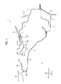
- a vehicle front structure (a structure for a front portion of a vehicle) 1 according to an embodiment of the present invention is applied to a front-engine vehicle, and comprises a dashboard upper member 11, a lid dashboard upper member 12, a windshield lower member 20, and a cowl top member 30.
- the dashboard upper member 11 is a member made of a steel plate, which extends frontward from an upper portion of a dashboard lower member 4 for isolating an engine room 2 from a passenger compartment (vehicle interior) 3.
- the dashboard upper member 11 is secured on the dashboard lower member 4 by welding or the like.
- the lid dashboard upper member 12 is a member made of a steel plate, which extends front-upward from a front end of the dashboard upper member 11.
- the lid dashboard upper member 12 is secured on the dashboard upper member 11 by welding or the like.
- the dashboard upper member 11 and the lid dashboard upper member 12 correspond to the "dashboard upper member" in the claims.
- the reference numeral 8 in FIG. 1 indicates a bonnet hood.
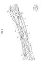
- the windshield lower member 20 is a member made of a steel plate, which supports a lower end portion of a windshield glass 5. As shown in FIG. 1 and FIG.2 , an opening 6 is formed between the lid dashboard upper member 12 and the windshield lower member 20. In the present embodiment, the windshield lower member 20 supports the windshield glass 5 at its one end, and a buffer material 7 is provided between the windshield lower member 20 and the windshield glass 5.
- the windshield lower member 20 which is formed by press molding a sheet of steel plate, comprises a windshield lower member main body 21, and an extended portion 22 that extends frontward from a front end portion 2 1 a of the windshield lower member main body 21.
- the windshield lower member 20 may be formed by press molding a plate made of other metal such as aluminum.
- the windshield lower member main body 21 and the extended portion 22 will later be described in detail with reference to FIG.5 to FIG.7 .
- the cowl top member 30 is a resinous member, which constitutes what is called “cowl box” by covering the opening 6 together with the lid dashboard upper member 12 and the windshield lower member 20.
- the cowl top member 30 comprises an air-intake port 30a of an air-conditioner and a frame number check opening 30b formed near the center in the vehicle width direction, as well as positioning ribs 30c and locking clips 30d as a plurality of locking portions provided at its lower end.
- the frame number check opening 30b is positioned in the obliquely front-upward direction from the extended portion 22 shown in FIG.1 .
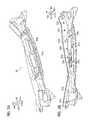
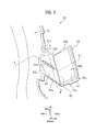
- FIG.5 is a partially enlarged perspective view of the extended portion 22 of the windshield lower member 20 observed from the arrow-X direction shown in FIG.2 .
- FIG.6A is a sectional view across line I-I shown in FIG.5
- FIG.6B is a sectional view across line II-II shown in FIG.5 .
- FIG.7 is a plan view of the lid dashboard upper member 12 and the windshield lower member 20 according to the embodiment of the present invention.
- the windshield lower member main body 21 is a plate-shaped portion molded so as to be bent at a plurality of positions. As shown in FIG.7 , the windshield lower member main body 21 has a left-right asymmetrical shape in plan view, and at its left side end portion 21b there is formed a maximum portion 21d at which width dimension L is largest in the front-rear direction. A plurality of holes 21e, 21e are formed through appropriate positions of the windshield lower member main body 21. On these holes 21e, 21e, the locking clips 30d of the cowl top member 30 are locked (refer to FIG.1 and FIG.3B ).
- the extended portion 22 is a portion on which a chassis number (which is called “frame number”) for identifying each vehicle is incised, and which damps vibration and noise transmitted to the windshield lower member 20.
- the extended portion 22 of the present embodiment is what is called “frame number plate,” and vibration absorption function and noise absorption function are given to this frame number plate.
- the extended portion 22 is molded integrally with the windshield lower member main body 21, and is formed in a bent shape projecting downward by being bent toward the obliquely front-upward direction at a portion substantially center in the front-rear direction.
- the extended portion 22 mainly comprises a base portion 23, a weight portion 24, and a weak portion 25.
- the base portion 23 is a plate-shaped portion which is formed so as to continue from the front end portion 21 a of the windshield lower member main body 21, and which extends obliquely front-downward from the front end portion 21a.
- a stair-like first step 23a which is formed convex upward, is provided in the base portion 23 near the boundary with the front end portion 21 a (portion adjacent to the front end portion 21a).
- a stair-like second step 23b which is formed convex upward, is provided at the right edge of the base portion 23.
- an elongate hole 23c which has a rectangle shape in planar view and extends in the obliquely front-rear direction, is formed so as to penetrate therethrough.
- the hole 23c which is a connecting portion, is locked with a locking clip 30d of the cowl top member 30 (refer to FIG. and FIG.3B ).
- the portions except the first step 23a, the second step 23b and the hole 23c are formed in a flat plane.
- the weight portion 24 is a plate-shaped portion that extends in the obliquely front-upward direction from the front end portion 23d of the base portion 23, and has a function of damping vibration and noise transmitted to the windshield lower member 20 from the engine room 2 by antiphase vibration (oscillation) in the up-down direction (vertical direction).
- flange-shaped protruding portions 24a, 24a are formed so as to extend outward in the vehicle width direction. These protruding portions 24a protrude more outward in the vehicle width direction than the both left and right ends of the base portion 23 and the weak portion 25.
- a third step 24c is formed convex upward.
- a chassis number which is not shown, is incised on the lower surface 24b of the weight portion 24. If checking of the chassis number is needed, an operator can read the chassis number by visually confirming the lower surface 24b of the extended portion 22 through the frame number check opening 30b (refer to FIG.1 ).
- plate thicknesses of the base portion 23 and the weight portion 24 (the extended portion 22) are not limited particularly, but preferably set to 0.6mm for example, and preferably set thinner than the plate thickness of the windshield lower member main body 21.
- angle ⁇ formed between the base portion 23 and the weight portion 24 is preferably set to about 60° for example. This further enhances damping effect by facilitating vibration of the weight portion 24, while also maintaining high visibility for visual confirmation of chassis number through the frame number check opening 30b (refer to FIG.1 ),
- the weak portion 25 is a portion that extends linearly in the vehicle width direction along the boundary between the base portion 23 and the weight portion 24.
- the weak portion 25 is formed by bending the extended portion 22 at its substantially center portion in the front-rear direction toward the obliquely front-upward direction. Because the weak portion 25 does not have a step for increasing its rigidity, the weak portion 25 has lower rigidity relative to the base portion 23 and the weight portion 24 both having steps. Thus, the weak portion 25 becomes a pivot point of vertical vibration of the weight portion 24, as well as a pivot point that is bent when collision load is applied on the weight portion 24 from upward.
- the weight portion 24 which is farthest from the windshield lower member main body 21, vibrates (oscillates) in the up-down direction with respect to the pivot point at the weak portion 25 having lower rigidity than the base portion 23.
- vibration of the weight portion 24 becomes antiphase relative to vibration and noise transmitted to the windshield lower member 20.
- the weight portion 24 can damp vibration and noise transmitted to the windshield lower member 20.
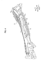
- the cowl top member 30 (refer to FIG.4 ) above the right end portion 21c of the windshield lower member main body 21 (dotted line in FIG.7 )
- the shape of the windshield lower member main body 21 becomes left-right asymmetry, and width dimension in the front-rear direction becomes different between left and right.
- the maximum portion 21d is formed at the left end portion 21b of the windshield lower member main body 21, where width dimension L in the front-rear direction is largest.
- the maximum portion 21 d is a portion that vibrates most sympathetically with vibration and noise transmitted from the engine room 2 (refer to FIG.1 ), and damping effect is enhanced if the extended portion 22 is provided at a position spaced apart from the most sympathetically vibrating part.
- the extended portion 22 of the present embodiment is provided in the area opposite to the maximum portion 21d (on the side of the right end portion 21c) with respect to center line C1 running along the front-rear direction and passing through the center in the vehicle width direction of the windshield lower member main body 21. It is noted that center line C2 running along the front-rear direction and passing through the vehicle width direction of the extended portion 22 is spaced apart from center line C1 outwardly in the vehicle width direction at a predetermined distance, which is set as appropriate.
- the vehicle front structure 1 according to the embodiment of the present invention is basically structured as described above. Next, its action and effect will be explained.
- vibration of the weight portion 24 becomes antiphase relative to vibration and noise transmitted to the windshield lower member 20.
- vibration and noise transmitted to the windshield lower member 20 are damped at the weight portion 24, and transmission of vibration and noise from the engine room 2 into the passenger compartment 3 can be reduced.
- the windshield lower member main body 21 is molded integrally with the extended portion 22, the windshield lower member 20 conventionally provided in a vehicle exercises vibration absorption function and noise absorption function. This makes it unnecessary to provide an insulator separately, and makes it possible to reduce the number of components.
- the windshield lower member main body 21 is molded integrally with the extended portion 22, the number of manufacturing steps can be reduced compared to the prior arts that necessarily include a fixing step for fixing an insulator on the dashboard (for example, the invention described in Patent Document 1).
- the weak portion 25 having lower rigidity than the base portion 23 is provided so as to extend in the vehicle width direction along the boundary between the base portion 23 and the weight portion 24, the extended portion 22 (weight portion 24) becomes susceptible to bending downward with respect to the pivot point at the weak portion 25, and thereby collision energy can be absorbed preferably.
- the base portion 23 since the base portion 23 has the stair-like first step 23 a near the boundary with the front end portion 21a of the windshield lower member main body 21 as well as the stair-like second step 23b on the right edge, rigidity of the base portion 23 increases. Thereby, the weight portion 24 becomes susceptible to vertical vibration of the weight portion 24, and thus damping effect can be further enhanced.
- the base portion 23 is connected with the cowl top member 30 via the hole 23 c, rigidity of the base portion 23 is increased. Thereby, the weight portion 24 becomes susceptible to vertical vibration, and thus damping effect can be further enhanced.
- the weight portion 24 since the weight portion 24 has the protruding portions 24a, 24a protruding outward in the vehicle width direction from the outer ends in the vehicle width direction of the base portion 23 and the weak portion 25, the mass of the weight portion 24 increases. Thereby, the weight portion 24 becomes susceptible to vertical vibration, and thus damping effect can be further enhanced.
- the extended portion 22 is provided on the side opposite to the maximum portion 2 1 d (right end portion 2 1 c) with respect to center line C1 running along the front-rear direction and passing through the center in the vehicle width direction of the windshield lower member main body 21, damping effect can be further enhanced.
- Rigidity of the weak portion 25 of the present embodiment is lower than rigidities of the base portion 23 and the weight portion 24, however, the present invention is not limited thereto, but it is preferably lower than rigidity of the base portion 23 at least.
- the maximum portion 21d of the present embodiment is formed at the left end portion 21b of the windshield lower member main body 21, however, the present invention is not limited thereto, but it may be formed at the right end portion 21c of the windshield lower member main body 21. In this case, the extended portion 22 is provided at the left end portion 21 b.
- the aforementioned dashboard upper member 11 and lid dashboard upper member 12 may be formed integrally out of a sheet of steel plate member, as the dashboard upper member of the present invention.
- the dashboard lower member 4, the dashboard upper member 11 and the lid dashboard upper member 12 may be formed integrally out of a sheet of steel plate member. That is, regardless of whether the dashboard lower member 4, the dashboard upper member 11 and the lid dashboard upper member 12 are formed integrally or separately, the portion extending frontward from the dashboard lower member for isolating the engine room from the passenger compartment corresponds to the dashboard upper member of the present invention.
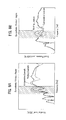
- FIG.8A is a graph in which vertical vibration sensitivity of the working example is compared with vertical vibration sensitivity of the comparative example
- FIG.8B is a graph in which acoustic sensitivity of the working example is compared with acoustic sensitivity of the comparative example
- FIG.9A is a schematic plan view of a vehicle front structure of comparative example which does not constitute the present invention
- FIG.9B is a partially enlarged plan view of FIG.9A .
- FIG.8A and FIG.8B represent frequency [Hz]
- the vertical axis of FIG.8A represents vibration level [dB/N]
- the vertical axis of FIG.8B represents sound pressure level [dB/N].
- the present working example was structured such that the extended portion 22 had the weak portion 25, as in the structure of the aforementioned embodiment. Also, in the present working example, the plate thickness of the extended portion 22 was set thinner than the plate thickness of the windshield lower member main body 21.
- steps for increasing rigidity were formed at both left and right ends of the bent part of the extended portion, providing a structure without a weak portion.
- the plate thickness of the extended portion was set equal to the plate thickness of the windshield lower member main body.
- the aforementioned measurements were performed to obtain the results shown in the graph of FIG.8B with regard to acoustic sensitivities of the working example and the comparative example. That is, comparing the both results, it was confirmed that, in sympathetic vibration region, the sound pressure level [dB/N] of the working example was lower than the sound pressure level [dB/N] of the comparative example (refer to the dotted line in FIG.8B ). Thereby, in the working example, the sound pressure level [dB/N] across sympathetic vibration region falls down, and thus the capability of reducing undesired sound (noise) in the windshield glass was demonstrated.
Landscapes
- Engineering & Computer Science (AREA)
- Chemical & Material Sciences (AREA)
- Combustion & Propulsion (AREA)
- Transportation (AREA)
- Mechanical Engineering (AREA)
- Body Structure For Vehicles (AREA)
- Vehicle Interior And Exterior Ornaments, Soundproofing, And Insulation (AREA)
- Instrument Panels (AREA)
Applications Claiming Priority (2)
| Application Number | Priority Date | Filing Date | Title |
|---|---|---|---|
| JP2011148067 | 2011-07-04 | ||
| PCT/JP2012/066762 WO2013005685A1 (ja) | 2011-07-04 | 2012-06-29 | 車両前部構造 |
Publications (3)
| Publication Number | Publication Date |
|---|---|
| EP2730486A1 true EP2730486A1 (de) | 2014-05-14 |
| EP2730486A4 EP2730486A4 (de) | 2015-02-11 |
| EP2730486B1 EP2730486B1 (de) | 2016-04-27 |
Family
ID=47437037
Family Applications (1)
| Application Number | Title | Priority Date | Filing Date |
|---|---|---|---|
| EP12807669.2A Not-in-force EP2730486B1 (de) | 2011-07-04 | 2012-06-29 | Struktur für die frontpartie eines fahrzeugs |
Country Status (5)
| Country | Link |
|---|---|
| US (1) | US8915539B2 (de) |
| EP (1) | EP2730486B1 (de) |
| JP (1) | JP5747079B2 (de) |
| CN (1) | CN103648891B (de) |
| WO (1) | WO2013005685A1 (de) |
Families Citing this family (6)
| Publication number | Priority date | Publication date | Assignee | Title |
|---|---|---|---|---|
| US9981697B2 (en) * | 2014-04-03 | 2018-05-29 | Toyota Jidosha Kabushiki Kaisha | Cowl structure for a vehicle |
| FR3021286B1 (fr) * | 2014-05-20 | 2016-05-13 | Renault Sa | Ecope pour boite a eau integree a la paroi de separation |
| JP2017001621A (ja) * | 2015-06-15 | 2017-01-05 | トヨタ自動車株式会社 | 車両前部構造 |
| US10308287B2 (en) * | 2017-08-14 | 2019-06-04 | GM Global Technology Operations LLC | Air inlet splash panel assembly for a vehicle |
| CN115195869B (zh) * | 2022-07-20 | 2023-06-06 | 岚图汽车科技有限公司 | 一种前围总成 |
| FR3167079A1 (fr) * | 2024-10-04 | 2026-04-10 | Stellantis Auto Sas | Tablier anti-vibrations pour un véhicule à pare-brise |
Family Cites Families (25)
| Publication number | Priority date | Publication date | Assignee | Title |
|---|---|---|---|---|
| JPS58149866A (ja) | 1982-03-02 | 1983-09-06 | Nissan Motor Co Ltd | 自動車の車体構造 |
| JPS59114167A (ja) * | 1982-12-20 | 1984-07-02 | Mazda Motor Corp | 自動車のダツシユパネルの構造 |
| JPS6347967U (de) * | 1986-09-17 | 1988-03-31 | ||
| JP3144188B2 (ja) * | 1993-11-30 | 2001-03-12 | トヨタ自動車株式会社 | ダッシュパネル構造 |
| JP3640637B2 (ja) * | 2001-12-10 | 2005-04-20 | 本田技研工業株式会社 | 車両用カウルトップパネルのシール構造 |
| JP3610959B2 (ja) * | 2002-03-20 | 2005-01-19 | 日産自動車株式会社 | 車両のカウル構造 |
| JP4040565B2 (ja) * | 2003-10-16 | 2008-01-30 | 本田技研工業株式会社 | カウルボックス部構造 |
| JP4415692B2 (ja) * | 2004-02-13 | 2010-02-17 | 日産自動車株式会社 | 車両のカウル構造 |
| JP4386758B2 (ja) * | 2004-02-25 | 2009-12-16 | 日本プラスト株式会社 | カウルトップカバー |
| JP4207006B2 (ja) * | 2005-01-31 | 2009-01-14 | トヨタ自動車株式会社 | ウインドシールドガラスの支持構造 |
| JP4618090B2 (ja) * | 2005-10-17 | 2011-01-26 | トヨタ自動車株式会社 | ウインドシールドガラス支持構造 |
| JP4490983B2 (ja) * | 2007-03-02 | 2010-06-30 | 本田技研工業株式会社 | 車両のフロントウインドシールド支持構造 |
| JP2008260331A (ja) * | 2007-04-10 | 2008-10-30 | Mazda Motor Corp | 自動車の前部構造 |
| JP5067117B2 (ja) * | 2007-10-25 | 2012-11-07 | マツダ株式会社 | 自動車のカウル構造 |
| JP4492689B2 (ja) * | 2007-12-07 | 2010-06-30 | 日産自動車株式会社 | 自動車のカウル構造 |
| JP5347313B2 (ja) * | 2008-04-18 | 2013-11-20 | スズキ株式会社 | 車両のカウル部構造 |
| JP5394759B2 (ja) * | 2009-01-23 | 2014-01-22 | 日本プラスト株式会社 | カウルトップカバーの取付構造 |
| JP5303737B2 (ja) * | 2009-06-25 | 2013-10-02 | トヨタ車体株式会社 | 自動車におけるカウルルーバ支持構造 |
| GB2486844B (en) * | 2009-09-01 | 2012-10-10 | Nihon Plast Co Ltd | A cowl-top cover |
| JP4924739B2 (ja) * | 2010-05-11 | 2012-04-25 | 日産自動車株式会社 | 自動車の車体構造 |
| JP5459440B2 (ja) * | 2011-02-24 | 2014-04-02 | トヨタ自動車株式会社 | 自動車用カウル部構造 |
| JP5758233B2 (ja) * | 2011-08-31 | 2015-08-05 | マツダ株式会社 | 自動車の前部構造 |
| US8567851B2 (en) * | 2011-09-23 | 2013-10-29 | Nissan North America, Inc. | Vehicle cowl cover |
| US8573682B2 (en) * | 2011-11-04 | 2013-11-05 | Shape Corp. | Vehicle cowl components adapted for hood/fender sealing |
| US8870271B2 (en) * | 2013-03-12 | 2014-10-28 | Honda Motor Co., Ltd. | Vehicle cowl |
-
2012
- 2012-06-29 EP EP12807669.2A patent/EP2730486B1/de not_active Not-in-force
- 2012-06-29 WO PCT/JP2012/066762 patent/WO2013005685A1/ja not_active Ceased
- 2012-06-29 JP JP2013522989A patent/JP5747079B2/ja not_active Expired - Fee Related
- 2012-06-29 CN CN201280033315.5A patent/CN103648891B/zh not_active Expired - Fee Related
- 2012-06-29 US US14/130,641 patent/US8915539B2/en active Active
Non-Patent Citations (2)
| Title |
|---|
| No further relevant documents disclosed * |
| See also references of WO2013005685A1 * |
Also Published As
| Publication number | Publication date |
|---|---|
| CN103648891A (zh) | 2014-03-19 |
| CN103648891B (zh) | 2017-05-17 |
| US8915539B2 (en) | 2014-12-23 |
| EP2730486B1 (de) | 2016-04-27 |
| US20140117720A1 (en) | 2014-05-01 |
| JP5747079B2 (ja) | 2015-07-08 |
| JPWO2013005685A1 (ja) | 2015-02-23 |
| EP2730486A4 (de) | 2015-02-11 |
| WO2013005685A1 (ja) | 2013-01-10 |
Similar Documents
| Publication | Publication Date | Title |
|---|---|---|
| EP2730486B1 (de) | Struktur für die frontpartie eines fahrzeugs | |
| EP2033879B1 (de) | Vorderteilkonstruktion eines Fahrzeuges | |
| CN102862535B (zh) | 车辆用保险杠构造 | |
| KR101405849B1 (ko) | 라디에이터 부시 | |
| JP5201403B2 (ja) | インストルメントパネル構造 | |
| JP6187423B2 (ja) | 自動車のボンネット構造 | |
| JP2015089788A (ja) | 前部車体構造 | |
| KR20230055100A (ko) | 차량의 언더 프로텍터 체결 구조 | |
| JP4816141B2 (ja) | 自動車の前部構造 | |
| CN107010130A (zh) | 备用轮胎支承结构 | |
| KR101272034B1 (ko) | Fem캐리어의 보강구조 | |
| CN222946523U (zh) | 车门结构及车辆 | |
| FR3095796A1 (fr) | Structure avant de véhicule | |
| EP4253200B1 (de) | Fahrzeug und stirnwandoberseite-anordnung dafür | |
| CN222793648U (zh) | 机盖内板组件、机盖总成及车辆 | |
| JP6255962B2 (ja) | カウル部構造 | |
| KR100610973B1 (ko) | 자동차의 트랜스미션 마운팅 구조 | |
| JP4423597B2 (ja) | バンパーの取付構造 | |
| WO2018230204A1 (ja) | 車体前部構造 | |
| KR100578059B1 (ko) | 공조장치의 하부강성증대를 위한 자동차용프론트엔드모듈의 결합구조 | |
| CN108463393A (zh) | 机架的下横梁的加强部件 | |
| JP2006144998A (ja) | ダイナミックダンパ | |
| KR100817216B1 (ko) | 자동차용 냉각기의 설치구조 | |
| JP2003170750A (ja) | ラジエータ取付構造 | |
| WO2022130449A1 (ja) | 車両用ルーフ構造 |
Legal Events
| Date | Code | Title | Description |
|---|---|---|---|
| PUAI | Public reference made under article 153(3) epc to a published international application that has entered the european phase |
Free format text: ORIGINAL CODE: 0009012 |
|
| 17P | Request for examination filed |
Effective date: 20140116 |
|
| AK | Designated contracting states |
Kind code of ref document: A1 Designated state(s): AL AT BE BG CH CY CZ DE DK EE ES FI FR GB GR HR HU IE IS IT LI LT LU LV MC MK MT NL NO PL PT RO RS SE SI SK SM TR |
|
| DAX | Request for extension of the european patent (deleted) | ||
| A4 | Supplementary search report drawn up and despatched |
Effective date: 20150113 |
|
| RIC1 | Information provided on ipc code assigned before grant |
Ipc: B62D 25/08 20060101AFI20150107BHEP |
|
| GRAP | Despatch of communication of intention to grant a patent |
Free format text: ORIGINAL CODE: EPIDOSNIGR1 |
|
| INTG | Intention to grant announced |
Effective date: 20151112 |
|
| GRAS | Grant fee paid |
Free format text: ORIGINAL CODE: EPIDOSNIGR3 |
|
| GRAA | (expected) grant |
Free format text: ORIGINAL CODE: 0009210 |
|
| AK | Designated contracting states |
Kind code of ref document: B1 Designated state(s): AL AT BE BG CH CY CZ DE DK EE ES FI FR GB GR HR HU IE IS IT LI LT LU LV MC MK MT NL NO PL PT RO RS SE SI SK SM TR |
|
| REG | Reference to a national code |
Ref country code: GB Ref legal event code: FG4D |
|
| REG | Reference to a national code |
Ref country code: CH Ref legal event code: EP |
|
| REG | Reference to a national code |
Ref country code: AT Ref legal event code: REF Ref document number: 794432 Country of ref document: AT Kind code of ref document: T Effective date: 20160515 |
|
| REG | Reference to a national code |
Ref country code: IE Ref legal event code: FG4D |
|
| REG | Reference to a national code |
Ref country code: DE Ref legal event code: R096 Ref document number: 602012017862 Country of ref document: DE |
|
| REG | Reference to a national code |
Ref country code: LT Ref legal event code: MG4D |
|
| REG | Reference to a national code |
Ref country code: NL Ref legal event code: MP Effective date: 20160427 |
|
| REG | Reference to a national code |
Ref country code: AT Ref legal event code: MK05 Ref document number: 794432 Country of ref document: AT Kind code of ref document: T Effective date: 20160427 |
|
| PG25 | Lapsed in a contracting state [announced via postgrant information from national office to epo] |
Ref country code: NL Free format text: LAPSE BECAUSE OF FAILURE TO SUBMIT A TRANSLATION OF THE DESCRIPTION OR TO PAY THE FEE WITHIN THE PRESCRIBED TIME-LIMIT Effective date: 20160427 |
|
| PG25 | Lapsed in a contracting state [announced via postgrant information from national office to epo] |
Ref country code: NO Free format text: LAPSE BECAUSE OF FAILURE TO SUBMIT A TRANSLATION OF THE DESCRIPTION OR TO PAY THE FEE WITHIN THE PRESCRIBED TIME-LIMIT Effective date: 20160727 Ref country code: PL Free format text: LAPSE BECAUSE OF FAILURE TO SUBMIT A TRANSLATION OF THE DESCRIPTION OR TO PAY THE FEE WITHIN THE PRESCRIBED TIME-LIMIT Effective date: 20160427 Ref country code: FI Free format text: LAPSE BECAUSE OF FAILURE TO SUBMIT A TRANSLATION OF THE DESCRIPTION OR TO PAY THE FEE WITHIN THE PRESCRIBED TIME-LIMIT Effective date: 20160427 Ref country code: LT Free format text: LAPSE BECAUSE OF FAILURE TO SUBMIT A TRANSLATION OF THE DESCRIPTION OR TO PAY THE FEE WITHIN THE PRESCRIBED TIME-LIMIT Effective date: 20160427 |
|
| PG25 | Lapsed in a contracting state [announced via postgrant information from national office to epo] |
Ref country code: AT Free format text: LAPSE BECAUSE OF FAILURE TO SUBMIT A TRANSLATION OF THE DESCRIPTION OR TO PAY THE FEE WITHIN THE PRESCRIBED TIME-LIMIT Effective date: 20160427 Ref country code: SE Free format text: LAPSE BECAUSE OF FAILURE TO SUBMIT A TRANSLATION OF THE DESCRIPTION OR TO PAY THE FEE WITHIN THE PRESCRIBED TIME-LIMIT Effective date: 20160427 Ref country code: LV Free format text: LAPSE BECAUSE OF FAILURE TO SUBMIT A TRANSLATION OF THE DESCRIPTION OR TO PAY THE FEE WITHIN THE PRESCRIBED TIME-LIMIT Effective date: 20160427 Ref country code: RS Free format text: LAPSE BECAUSE OF FAILURE TO SUBMIT A TRANSLATION OF THE DESCRIPTION OR TO PAY THE FEE WITHIN THE PRESCRIBED TIME-LIMIT Effective date: 20160427 Ref country code: PT Free format text: LAPSE BECAUSE OF FAILURE TO SUBMIT A TRANSLATION OF THE DESCRIPTION OR TO PAY THE FEE WITHIN THE PRESCRIBED TIME-LIMIT Effective date: 20160829 Ref country code: HR Free format text: LAPSE BECAUSE OF FAILURE TO SUBMIT A TRANSLATION OF THE DESCRIPTION OR TO PAY THE FEE WITHIN THE PRESCRIBED TIME-LIMIT Effective date: 20160427 Ref country code: GR Free format text: LAPSE BECAUSE OF FAILURE TO SUBMIT A TRANSLATION OF THE DESCRIPTION OR TO PAY THE FEE WITHIN THE PRESCRIBED TIME-LIMIT Effective date: 20160728 Ref country code: ES Free format text: LAPSE BECAUSE OF FAILURE TO SUBMIT A TRANSLATION OF THE DESCRIPTION OR TO PAY THE FEE WITHIN THE PRESCRIBED TIME-LIMIT Effective date: 20160427 |
|
| PG25 | Lapsed in a contracting state [announced via postgrant information from national office to epo] |
Ref country code: IT Free format text: LAPSE BECAUSE OF FAILURE TO SUBMIT A TRANSLATION OF THE DESCRIPTION OR TO PAY THE FEE WITHIN THE PRESCRIBED TIME-LIMIT Effective date: 20160427 Ref country code: BE Free format text: LAPSE BECAUSE OF FAILURE TO SUBMIT A TRANSLATION OF THE DESCRIPTION OR TO PAY THE FEE WITHIN THE PRESCRIBED TIME-LIMIT Effective date: 20160427 |
|
| REG | Reference to a national code |
Ref country code: DE Ref legal event code: R097 Ref document number: 602012017862 Country of ref document: DE |
|
| PG25 | Lapsed in a contracting state [announced via postgrant information from national office to epo] |
Ref country code: RO Free format text: LAPSE BECAUSE OF FAILURE TO SUBMIT A TRANSLATION OF THE DESCRIPTION OR TO PAY THE FEE WITHIN THE PRESCRIBED TIME-LIMIT Effective date: 20160427 Ref country code: MC Free format text: LAPSE BECAUSE OF FAILURE TO SUBMIT A TRANSLATION OF THE DESCRIPTION OR TO PAY THE FEE WITHIN THE PRESCRIBED TIME-LIMIT Effective date: 20160427 Ref country code: DK Free format text: LAPSE BECAUSE OF FAILURE TO SUBMIT A TRANSLATION OF THE DESCRIPTION OR TO PAY THE FEE WITHIN THE PRESCRIBED TIME-LIMIT Effective date: 20160427 Ref country code: CZ Free format text: LAPSE BECAUSE OF FAILURE TO SUBMIT A TRANSLATION OF THE DESCRIPTION OR TO PAY THE FEE WITHIN THE PRESCRIBED TIME-LIMIT Effective date: 20160427 Ref country code: EE Free format text: LAPSE BECAUSE OF FAILURE TO SUBMIT A TRANSLATION OF THE DESCRIPTION OR TO PAY THE FEE WITHIN THE PRESCRIBED TIME-LIMIT Effective date: 20160427 Ref country code: SK Free format text: LAPSE BECAUSE OF FAILURE TO SUBMIT A TRANSLATION OF THE DESCRIPTION OR TO PAY THE FEE WITHIN THE PRESCRIBED TIME-LIMIT Effective date: 20160427 |
|
| REG | Reference to a national code |
Ref country code: CH Ref legal event code: PL |
|
| PG25 | Lapsed in a contracting state [announced via postgrant information from national office to epo] |
Ref country code: SM Free format text: LAPSE BECAUSE OF FAILURE TO SUBMIT A TRANSLATION OF THE DESCRIPTION OR TO PAY THE FEE WITHIN THE PRESCRIBED TIME-LIMIT Effective date: 20160427 |
|
| PLBE | No opposition filed within time limit |
Free format text: ORIGINAL CODE: 0009261 |
|
| STAA | Information on the status of an ep patent application or granted ep patent |
Free format text: STATUS: NO OPPOSITION FILED WITHIN TIME LIMIT |
|
| REG | Reference to a national code |
Ref country code: IE Ref legal event code: MM4A |
|
| REG | Reference to a national code |
Ref country code: FR Ref legal event code: ST Effective date: 20170228 |
|
| 26N | No opposition filed |
Effective date: 20170130 |
|
| PG25 | Lapsed in a contracting state [announced via postgrant information from national office to epo] |
Ref country code: FR Free format text: LAPSE BECAUSE OF NON-PAYMENT OF DUE FEES Effective date: 20160630 Ref country code: LI Free format text: LAPSE BECAUSE OF NON-PAYMENT OF DUE FEES Effective date: 20160630 Ref country code: CH Free format text: LAPSE BECAUSE OF NON-PAYMENT OF DUE FEES Effective date: 20160630 |
|
| PG25 | Lapsed in a contracting state [announced via postgrant information from national office to epo] |
Ref country code: IE Free format text: LAPSE BECAUSE OF NON-PAYMENT OF DUE FEES Effective date: 20160629 Ref country code: SI Free format text: LAPSE BECAUSE OF FAILURE TO SUBMIT A TRANSLATION OF THE DESCRIPTION OR TO PAY THE FEE WITHIN THE PRESCRIBED TIME-LIMIT Effective date: 20160427 |
|
| PGFP | Annual fee paid to national office [announced via postgrant information from national office to epo] |
Ref country code: GB Payment date: 20170620 Year of fee payment: 6 Ref country code: DE Payment date: 20170531 Year of fee payment: 6 |
|
| PG25 | Lapsed in a contracting state [announced via postgrant information from national office to epo] |
Ref country code: HU Free format text: LAPSE BECAUSE OF FAILURE TO SUBMIT A TRANSLATION OF THE DESCRIPTION OR TO PAY THE FEE WITHIN THE PRESCRIBED TIME-LIMIT; INVALID AB INITIO Effective date: 20120629 |
|
| PG25 | Lapsed in a contracting state [announced via postgrant information from national office to epo] |
Ref country code: MK Free format text: LAPSE BECAUSE OF FAILURE TO SUBMIT A TRANSLATION OF THE DESCRIPTION OR TO PAY THE FEE WITHIN THE PRESCRIBED TIME-LIMIT Effective date: 20160427 Ref country code: IS Free format text: LAPSE BECAUSE OF FAILURE TO SUBMIT A TRANSLATION OF THE DESCRIPTION OR TO PAY THE FEE WITHIN THE PRESCRIBED TIME-LIMIT Effective date: 20160427 Ref country code: LU Free format text: LAPSE BECAUSE OF NON-PAYMENT OF DUE FEES Effective date: 20160629 Ref country code: CY Free format text: LAPSE BECAUSE OF FAILURE TO SUBMIT A TRANSLATION OF THE DESCRIPTION OR TO PAY THE FEE WITHIN THE PRESCRIBED TIME-LIMIT Effective date: 20160427 Ref country code: MT Free format text: LAPSE BECAUSE OF NON-PAYMENT OF DUE FEES Effective date: 20160630 |
|
| PG25 | Lapsed in a contracting state [announced via postgrant information from national office to epo] |
Ref country code: BG Free format text: LAPSE BECAUSE OF FAILURE TO SUBMIT A TRANSLATION OF THE DESCRIPTION OR TO PAY THE FEE WITHIN THE PRESCRIBED TIME-LIMIT Effective date: 20160427 |
|
| PG25 | Lapsed in a contracting state [announced via postgrant information from national office to epo] |
Ref country code: TR Free format text: LAPSE BECAUSE OF FAILURE TO SUBMIT A TRANSLATION OF THE DESCRIPTION OR TO PAY THE FEE WITHIN THE PRESCRIBED TIME-LIMIT Effective date: 20160427 Ref country code: AL Free format text: LAPSE BECAUSE OF FAILURE TO SUBMIT A TRANSLATION OF THE DESCRIPTION OR TO PAY THE FEE WITHIN THE PRESCRIBED TIME-LIMIT Effective date: 20160427 |
|
| REG | Reference to a national code |
Ref country code: DE Ref legal event code: R119 Ref document number: 602012017862 Country of ref document: DE |
|
| GBPC | Gb: european patent ceased through non-payment of renewal fee |
Effective date: 20180629 |
|
| PG25 | Lapsed in a contracting state [announced via postgrant information from national office to epo] |
Ref country code: GB Free format text: LAPSE BECAUSE OF NON-PAYMENT OF DUE FEES Effective date: 20180629 Ref country code: DE Free format text: LAPSE BECAUSE OF NON-PAYMENT OF DUE FEES Effective date: 20190101 |