EP2730686A1 - Rotor de filage à extrémité ouverte - Google Patents
Rotor de filage à extrémité ouverte Download PDFInfo
- Publication number
- EP2730686A1 EP2730686A1 EP13004898.6A EP13004898A EP2730686A1 EP 2730686 A1 EP2730686 A1 EP 2730686A1 EP 13004898 A EP13004898 A EP 13004898A EP 2730686 A1 EP2730686 A1 EP 2730686A1
- Authority
- EP
- European Patent Office
- Prior art keywords
- rotor
- cylindrical bore
- open
- end spinning
- cup
- Prior art date
- Legal status (The legal status is an assumption and is not a legal conclusion. Google has not performed a legal analysis and makes no representation as to the accuracy of the status listed.)
- Granted
Links
Images


Classifications
-
- D—TEXTILES; PAPER
- D01—NATURAL OR MAN-MADE THREADS OR FIBRES; SPINNING
- D01H—SPINNING OR TWISTING
- D01H4/00—Open-end spinning machines or arrangements for imparting twist to independently moving fibres separated from slivers; Piecing arrangements therefor; Covering endless core threads with fibres by open-end spinning techniques
- D01H4/04—Open-end spinning machines or arrangements for imparting twist to independently moving fibres separated from slivers; Piecing arrangements therefor; Covering endless core threads with fibres by open-end spinning techniques imparting twist by contact of fibres with a running surface
- D01H4/08—Rotor spinning, i.e. the running surface being provided by a rotor
- D01H4/10—Rotors
Definitions
- the invention relates to an open-end spinning rotor comprising a rotor shaft, a rotor cup and a coupling device which releasably connects the rotor shaft and the rotor cup.
- the coupling device has locking means for axially locking the rotor cup, transmission means for the positive transmission of torque from the rotor shaft to the rotor cup, and additionally centering means for centering the rotor shaft and the rotor cup.
- the centering means comprise a cylindrical bore and a corresponding guide lug, which is insertable into the cylindrical bore.
- Spinning rotors used in open-end rotor spinning machines must be interchangeable as needed, for example when worn or to produce another type of yarn on the rotor spinning machine. Depending on the type of storage, it may make the change of open-end spinning rotors difficult or even impossible if the rotor cup and the rotor shaft are permanently connected to each other. Therefore, a number of considerations have already been made as to how the connection between rotor cup and rotor shaft can be made detachable. In addition to the simple interchangeability of the rotor cup is the safe connection during operation of the spinning rotor in the foreground. It should be noted that the spinning rotor is operated at speeds of 150,000 revolutions per minute and more. There are known rotor spinning machines, which reach up to 200,000 revolutions per minute.
- the cylindrical bore should enclose the guide lug without play.
- a backlash-free connection is not possible due to the ever-present manufacturing tolerances.
- a game between the cylindrical bore and the guide lug will always be necessary.
- imbalance forces that can damage the drive and / or the bearing of the spinning rotor can arise at the high rotational speeds with which the spinning rotor rotates.
- the unbalance is caused by the misalignment between rotor cup and rotor shaft.
- the DE 10 2009 048 295 A1 also discloses a spinning rotor having a rotor cup and a rotor shaft. These are detachably connected to each other.
- the rotor shaft has a bore and the rotor cup a stub shaft, which is insertable into the bore.
- a spring element is arranged to be tensioned during insertion of the stub shaft into the bore so that a torque is transmitted from the rotor shaft to the rotor cup.
- a non-positive torque transmission does not have the required reliability. To imbalance forces makes the Scripture no statement.
- the EP 0 808 923 A1 discloses an open-end spinning rotor, consisting of a rotor cup and a receiving this receiving part over which the rotor cup is stored and driven. Rotortasse and carrier part are connected by a clip connection. A part of the clip connection is received via an elastic element. As a result, the necessary deformability of the clip connection for assembly is achieved.
- the elastic element is also intended to damp vibrations generated by an unbalance of the rotor mass. An axial offset of rotor cup and carrier part or rotor shaft can not be prevented by the disclosed construction.
- the DE 38 15 182 A1 discloses various coupling devices for releasably connecting rotor shaft and rotor cup. It is proposed, inter alia, consisting of an elastic material centering, which is mounted between an attached to the rotor cup coupling pin and connected to the rotor shaft coupling shell.
- the diameter of the coupling pin is significantly smaller than the diameter of the coupling shell.
- the space between pin and shell is filled exclusively by the elastic centering. It is doubtful that the centering accuracy required for modern rotor spinning machines can be achieved in this way
- the spinning rotor of EP 1 156 142 B1 develop so that the rotor cup can be easily replaced and at the same time a reliable centering of rotor cup and rotor shaft is achieved.
- the cylindrical bore and the guide lug on a clearance fit and the centering means comprise a resilient arrangement which is located between the cylindrical bore and the guide lug.
- the clearance between the cylindrical bore and the guide lug is less than 0.1mm. In this area, one can assume that the centering can be reliably enabled by means of the elastic arrangement.
- the centering is improved the less the clearance between the bore and guide approach.
- the production cost increases the tighter the chosen tolerances are.
- the tolerances are chosen so that the clearance between the cylindrical bore and the guide lug is less than 0.01 mm. Such tolerances can be produced realistically and the centering by the elastic arrangement is optimal.
- the extent of the elastic arrangement in the axial direction of the cylindrical bore is greater than 0.8 times the diameter of the cylindrical bore.
- the manufacturing accuracy of the elastic arrangement is limited. This is especially true when the elastic assembly is integrally formed and has a greater length. Therefore, advantageously, the extension of the elastic assembly in the axial direction of the cylindrical bore is less than 2.4 times the diameter of the cylindrical bore.
- the elastic assembly comprises an elastic member. It is possible to use only a single elastic element. That is, the elastic assembly is integrally formed.
- the elastic arrangement comprises a second elastic element, which is arranged in the axial direction of the cylindrical bore spaced from the first elastic element.
- the elastic element may be formed, for example, as a tolerance sleeve.
- the tolerance sleeve may be formed as a corrugated band and consist of spring band steel.
- the elastic element may also be formed as an O-ring.
- O-rings are used axially spaced from each other.
- two tolerance sleeves it is also possible to use two tolerance sleeves in this way.
- the centering can be improved if in the cylindrical bore or the guide lug there is a circumferential recess in which the elastic element is inserted.
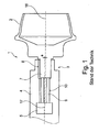
- the Fig. 1 and the Fig. 2 show a spinning rotor 1 with a coupling device 3 as in the prior art, for example, from the above-cited EP 1 156 142 B1 known.
- the two figures are intended to explain the problems which are overcome by the present invention.
- the FIGS. 1 and 2 Both show the same spinning rotor 1, so that this will be described only once.
- the spinning rotor 1 comprises a rotor cup 2 and a rotor shaft 4, which are connected to one another via a coupling device 3.
- the rotor shaft 4 is mounted in a suitable, not shown storage and connected to a drive, not shown.
- the drive sets the rotor shaft 4 and thus the spinning rotor 1 in rotation.
- the rotor cup 2 has an approach.
- the approach is divided into a cylindrical guide projection 7 and a positive locking element 9.
- the positive-locking element 9 is formed as an external polygon.
- the rotor shaft 4 has a cylindrical bore 8, which corresponds to the cylindrical guide projection 7.
- the rotor shaft 4 has a form-locking element 10 which is designed as an internal polygon and which corresponds with the form-fitting element 9.
- the interlocking elements 9 and 10 create a positive connection between the rotor cup 2 and the rotor shaft 4, so that a torque can be transmitted.
- the rotor shaft 4 has a magnet 5, which adjoins the polygonal socket on. The magnet 5 exerts an attraction on the ferromagnetic approach of the rotor cup 2.
- the magnetic attraction forces are sufficient.
- Fig. 1 are also the axes 16 and 17 located.
- the axis 16 is the axis of symmetry of the rotor cup 2.
- the axis 17 illustrates the axis of symmetry of the rotor shaft 4. Due to the clearance between the cylindrical bore 8 and the guide projection 7, the axes on an offset e. This offset e leads to an imbalance of the spinning rotor. This imbalance can be up to 200,000 min -1 lead to damage of the bearing or of the drive at rotational speeds.
- the axes are offset parallel to each other.
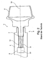
- Fig. 2 shows the same spinning rotor 1 as Fig.
- the axes 16 and 17 are not offset from each other in parallel, but rotor shaft 4 and rotor cup 2 are tilted against each other.
- the axes 16 and 17 of rotor cup 2 and rotor shaft 4 have an angular offset.
- the angular offset also arises due to the clearance between the rotor shaft 4 and rotor cup 2 and leads to an imbalance of the system with the disadvantages described above.
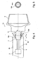
- the Fig. 3 shows a spinning rotor 1a according to the invention.
- the rotor cup 2 with the rotor cup 2 of FIGS. 1 and 2 identical.
- the rotor shaft 4a has, corresponding to the rotor shaft 4, a cylindrical bore 8, an internal polygon 10 and a magnet 5 for the axial locking of the rotor cup 2.
- the coupling device 3a of the spinning rotor 1a still differs from the coupling device 3 of the spinning rotor 1.
- two O-rings 13 and 14 are additionally arranged.
- two recesses 18 and 19 are provided, in which the O-rings 13 and 14 are inserted.
- the two O-rings form an elastic arrangement.
- the extent of the elastic arrangement in the axial direction of the cylindrical bore is in Fig. 3 denoted by l a .
- the diameter of the cylindrical bore 8 is denoted by d. If the extent l a in relation to the diameter d is sufficiently large, an angular offset between the axes of the rotor cup 2 and the rotor shaft 4 a can be prevented.
- the extent l a must be at least 80% of the diameter d.
- FIGS. 4 and 5 show an alternative embodiment of the present invention.
- the difference between the spinning rotor 1b and the spinning rotor 1a lies in the fact that the coupling device 3b has a different elastic arrangement.
- the rotor shaft 4b has on the circumference of the cylindrical bore 8 a recess 20b.
- a tolerance sleeve 15b is applied.
- Fig. 5 a section through the tolerance sleeve along the section line AA.
- the Fig. 5 shows that the tolerance sleeve 15b is formed as a corrugated band.
- the corrugated band can be made of spring band steel.
- the elastic arrangement consists of the elastic element, namely the tolerance sleeve 15b.
- the length l b of the tolerance sleeve 15b corresponds to the extent of the elastic arrangement in the axial direction of the cylindrical bore.
- the length l b is also chosen here in relation to the diameter d of the cylindrical bore 8 so that an angular offset is avoided.
- the spinning rotor 1c includes a rotor cup 2c, a clutch device 3c and a rotor shaft 4c.
- the rotor shaft 4 does not have a cylindrical bore 8, but the rotor cup 2c has a cylindrical bore 8c.
- the rotor shaft 4c has a guide lug 7c corresponding thereto. In the guide projection 7c, a circumferential recess 20c is introduced.
- the tolerance sleeve 15c can be arranged to center the rotor cup 2c and rotor shaft 4c.
- the rotor shaft 4c has a positive-locking element 11.
- the rotor cup 2c comprises a form-fitting element 12 corresponding thereto
- Fig. 7 shows the section BB with the two form-fitting elements 11 and 12.
- the positive-locking elements 11 and 12 have a circular cylindrical shape with two flat surfaces on the circumference. Other shapes are possible.
Landscapes
- Engineering & Computer Science (AREA)
- Mechanical Engineering (AREA)
- Textile Engineering (AREA)
- Spinning Or Twisting Of Yarns (AREA)
Applications Claiming Priority (1)
| Application Number | Priority Date | Filing Date | Title |
|---|---|---|---|
| DE102012022092.8A DE102012022092A1 (de) | 2012-11-10 | 2012-11-10 | Offenend-Spinnrotor |
Related Parent Applications (1)
| Application Number | Title | Priority Date | Filing Date |
|---|---|---|---|
| DE102012022092 Previously-Filed-Application | 2012-11-10 |
Publications (2)
| Publication Number | Publication Date |
|---|---|
| EP2730686A1 true EP2730686A1 (fr) | 2014-05-14 |
| EP2730686B1 EP2730686B1 (fr) | 2015-12-16 |
Family
ID=49474182
Family Applications (1)
| Application Number | Title | Priority Date | Filing Date |
|---|---|---|---|
| EP13004898.6A Revoked EP2730686B1 (fr) | 2012-11-10 | 2013-10-11 | Rotor de filage à extrémité ouverte |
Country Status (4)
| Country | Link |
|---|---|
| EP (1) | EP2730686B1 (fr) |
| CN (1) | CN103806144B (fr) |
| DE (1) | DE102012022092A1 (fr) |
| IN (1) | IN2013MU03291A (fr) |
Cited By (4)
| Publication number | Priority date | Publication date | Assignee | Title |
|---|---|---|---|---|
| CN108085801A (zh) * | 2016-11-23 | 2018-05-29 | 里特机械公司 | 转子托盘和带有转子托盘的自由端纺纱转子 |
| EP3498895A1 (fr) * | 2017-12-07 | 2019-06-19 | Maschinenfabrik Rieter AG | Cylindre ouvreur d'un dispositif de filage à bout libre ainsi que dispositif de filage à bout libre |
| CN110424073A (zh) * | 2019-08-10 | 2019-11-08 | 苏州当峰纺织有限公司 | 一种用于气流纺纱机上的纺纱装置 |
| EP4530381A1 (fr) * | 2023-09-28 | 2025-04-02 | PhiComp AG | Coupelle de rotor pour filature |
Families Citing this family (1)
| Publication number | Priority date | Publication date | Assignee | Title |
|---|---|---|---|---|
| DE102016123698A1 (de) * | 2016-12-07 | 2018-06-07 | Saurer Germany Gmbh & Co. Kg | Spinnrotor für eine Offenend-Spinnvorrichtung und Offenend- Spinnvorrichtung |
Citations (7)
| Publication number | Priority date | Publication date | Assignee | Title |
|---|---|---|---|---|
| DE2540106A1 (de) * | 1975-09-09 | 1977-03-17 | Teldix Gmbh | Anordnung mit schnelldrehendem rotor |
| DE3815182A1 (de) | 1988-05-04 | 1989-11-16 | Wolfgang Grahamer | Spinnrotor |
| EP0805224A2 (fr) * | 1996-05-04 | 1997-11-05 | Rieter Ingolstadt Spinnereimaschinenbau AG | Rotor de filage à bout libre |
| EP0808923A1 (fr) | 1996-05-25 | 1997-11-26 | Rieter Ingolstadt Spinnereimaschinenbau AG | Rotor de filage à bout libre |
| EP1156142B1 (fr) | 2000-05-16 | 2004-04-21 | Saurer GmbH & Co. KG | Rotor de filage à bout libre |
| DE102009048295A1 (de) | 2009-10-05 | 2010-07-29 | Oerlikon Textile Gmbh & Co. Kg | Offenend-Spinnrotor |
| DE102012008693A1 (de) | 2012-04-28 | 2013-10-31 | Oerlikon Textile Gmbh & Co. Kg | Offenend-Spinnrotor |
Family Cites Families (3)
| Publication number | Priority date | Publication date | Assignee | Title |
|---|---|---|---|---|
| DE2822108A1 (de) | 1978-05-20 | 1979-11-29 | Kugelfischer G Schaefer & Co | Elastische lagerung |
| DE19734637A1 (de) | 1996-12-20 | 1998-06-25 | Schlafhorst & Co W | Axiallager für einen Offenend-Spinnrotor |
| DE102005062196A1 (de) * | 2005-12-23 | 2007-06-28 | Saurer Gmbh & Co. Kg | Offenend-Spinnrotor für eine Kreuzspulen herstellende Textilmaschine |
-
2012
- 2012-11-10 DE DE102012022092.8A patent/DE102012022092A1/de not_active Withdrawn
-
2013
- 2013-10-11 EP EP13004898.6A patent/EP2730686B1/fr not_active Revoked
- 2013-10-21 IN IN3291MU2013 patent/IN2013MU03291A/en unknown
- 2013-11-05 CN CN201310541295.9A patent/CN103806144B/zh not_active Expired - Fee Related
Patent Citations (7)
| Publication number | Priority date | Publication date | Assignee | Title |
|---|---|---|---|---|
| DE2540106A1 (de) * | 1975-09-09 | 1977-03-17 | Teldix Gmbh | Anordnung mit schnelldrehendem rotor |
| DE3815182A1 (de) | 1988-05-04 | 1989-11-16 | Wolfgang Grahamer | Spinnrotor |
| EP0805224A2 (fr) * | 1996-05-04 | 1997-11-05 | Rieter Ingolstadt Spinnereimaschinenbau AG | Rotor de filage à bout libre |
| EP0808923A1 (fr) | 1996-05-25 | 1997-11-26 | Rieter Ingolstadt Spinnereimaschinenbau AG | Rotor de filage à bout libre |
| EP1156142B1 (fr) | 2000-05-16 | 2004-04-21 | Saurer GmbH & Co. KG | Rotor de filage à bout libre |
| DE102009048295A1 (de) | 2009-10-05 | 2010-07-29 | Oerlikon Textile Gmbh & Co. Kg | Offenend-Spinnrotor |
| DE102012008693A1 (de) | 2012-04-28 | 2013-10-31 | Oerlikon Textile Gmbh & Co. Kg | Offenend-Spinnrotor |
Cited By (5)
| Publication number | Priority date | Publication date | Assignee | Title |
|---|---|---|---|---|
| CN108085801A (zh) * | 2016-11-23 | 2018-05-29 | 里特机械公司 | 转子托盘和带有转子托盘的自由端纺纱转子 |
| EP3498895A1 (fr) * | 2017-12-07 | 2019-06-19 | Maschinenfabrik Rieter AG | Cylindre ouvreur d'un dispositif de filage à bout libre ainsi que dispositif de filage à bout libre |
| US10822726B2 (en) | 2017-12-07 | 2020-11-03 | Maschinenfabrik Rieter Ag | Opening roller for an open-end spinning device, and open-end spinning device with the opening roller |
| CN110424073A (zh) * | 2019-08-10 | 2019-11-08 | 苏州当峰纺织有限公司 | 一种用于气流纺纱机上的纺纱装置 |
| EP4530381A1 (fr) * | 2023-09-28 | 2025-04-02 | PhiComp AG | Coupelle de rotor pour filature |
Also Published As
| Publication number | Publication date |
|---|---|
| DE102012022092A1 (de) | 2014-05-15 |
| IN2013MU03291A (fr) | 2015-07-10 |
| CN103806144A (zh) | 2014-05-21 |
| CN103806144B (zh) | 2017-04-26 |
| EP2730686B1 (fr) | 2015-12-16 |
Similar Documents
| Publication | Publication Date | Title |
|---|---|---|
| EP2730686B1 (fr) | Rotor de filage à extrémité ouverte | |
| DE69206872T2 (de) | Magnetische Antriebsvorrichtung | |
| DE3047606C2 (de) | Lageranordnung für einen länglichen, um seine Längsachse drehbaren Drehkörper | |
| DE3044415A1 (de) | Elastische kupplung zum uebertragen einer drehbewegung | |
| WO2014108111A2 (fr) | Rotor pour un arbre d'une machine électrique à flux axial | |
| DE102018212459B4 (de) | Sensormagnet und motor | |
| EP3884197B1 (fr) | Accouplement | |
| EP3327187A1 (fr) | Cloche de rotor et rotor pour métier à filer à bout libre doté d'une cloche de rotor | |
| DE102010054510B4 (de) | Wellenkupplung | |
| EP3570084B1 (fr) | Dispositif de transmission de signaux optiques entre deux unités structurales rotatives | |
| EP3153611A1 (fr) | Cloche de rotor de filature à bout libre comprenant un dispositif d'accouplement | |
| DE2422639C2 (de) | Elastische Kupplung | |
| EP2907903B1 (fr) | Rotor pour métiers à filer à bout libre | |
| DE2934710C2 (de) | Rotor zur Drehenergiespeicherung | |
| DE3916315A1 (de) | Schaftwerkzeug | |
| DE102015215907A1 (de) | Fliehkraftpendel | |
| EP0515006A1 (fr) | Elément d'assemblage d'une tige à la périphérie d'un corps de rotation | |
| DE4332142C1 (de) | Schlingfederkupplung für zwei fluchtende Wellen | |
| DE102015101387B3 (de) | Optische Fassung mit wenigstens einer Klemmeinheit mit einer Membranfeder | |
| EP3023523B1 (fr) | Broche pour dispositif de fausse torsion et dispositif de fausse torsion | |
| DE102018004534A1 (de) | Verbindung, aufweisend eine in eine Hohlwelle zumindest teilweise eingesteckte Welle und ein auf die Hohlwelle aufgestecktes Ringteil und Planetengetriebe | |
| DE3409759A1 (de) | Verfahren zum ausgleich der rotationsgeschwindigkeit zweier koaxialer drehbarer teile, geschwindigkeitsausgleichvorrichtung sowie diese aufweisende waschmaschine | |
| DE4103931A1 (de) | Stabilisierungs- und abstuetzeinrichtung fuer die schwenklagerung eines kupplungshebels | |
| DE2524373C2 (de) | Vorrichtung zum Kuppeln eines einem Rotationsverdampfer zugehörenden Dampfdurchführungsrohres mit einem angetriebenen Mitnehmerrohr | |
| DE102018004535A1 (de) | Verbindung, aufweisend eine in eine Hohlwelle zumindest teilweise eingesteckte Welle und ein auf die Hohlwelle aufgestecktes Ringteil und Planetengetriebe |
Legal Events
| Date | Code | Title | Description |
|---|---|---|---|
| PUAI | Public reference made under article 153(3) epc to a published international application that has entered the european phase |
Free format text: ORIGINAL CODE: 0009012 |
|
| 17P | Request for examination filed |
Effective date: 20131011 |
|
| AK | Designated contracting states |
Kind code of ref document: A1 Designated state(s): AL AT BE BG CH CY CZ DE DK EE ES FI FR GB GR HR HU IE IS IT LI LT LU LV MC MK MT NL NO PL PT RO RS SE SI SK SM TR |
|
| AX | Request for extension of the european patent |
Extension state: BA ME |
|
| R17P | Request for examination filed (corrected) |
Effective date: 20141114 |
|
| RBV | Designated contracting states (corrected) |
Designated state(s): AL AT BE BG CH CY CZ DE DK EE ES FI FR GB GR HR HU IE IS IT LI LT LU LV MC MK MT NL NO PL PT RO RS SE SI SK SM TR |
|
| GRAP | Despatch of communication of intention to grant a patent |
Free format text: ORIGINAL CODE: EPIDOSNIGR1 |
|
| INTG | Intention to grant announced |
Effective date: 20150716 |
|
| GRAS | Grant fee paid |
Free format text: ORIGINAL CODE: EPIDOSNIGR3 |
|
| GRAA | (expected) grant |
Free format text: ORIGINAL CODE: 0009210 |
|
| AK | Designated contracting states |
Kind code of ref document: B1 Designated state(s): AL AT BE BG CH CY CZ DE DK EE ES FI FR GB GR HR HU IE IS IT LI LT LU LV MC MK MT NL NO PL PT RO RS SE SI SK SM TR |
|
| REG | Reference to a national code |
Ref country code: GB Ref legal event code: FG4D Free format text: NOT ENGLISH |
|
| REG | Reference to a national code |
Ref country code: CH Ref legal event code: EP |
|
| REG | Reference to a national code |
Ref country code: IE Ref legal event code: FG4D Free format text: LANGUAGE OF EP DOCUMENT: GERMAN |
|
| REG | Reference to a national code |
Ref country code: AT Ref legal event code: REF Ref document number: 765609 Country of ref document: AT Kind code of ref document: T Effective date: 20160115 |
|
| REG | Reference to a national code |
Ref country code: DE Ref legal event code: R096 Ref document number: 502013001628 Country of ref document: DE |
|
| REG | Reference to a national code |
Ref country code: NL Ref legal event code: MP Effective date: 20151216 |
|
| REG | Reference to a national code |
Ref country code: LT Ref legal event code: MG4D |
|
| PG25 | Lapsed in a contracting state [announced via postgrant information from national office to epo] |
Ref country code: NO Free format text: LAPSE BECAUSE OF FAILURE TO SUBMIT A TRANSLATION OF THE DESCRIPTION OR TO PAY THE FEE WITHIN THE PRESCRIBED TIME-LIMIT Effective date: 20160316 Ref country code: HR Free format text: LAPSE BECAUSE OF FAILURE TO SUBMIT A TRANSLATION OF THE DESCRIPTION OR TO PAY THE FEE WITHIN THE PRESCRIBED TIME-LIMIT Effective date: 20151216 Ref country code: LT Free format text: LAPSE BECAUSE OF FAILURE TO SUBMIT A TRANSLATION OF THE DESCRIPTION OR TO PAY THE FEE WITHIN THE PRESCRIBED TIME-LIMIT Effective date: 20151216 |
|
| PG25 | Lapsed in a contracting state [announced via postgrant information from national office to epo] |
Ref country code: LV Free format text: LAPSE BECAUSE OF FAILURE TO SUBMIT A TRANSLATION OF THE DESCRIPTION OR TO PAY THE FEE WITHIN THE PRESCRIBED TIME-LIMIT Effective date: 20151216 Ref country code: SE Free format text: LAPSE BECAUSE OF FAILURE TO SUBMIT A TRANSLATION OF THE DESCRIPTION OR TO PAY THE FEE WITHIN THE PRESCRIBED TIME-LIMIT Effective date: 20151216 Ref country code: FI Free format text: LAPSE BECAUSE OF FAILURE TO SUBMIT A TRANSLATION OF THE DESCRIPTION OR TO PAY THE FEE WITHIN THE PRESCRIBED TIME-LIMIT Effective date: 20151216 Ref country code: NL Free format text: LAPSE BECAUSE OF FAILURE TO SUBMIT A TRANSLATION OF THE DESCRIPTION OR TO PAY THE FEE WITHIN THE PRESCRIBED TIME-LIMIT Effective date: 20151216 Ref country code: RS Free format text: LAPSE BECAUSE OF FAILURE TO SUBMIT A TRANSLATION OF THE DESCRIPTION OR TO PAY THE FEE WITHIN THE PRESCRIBED TIME-LIMIT Effective date: 20151216 Ref country code: GR Free format text: LAPSE BECAUSE OF FAILURE TO SUBMIT A TRANSLATION OF THE DESCRIPTION OR TO PAY THE FEE WITHIN THE PRESCRIBED TIME-LIMIT Effective date: 20160317 |
|
| PG25 | Lapsed in a contracting state [announced via postgrant information from national office to epo] |
Ref country code: ES Free format text: LAPSE BECAUSE OF FAILURE TO SUBMIT A TRANSLATION OF THE DESCRIPTION OR TO PAY THE FEE WITHIN THE PRESCRIBED TIME-LIMIT Effective date: 20151216 |
|
| PG25 | Lapsed in a contracting state [announced via postgrant information from national office to epo] |
Ref country code: IS Free format text: LAPSE BECAUSE OF FAILURE TO SUBMIT A TRANSLATION OF THE DESCRIPTION OR TO PAY THE FEE WITHIN THE PRESCRIBED TIME-LIMIT Effective date: 20160416 Ref country code: EE Free format text: LAPSE BECAUSE OF FAILURE TO SUBMIT A TRANSLATION OF THE DESCRIPTION OR TO PAY THE FEE WITHIN THE PRESCRIBED TIME-LIMIT Effective date: 20151216 Ref country code: RO Free format text: LAPSE BECAUSE OF FAILURE TO SUBMIT A TRANSLATION OF THE DESCRIPTION OR TO PAY THE FEE WITHIN THE PRESCRIBED TIME-LIMIT Effective date: 20151216 Ref country code: SK Free format text: LAPSE BECAUSE OF FAILURE TO SUBMIT A TRANSLATION OF THE DESCRIPTION OR TO PAY THE FEE WITHIN THE PRESCRIBED TIME-LIMIT Effective date: 20151216 Ref country code: SM Free format text: LAPSE BECAUSE OF FAILURE TO SUBMIT A TRANSLATION OF THE DESCRIPTION OR TO PAY THE FEE WITHIN THE PRESCRIBED TIME-LIMIT Effective date: 20151216 Ref country code: PT Free format text: LAPSE BECAUSE OF FAILURE TO SUBMIT A TRANSLATION OF THE DESCRIPTION OR TO PAY THE FEE WITHIN THE PRESCRIBED TIME-LIMIT Effective date: 20160418 |
|
| REG | Reference to a national code |
Ref country code: DE Ref legal event code: R026 Ref document number: 502013001628 Country of ref document: DE |
|
| PLBI | Opposition filed |
Free format text: ORIGINAL CODE: 0009260 |
|
| PLAX | Notice of opposition and request to file observation + time limit sent |
Free format text: ORIGINAL CODE: EPIDOSNOBS2 |
|
| 26 | Opposition filed |
Opponent name: MASCHINENFABRIK RIETER AG Effective date: 20160916 |
|
| PG25 | Lapsed in a contracting state [announced via postgrant information from national office to epo] |
Ref country code: PL Free format text: LAPSE BECAUSE OF FAILURE TO SUBMIT A TRANSLATION OF THE DESCRIPTION OR TO PAY THE FEE WITHIN THE PRESCRIBED TIME-LIMIT Effective date: 20151216 Ref country code: DK Free format text: LAPSE BECAUSE OF FAILURE TO SUBMIT A TRANSLATION OF THE DESCRIPTION OR TO PAY THE FEE WITHIN THE PRESCRIBED TIME-LIMIT Effective date: 20151216 |
|
| PLBB | Reply of patent proprietor to notice(s) of opposition received |
Free format text: ORIGINAL CODE: EPIDOSNOBS3 |
|
| PG25 | Lapsed in a contracting state [announced via postgrant information from national office to epo] |
Ref country code: BE Free format text: LAPSE BECAUSE OF NON-PAYMENT OF DUE FEES Effective date: 20161031 Ref country code: SI Free format text: LAPSE BECAUSE OF FAILURE TO SUBMIT A TRANSLATION OF THE DESCRIPTION OR TO PAY THE FEE WITHIN THE PRESCRIBED TIME-LIMIT Effective date: 20151216 |
|
| REG | Reference to a national code |
Ref country code: IE Ref legal event code: MM4A |
|
| REG | Reference to a national code |
Ref country code: FR Ref legal event code: ST Effective date: 20170630 |
|
| PG25 | Lapsed in a contracting state [announced via postgrant information from national office to epo] |
Ref country code: FR Free format text: LAPSE BECAUSE OF NON-PAYMENT OF DUE FEES Effective date: 20161102 |
|
| PG25 | Lapsed in a contracting state [announced via postgrant information from national office to epo] |
Ref country code: LU Free format text: LAPSE BECAUSE OF NON-PAYMENT OF DUE FEES Effective date: 20161011 |
|
| PG25 | Lapsed in a contracting state [announced via postgrant information from national office to epo] |
Ref country code: IE Free format text: LAPSE BECAUSE OF NON-PAYMENT OF DUE FEES Effective date: 20161011 |
|
| REG | Reference to a national code |
Ref country code: BE Ref legal event code: MM Effective date: 20161031 |
|
| RDAE | Information deleted related to despatch of communication that patent is revoked |
Free format text: ORIGINAL CODE: EPIDOSDREV1 |
|
| RDAF | Communication despatched that patent is revoked |
Free format text: ORIGINAL CODE: EPIDOSNREV1 |
|
| STAA | Information on the status of an ep patent application or granted ep patent |
Free format text: STATUS: THE PATENT HAS BEEN GRANTED |
|
| RDAF | Communication despatched that patent is revoked |
Free format text: ORIGINAL CODE: EPIDOSNREV1 |
|
| APAH | Appeal reference modified |
Free format text: ORIGINAL CODE: EPIDOSCREFNO |
|
| APBM | Appeal reference recorded |
Free format text: ORIGINAL CODE: EPIDOSNREFNO |
|
| APBP | Date of receipt of notice of appeal recorded |
Free format text: ORIGINAL CODE: EPIDOSNNOA2O |
|
| PG25 | Lapsed in a contracting state [announced via postgrant information from national office to epo] |
Ref country code: HU Free format text: LAPSE BECAUSE OF FAILURE TO SUBMIT A TRANSLATION OF THE DESCRIPTION OR TO PAY THE FEE WITHIN THE PRESCRIBED TIME-LIMIT; INVALID AB INITIO Effective date: 20131011 Ref country code: CY Free format text: LAPSE BECAUSE OF FAILURE TO SUBMIT A TRANSLATION OF THE DESCRIPTION OR TO PAY THE FEE WITHIN THE PRESCRIBED TIME-LIMIT Effective date: 20151216 |
|
| GBPC | Gb: european patent ceased through non-payment of renewal fee |
Effective date: 20171011 |
|
| PG25 | Lapsed in a contracting state [announced via postgrant information from national office to epo] |
Ref country code: MT Free format text: LAPSE BECAUSE OF FAILURE TO SUBMIT A TRANSLATION OF THE DESCRIPTION OR TO PAY THE FEE WITHIN THE PRESCRIBED TIME-LIMIT Effective date: 20151216 Ref country code: MC Free format text: LAPSE BECAUSE OF FAILURE TO SUBMIT A TRANSLATION OF THE DESCRIPTION OR TO PAY THE FEE WITHIN THE PRESCRIBED TIME-LIMIT Effective date: 20151216 Ref country code: MK Free format text: LAPSE BECAUSE OF FAILURE TO SUBMIT A TRANSLATION OF THE DESCRIPTION OR TO PAY THE FEE WITHIN THE PRESCRIBED TIME-LIMIT Effective date: 20151216 |
|
| PG25 | Lapsed in a contracting state [announced via postgrant information from national office to epo] |
Ref country code: GB Free format text: LAPSE BECAUSE OF NON-PAYMENT OF DUE FEES Effective date: 20171011 Ref country code: BG Free format text: LAPSE BECAUSE OF FAILURE TO SUBMIT A TRANSLATION OF THE DESCRIPTION OR TO PAY THE FEE WITHIN THE PRESCRIBED TIME-LIMIT Effective date: 20151216 |
|
| APBQ | Date of receipt of statement of grounds of appeal recorded |
Free format text: ORIGINAL CODE: EPIDOSNNOA3O |
|
| REG | Reference to a national code |
Ref country code: DE Ref legal event code: R081 Ref document number: 502013001628 Country of ref document: DE Owner name: SAURER SPINNING SOLUTIONS GMBH & CO. KG, DE Free format text: FORMER OWNER: SAURER GERMANY GMBH & CO. KG, 42897 REMSCHEID, DE |
|
| RAP2 | Party data changed (patent owner data changed or rights of a patent transferred) |
Owner name: SAURER SPINNING SOLUTIONS GMBH & CO. KG |
|
| PG25 | Lapsed in a contracting state [announced via postgrant information from national office to epo] |
Ref country code: AL Free format text: LAPSE BECAUSE OF FAILURE TO SUBMIT A TRANSLATION OF THE DESCRIPTION OR TO PAY THE FEE WITHIN THE PRESCRIBED TIME-LIMIT Effective date: 20151216 |
|
| REG | Reference to a national code |
Ref country code: AT Ref legal event code: MM01 Ref document number: 765609 Country of ref document: AT Kind code of ref document: T Effective date: 20181011 |
|
| PG25 | Lapsed in a contracting state [announced via postgrant information from national office to epo] |
Ref country code: AT Free format text: LAPSE BECAUSE OF NON-PAYMENT OF DUE FEES Effective date: 20181011 |
|
| PLAB | Opposition data, opponent's data or that of the opponent's representative modified |
Free format text: ORIGINAL CODE: 0009299OPPO |
|
| R26 | Opposition filed (corrected) |
Opponent name: MASCHINENFABRIK RIETER AG Effective date: 20160916 |
|
| PGFP | Annual fee paid to national office [announced via postgrant information from national office to epo] |
Ref country code: CZ Payment date: 20210924 Year of fee payment: 9 |
|
| PGFP | Annual fee paid to national office [announced via postgrant information from national office to epo] |
Ref country code: TR Payment date: 20211007 Year of fee payment: 9 Ref country code: DE Payment date: 20211027 Year of fee payment: 9 |
|
| PGFP | Annual fee paid to national office [announced via postgrant information from national office to epo] |
Ref country code: IT Payment date: 20211029 Year of fee payment: 9 Ref country code: CH Payment date: 20211023 Year of fee payment: 9 |
|
| REG | Reference to a national code |
Ref country code: DE Ref legal event code: R103 Ref document number: 502013001628 Country of ref document: DE Ref country code: DE Ref legal event code: R064 Ref document number: 502013001628 Country of ref document: DE |
|
| APBU | Appeal procedure closed |
Free format text: ORIGINAL CODE: EPIDOSNNOA9O |
|
| RDAG | Patent revoked |
Free format text: ORIGINAL CODE: 0009271 |
|
| STAA | Information on the status of an ep patent application or granted ep patent |
Free format text: STATUS: PATENT REVOKED |
|
| REG | Reference to a national code |
Ref country code: CH Ref legal event code: PL |
|
| REG | Reference to a national code |
Ref country code: FI Ref legal event code: MGE |
|
| 27W | Patent revoked |
Effective date: 20220324 |
|
| REG | Reference to a national code |
Ref country code: AT Ref legal event code: MA03 Ref document number: 765609 Country of ref document: AT Kind code of ref document: T Effective date: 20220324 |