EP3327187A1 - Cloche de rotor et rotor pour métier à filer à bout libre doté d'une cloche de rotor - Google Patents
Cloche de rotor et rotor pour métier à filer à bout libre doté d'une cloche de rotor Download PDFInfo
- Publication number
- EP3327187A1 EP3327187A1 EP17201832.7A EP17201832A EP3327187A1 EP 3327187 A1 EP3327187 A1 EP 3327187A1 EP 17201832 A EP17201832 A EP 17201832A EP 3327187 A1 EP3327187 A1 EP 3327187A1
- Authority
- EP
- European Patent Office
- Prior art keywords
- rotor
- cup
- rotor cup
- rotor shaft
- extension
- Prior art date
- Legal status (The legal status is an assumption and is not a legal conclusion. Google has not performed a legal analysis and makes no representation as to the accuracy of the status listed.)
- Withdrawn
Links
Images



Classifications
-
- F—MECHANICAL ENGINEERING; LIGHTING; HEATING; WEAPONS; BLASTING
- F16—ENGINEERING ELEMENTS AND UNITS; GENERAL MEASURES FOR PRODUCING AND MAINTAINING EFFECTIVE FUNCTIONING OF MACHINES OR INSTALLATIONS; THERMAL INSULATION IN GENERAL
- F16D—COUPLINGS FOR TRANSMITTING ROTATION; CLUTCHES; BRAKES
- F16D1/00—Couplings for rigidly connecting two coaxial shafts or other movable machine elements
- F16D1/10—Quick-acting couplings in which the parts are connected by simply bringing them together axially
- F16D1/108—Quick-acting couplings in which the parts are connected by simply bringing them together axially having retaining means rotating with the coupling and acting by interengaging parts, i.e. positive coupling
- F16D1/116—Quick-acting couplings in which the parts are connected by simply bringing them together axially having retaining means rotating with the coupling and acting by interengaging parts, i.e. positive coupling the interengaging parts including a continuous or interrupted circumferential groove in the surface of one of the coupling parts
-
- D—TEXTILES; PAPER
- D01—NATURAL OR MAN-MADE THREADS OR FIBRES; SPINNING
- D01H—SPINNING OR TWISTING
- D01H7/00—Spinning or twisting arrangements
- D01H7/02—Spinning or twisting arrangements for imparting permanent twist
- D01H7/04—Spindles
- D01H7/08—Mounting arrangements
-
- D—TEXTILES; PAPER
- D01—NATURAL OR MAN-MADE THREADS OR FIBRES; SPINNING
- D01H—SPINNING OR TWISTING
- D01H4/00—Open-end spinning machines or arrangements for imparting twist to independently moving fibres separated from slivers; Piecing arrangements therefor; Covering endless core threads with fibres by open-end spinning techniques
- D01H4/04—Open-end spinning machines or arrangements for imparting twist to independently moving fibres separated from slivers; Piecing arrangements therefor; Covering endless core threads with fibres by open-end spinning techniques imparting twist by contact of fibres with a running surface
- D01H4/08—Rotor spinning, i.e. the running surface being provided by a rotor
- D01H4/10—Rotors
-
- D—TEXTILES; PAPER
- D01—NATURAL OR MAN-MADE THREADS OR FIBRES; SPINNING
- D01H—SPINNING OR TWISTING
- D01H7/00—Spinning or twisting arrangements
- D01H7/02—Spinning or twisting arrangements for imparting permanent twist
- D01H7/04—Spindles
- D01H7/08—Mounting arrangements
- D01H7/10—Spindle supports; Rails; Rail supports, e.g. poker guides
Definitions
- the present invention relates to a rotor cup, in which a fiber material is spinnable, with a coupling device for releasable connection with a designated rotor shaft, wherein the coupling device at least one connecting means for transmitting torque from the rotor shaft provided therefor on the rotor cup and for axially securing the rotor cup to the provided rotor shaft and at least one centering means for centering the rotor cup on the rotor shaft provided therefor.
- the invention relates to an open-end spinning rotor with a rotor cup, in which a fiber material is spinnable, and with a rotor shaft through which the spinning rotor in a storage, in particular a magnetic bearing, can be supported, wherein the rotor shaft and the rotor cup via a coupling device releasably with each other and wherein the coupling device comprises connecting means for transmitting torque between the rotor cup and the rotor shaft and for axially securing the rotor cup to the rotor shaft and centering means for centering rotor cup and rotor shaft.
- a proposal for implementing a detachable connection describes the EP 1 156 142 B1 ,
- the rotor cup on a ferromagnetic approach of which a portion of the centering is used and a second portion is provided with an outer polygon for torque transmission.
- a permanent magnet is used for axial securing.
- the preparation of the rotor cup with the two-part approach with the outer polygon and the rotor shaft with the corresponding polygon is relatively expensive.
- Object of the present invention is to provide a rotor cup and an open-end spinning rotor, which are easy to manufacture and allow a good centering of the rotor cup on the rotor shaft.
- a rotor cup in which a fiber material is spinnable.
- the rotor cup has a coupling device for detachable connection with a rotor shaft provided therefor.
- the coupling device comprises at least one connecting means for transmitting torque from the rotor shaft provided therefor to the rotor cup.
- the torque transmission between the rotor cup and the rotor shaft provided for this purpose is preferably via a positive connection.
- the rotor cup is arranged against rotation relative to the rotor shaft provided therefor, so that a rotational relative movement is prevented between these two components.
- the coupling device comprises at least one connecting means for axially securing the rotor cup to the rotor shaft provided therefor, which may be formed integrally with or separately from the torque transmitting connection means.
- the rotor cup is locked by the at least one connecting means with maximum support on the rotor shaft provided therefor.
- the coupling device comprises at least one centering means for centering the rotor cup on the rotor shaft provided therefor.
- the centering means comprises a cone-shaped projection or a frusto-conical receptacle on the rotor cup.
- the extension is preferably formed on the rotor cup and the receptacle on the rotor shaft provided therefor.
- the extension corresponds to the receptacle in the form of a conical bore, so that the rotor cup is centered on the rotor shaft when these two components are connected to one another.
- the extension of the rotor cup is releasably inserted into the receptacle of the rotor shaft. The rotor cup and the rotor shaft provided for this act together by the projection inserted into the receptacle.
- the extension and the receptacle are preferably formed frusto-conical with a cone angle of 10 ° to 30 °.
- the cone angle in particular its angle of inclination, is chosen such that it is not self-locking, so that the connection is easily solvable at any time.
- the frustum-shaped receptacle or the cone-shaped projection cause a particularly good centering of the rotor cup on the rotor shaft and can still be produced in a comparatively simple manner, for example by turning.
- the extension a lug or the receptacle has a depression.
- the approach or the depression are preferably rotationally symmetrical, in particular cylindrical, formed.
- the approach can serve both the improved leadership of the rotor cup on the rotor shaft.
- the approach can also allow the integration of other functions without affecting the centering or the conical seat.
- the approach may be single or polygonal, in order to be able to cooperate with a corresponding recess of the rotor shaft, which is also formed single or polygonal.
- the extension is frusto-conical, then it is furthermore advantageous if the frusto-conical extension has an annular peripheral elevation, in particular a bead. Because of manufacturing tolerances, it often happens that the frusto-conical extension and the corresponding, frusto-conical receptacle have a slightly different angle of inclination. Since in the connection between the rotor cup and the rotor shaft only small axial clamping forces can be applied, these manufacturing tolerances can not be compensated by an elastic deformation of the extension and the associated recording, so that it over the length of the extension only to a touch on an annular Line or a very short cylindrical area can come.
- the length of the extension is understood to mean the extension of the extension in the direction of its axis of rotation and thus in the direction of the axis of the spinning rotor or of the rotor cup and of the rotor shaft. This can be counteracted by the bead since it is easier to elastically deform even at lower forces and thus creates a defined contact area.
- the elevation is arranged in a region of the extension facing the rotor cup or a rotor bottom of the rotor cup, i. based on a length of the extension, the survey is arranged closer to the beginning of the extension adjoining the actual rotor cup or the rotor bottom than at the end of the extension.
- the contact area, which is defined by the survey, is thus advantageously close to the actual rotor cup or the rotor bottom.
- the projecting from the recording, unsupported part of the rotor cup is shorter, which causes a better grip of the rotor cup in the rotor shaft.
- a rotor cup with a cone-shaped projection or a frusto-conical receptacle it is advantageous in a rotor cup with a cone-shaped projection or a frusto-conical receptacle further when the centering means and the connecting means are at least partially formed integrally with each other.
- the one-piece design of the centering means and the one or more connecting means allows a very precise and cost-effective production of the rotor cup.
- the means necessary for the connection such as, for example, grooves or toothing, are formed directly on the centering means, that is to say on the cone-shaped extension or the frusto-conical receptacle. Therefore, no different sections must be provided on the extension or the receptacle, but both functions can also be realized in a single section.
- the centering means includes at least one centering element formed separately from the connecting means.
- the centering element comprises a cylindrical pin fixed in the rotor cup or a centering bore arranged in the rotor cup for receiving a cylindrical pin of the rotor shaft.
- the connecting means comprise a preferably cylindrical extension on the rotor cup. The extension corresponds to a recording of the designated rotor shaft. The centering of the rotor cup and its torque transmitting and / or axially locking connection with the designated Rotor shaft takes place here by various components, namely the separate cylinder pin and formed on the rotor cup extension.
- the measures or means, such as grooves, toothings or the like, which are necessary for the axially securing and / or torque-transmitting connection are arranged separately from the centering means on a separate component.
- the centering takes place directly by means of the cylindrical pin.
- a very precise connection of the rotor cup is ensured with the designated rotor shaft and also created a cost-effective production, since the cylinder pins can be obtained as standard parts as well.
- the connecting means is formed completely separate from the centering, this can not adversely affect the centering of the rotor shaft and rotor cup.
- the production of the connecting means on the rotor cup and on the rotor shaft is facilitated since it can be carried out independently of the centering means at any desired location and in any desired manner.
- the extension is integrally formed on the rotor cup.
- the production of the rotor cup is thereby realized in a few steps.
- the connecting means thereby withstands very high forces. This embodiment is therefore advantageous both for a frusto-conical projection and for a cylindrical or otherwise formed extension.
- the cylindrical pin set in the rotor cup, in particular pressed is.
- the cylinder pin has a pressure compensation hole.
- the pressure compensation bore preferably extends through the entire length of the cylindrical pin. If the cylindrical pin is pressed into the rotor cup, preferably the rotor cup has a bore adjoining the pressure compensation bore of the cylindrical pin.
- the receptacle of the rotor cup has a first circumferential groove of the rotor cup or the extension of the rotor cup has a second circumferential groove.
- a fuse element for axial securing of the rotor cup to the rotor shaft provided therefor can be used.
- a securing element for axially securing the rotor cup to the rotor shaft provided for this purpose is used as connecting means in the first circumferential groove of the receptacle or in the second circumferential groove of the extension.
- the circumferential groove can cooperate with a securing element arranged on the rotor shaft.
- the securing element is preferably an O-ring or a snap ring.
- the securing element is preferably made of an elastomeric material.
- vulcanizates of natural rubber and synthetic rubber are conceivable as materials for the securing element.
- an axial securing of the rotor cup by a magnet as in the prior art can be realized. Are the rotor cup and the rotor shaft connected to each other, the O-ring is pressed into the respective circumferential grooves of the rotor cup and the rotor shaft, whereby at least one axial securing is possible.
- the securing element is a snap ring made of spring steel.
- the snap ring is formed of a spring steel wire, which is bent into a ring. The ends of the spring steel wire are usually at least slightly spaced apart, so that the circumference of the snap rings is not completely closed.
- the snap ring is preferably arranged on the rotor cup, so that the rotor cup, when it is driven, is pulled into the receptacle.
- the receptacle comprises an oblique groove flank into which the snap ring with driven rotor cup is pulled.
- either the rotor cup or the rotor shaft has a circumferential groove for receiving the snap ring.
- the respective other component preferably also has a circumferential groove with an oblique groove flank.
- the snap ring makes it possible to realize high axial forces. Furthermore, the axial support is extremely strong. The snap ring transmits the acting axial forces on the sloping groove flank.
- the securing element is an O-ring made of an elastomeric material.
- the O-ring is preferably used when a clearance is formed between the rotor cup and the rotor shaft which is balanced by the O-ring.
- the two circumferential grooves are axially offset slightly from each other when the rotor cup and the rotor shaft are connected together. As a result, the O-ring arranged on the rotor cup draws the rotor cup axially into the receptacle of the rotor shaft.
- the first circumferential groove of the receptacle advantageously has an oblique groove flank.
- the security element located in the groove which is designed in particular as a snap ring or O-ring, expands during operation due to the high rotational speed of the spinning rotor and presses against the oblique groove flank.
- a coupling device with a conical projection thereby the rotor shaft and the rotor cup are pulled further together, so that in this way the axial securing between the rotor cup and the rotor shaft provided for it is still improved.
- the securing element is advantageously at the same time the torque transmission from the designated rotor shaft on the rotor cup.
- the securing element is formed between the rotor shaft and the rotor cup a non-positive connection for preventing rotation.
- the manufacturing effort can be reduced as a component takes on several functions.
- the extension or the receptacle have at least one positive locking element and form a positive connection for torque transmission from the rotor shaft provided for this purpose on the rotor cup.
- the interlocking element is for example a dog clutch, but may also have any other shape suitable for torque transmission. The torque transmission between the rotor shaft and the rotor cup is thereby very reliable.
- the at least one form-fitting element of the extension is arranged on the cylindrical projection or the at least one positive-locking element of the receptacle is in the recess.
- an open-end spinning rotor with a rotor cup, in which a fiber material is spinnable, and a rotor shaft.
- a rotor shaft About the rotor shaft of the spinning rotor in a storage, in particular in a magnetic bearing supportable.
- the rotor shaft and the rotor cup are releasably connected to each other via a coupling device.
- the coupling device comprises connecting means for transmitting torque between the rotor cup and the rotor shaft and for axially securing the rotor cup to the rotor shaft.
- the coupling device comprises centering means for centering rotor cup and rotor shaft.
- the centering means comprise a frusto-conical extension on one of the two components rotor cup or rotor shaft and a frusto-conical receptacle in the respective other component, in which the extension is detachably insertable.
- the extension is preferably formed integrally with the component, which comprises the extension.
- the cone angle is preferably 10 ° to 30 ° and is chosen such that it is not self-locking. This allows a particularly good centering between the Rotor cup and the rotor shaft can be achieved and it is at the same time allows a cost-effective production of the spinning rotor.
- the extension is formed on the rotor cup and the recording on the rotor shaft, a reverse arrangement is also conceivable.
- the extension has a projection and the receptacle has a depression, which are preferably rotationally symmetrical, in particular cylindrical.
- the approach can serve both the improved guidance of the rotor cup on the rotor shaft and the realization of further functions of the coupling device, for example the torque transmission, independently of the conical connection.
- the centering means and the connecting means are at least partially formed integrally with each other.
- the means necessary for the connection such as, for example, grooves, toothings or the like, are preferably formed directly on the centering means or, in particular, on the frustoconical extension and / or the truncated cone-shaped receptacle.
- the centering means comprise at least one centering element formed separately from the connecting means.
- the centering element comprises a cylindrical pin, which is fixed in one of the two components rotor cup or rotor shaft, in particular pressed.
- the cylindrical pin is detachably insertable into a centering bore of the respective other component, which forms a centering means on the respective other component.
- the connecting means comprise a preferably cylindrical projection on the rotor cup and a preferably cylindrical receptacle on the rotor shaft, in which the extension of the rotor cup can be introduced.
- the centering means and the connecting means are thus provided by various components, wherein the centering takes place by the cooperation of the cylindrical pin and the center hole, while the compound, ie the axial securing and / or the torque transmission, between rotor cup and rotor shaft, by the extension of the rotor cup and the inclusion of the rotor shaft takes place.
- Any precautions for other connecting means such as grooves, teeth or the like are made not on the centering but on the extension, so that the functions centering and connecting are provided on separate components.
- the cylinder pin simplifies the production of the open-end spinning rotor. Furthermore, passport problems are reduced.
- extension and / or the receptacle are integrally connected to the rotor shaft or the rotor cup.
- the cylinder pin is fixed in the rotor shaft, in particular pressed.
- the cylinder pin is thus protected from damage.
- centering means and the connecting means are at least partially formed integrally with each other. This allows a very cost-effective production of the spinning rotor, since the two functions centering and connecting can be realized on a single component and also in a single section of the same component.
- the open-end spinning rotor advantageously has a rotor cup according to the preceding description.
- FIG. 1 shows a rotor cup 1 according to the invention and a provided for connection to the rotor cup 1 rotor shaft 2, which is shown broken off in all figures.
- the rotor cup 1 has a first part 3 of a coupling device 4 for the detachable connection of the rotor cup 1 to the rotor shaft 2.
- the rotor shaft 2 has a second part 5 of the coupling device 4 for connection to the rotor cup 1.
- the two parts 3, 5 of the coupling device 4 comprise connecting means 6 for transmitting torque from the rotor shaft 2 to the rotor cup 1 and for axially securing the rotor cup 1 to the rotor shaft 2.
- the two parts 3, 5 of the coupling device 4 centering 7 for centering Rotor cup 1 on the rotor shaft 2.
- the first part 3 of the coupling device 4 of the rotor cup 1 in the present case includes a frusto-conical extension 8 and a securing element 13, in the present case an O-ring as connecting means 6 on the rotor cup 1.
- the second part 5 of the coupling device 4 of the rotor shaft 2 comprises a frusto-conical receptacle 10 as well a first circumferential groove 11 as a connecting means 6 on the rotor shaft 2.
- the O-ring is presently arranged in a second circumferential groove 12 of the extension 8, but could also be arranged in the first circumferential groove 11 of the receptacle 10.
- the two circumferential grooves 11, 12 are offset from each other such that the rotor cup 1 is pulled axially into the conical receptacle 10 of the rotor shaft 2, when the rotor cup 1 and the rotor shaft 2 are interconnected. Furthermore, it would also be conceivable that only one of the two parts receiving 10 or extension 8 has a circumferential groove 11, 12.
- the extension 8 and the corresponding receptacle 10 of the rotor shaft 2 are at the same time designed as centering means 7 such that the rotor cup 1 can be centered in the rotor shaft 2.
- the extension 8 serves, at least in part, as a connection means 6.
- the connecting means 6 are thus at least partially formed in one piece with the centering means 7.
- the O-ring forms a connecting means 6 for connecting the rotor cup 1 with the rotor shaft 2.
- the O-ring forms a securing element 13 for axial securing of the rotor cup 1 to the rotor shaft 2. The torque transmission from the rotor shaft 2 to the rotor cup 1 via the O-ring, when the rotor cup 1 is arranged in the rotor shaft 2 (see. Fig. 2 ).
- the securing element 13 could also be designed as a snap ring.
- the extension 8 and the projection 8 corresponding to the receptacle 10 each have an angle of inclination of 10 ° to 30 °.
- the extension 8 is presently formed integrally with the rotor cup 1, but could also be connected to this, separate component.
- the FIG. 2 shows an open-end spinning rotor 14 in a sectional view.
- the open-end spinning rotor 14 is rotatably mounted in a bearing 15 and is preferably driven by an electric motor, not shown.
- the bearing 15 may be formed as a magnetic bearing or as a conventional storage with support disks.
- the open-end spinning rotor 14 includes the rotor cup 1 and the rotor shaft 2 according to the FIG. 1 , The rotor cup 1 is connected to the rotor shaft 2, wherein the extension 8 of the rotor cup 1 is arranged in the receptacle 10 of the rotor shaft 2.
- the securing element 13, here the O-ring 9, is initially arranged only in the second circumferential groove 12 of the extension 8 and is pressed during assembly of the rotor cup 1 to the rotor shaft 2 in a first circumferential groove 11 of the receptacle 10.
- the rotor cup 1 is thereby pulled axially into the receptacle 10 of the rotor shaft 2 and thus axially secured to the rotor shaft 2.
- a frictional connection which transmits the torque from the rotor shaft 2 to the rotor cup 1 during operation of the spinning rotor 14. This would also be possible if the securing element 13 were designed as a snap ring.
- FIG. 3 shows the open-end spinning rotor 14 with an alternative embodiment of the rotor cup 1 and the rotor shaft provided therefor 2.
- the rotor cup 1 is again integrally formed with the extension 8 and substantially corresponds to the Figures 1 and 2 , but unlike the FIGS. 1 and 2 on the extension 8, a cylindrical projection 16 a is arranged.
- the cylindrical projection 16a substantially extends the extension 8.
- the rotor shaft 2 has a cylindrical recess 17a corresponding to the projection 16a.
- the extension 8 and the receptacle 10 are frustoconical educated.
- the projection 16a and the recess 17a are cylindrical and serve to better guide the rotor cup 1 on the rotor shaft 2, the centering, however, takes place via the conical seat between the receptacle 10 and the extension 8.
- the receptacle 10 and the recess 17a are substantially over a first circumferential groove 11 with an oblique groove flank 18 connected to each other.
- a snap ring 27 is provided, which is arranged in the second circumferential groove 12 of the extension 8.
- the snap ring 27 cooperates with a rotation of the rotor cup 1 with the oblique groove flank 18, so that the rotor cup is pulled into the rotor shaft.
- FIGS. 1 and 2 described provides the force acting through the securing element 13 frictional connection between the rotor shaft 2 and the rotor cup 1. Rotates the rotor shaft 2, thus rotates the rotor cup 1 together with the rotor shaft. 2
- the oblique groove flank 18 is now arranged such that the securing element 13, here the snap ring 27, expands and presses against the groove flank 18 when the rotor cup 1 is connected to the rotor shaft 2 and rotates at high speed during operation. As a result, the rotor cup 1 is pulled axially against the rotor shaft 2 or, in particular, drawn into the recess 17a, so that a particularly good connection between the rotor shaft 2 and the rotor cup 1 is achieved.
- Such a circumferential groove 11 with an oblique groove flank 18 can be used both in a securing element 13, which only serves for the axial securing, and also in a securing element 13 which serves for axial securing and torque transmission.
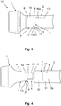
- FIG. 4 shows a third embodiment of the rotor cup 1 and the rotor shaft provided therefor 2.
- the rotor cup 1 and the rotor shaft 2 are shown separately and can as to FIG. 3 described to be connected to an open-end spinning rotor 14.
- In the second circumferential groove 12 of the extension 8 is used as a securing element 13 and as a connecting means 6 for axial connection present again arranged a snap ring 27.
- the extension 8 comprises an edged projection 16b, which is designed such that a torque-transmitting surface 19 is provided.
- the projection 16b thus forms a positive locking element 24 of the extension 8 in the present case.
- an angular recess 17b of the rotor shaft 2 is formed, which likewise constitutes a positive-locking element 24.
- the projection 16b and the recess 17b thus form connecting means 6 for torque transmission.
- a first circumferential groove 11 is formed for cooperation with the securing element 13 of the extension 8, which may have an oblique groove flank 18 or may be formed as a simple groove with straight flanks.
- the truncated cone-shaped receptacle 10 and the truncated conical extension 8 are provided.
- the extension 8 on the rotor shaft 2 and the receptacle 10 may be provided on the rotor cup 2.
- the groove 11 of the receptacle 10 may be formed with or without an oblique groove flank 18.
- a frustoconical extension 8 is formed on the rotor shaft 2 according to the foregoing description and the rotor cup 1 has the frusto-conical receptacle 10.
- the securing element 13 is provided in the second circumferential groove 12 of the extension 8.
- the snap ring 27 is then pressed against an oblique groove flank 18 of the receptacle 10 of the rotor cup 1, whereby an axial securing of the rotor cup 1 is reached on the rotor shaft.
- the inclined groove flank 18 can be formed with a circumferential groove 11.
- the frusto-conical extension 8 has no cylindrical projection 16a or angular projection 16b, but also a conical projection or extension, which is provided with a knurling or toothing as a positive-locking element 24.
- a corresponding recess 17 is provided in extension of the receptacle 10, which is also conical and which also has a knurling or toothing.
- the receptacle 10 with the recess 17 can also be provided by a separate component in the form of an insert which can be inserted into a bore of the rotor shaft 2.
- the form-locking elements 24 may be provided in the radial direction with a game.
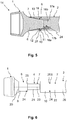
- FIG. 5 shows a fourth embodiment of the rotor cup 1 and the rotor shaft 2, wherein these are connected to the open-end spinning rotor 14.
- the rotor cup 1 has the extension 8 as well as a securing element 13 to the snap ring 27 arranged in the second circumferential groove 12.
- a cylindrical projection 16a is formed, in which now the angular recess 17b is formed.
- the rotor shaft 2 has the receptacle 10 and a cylindrical recess 17a in which an edged projection 16b corresponding to the angular recess 17a is formed.
- the edged projection 16b and the angular recess 17b thus each contain a positive locking element 24 and form again connecting means 6 for torque transmission.
- a non-positive torque transmission take place between the rotor cup 1 and the rotor shaft 2 through the snap ring 27 and the groove flank 18.
- the centering of the rotor cup 1 and the rotor shaft 2 is effected by the interaction of the frusto-conical extension 8 and the frusto-conical receptacle 10, to which, as described above, at least a part of the connecting means 6 is arranged at the same time or represent a part of the connecting means 6. Consequently, the centering means 7 and the connecting means 6 are partially formed in one piece. This commonality, the previously described embodiments 1 to 4.
- the FIG. 6 shows a fifth embodiment of the rotor cup 1 and the rotor shaft provided for the purpose 2.
- the centering means 7 comprise at least one separately formed from the connecting means 6 centering element 20.
- the centering element 20 comprises a cylindrical pin 21, which present in the rotor cup 1, in particular the extension 8, is pressed.
- the cylindrical pin 21 extends from the rotor cup 1 to beyond the extension 8 addition.
- a centering hole 22 is arranged as centering means 7, which corresponds to the cylindrical pin 21 of the rotor cup 1 and also forms a centering means 7.
- the cylindrical pin 21 has a pressure compensation bore 23.
- the pressure compensation bore 23 extends from the cylindrical pin 21 into the rotor cup 1, so that when connecting the rotor cup 1 to the rotor shaft 2, the air pressure is compensated.
- the coupling device 4 further comprises a form-fitting element 24 for transmitting torque from the rotor shaft 2 provided thereon to the rotor cup 1.
- a part of a dog clutch 25 is provided as positive-locking element 24 on the rotor cup 1 and correspondingly also on the rotor shaft 2.
- the positive-locking elements 24 thus form as well as the previously described edged recesses 17b and lugs 17a connecting means 6 for torque transmission.
- As a connecting means 6 for axial securing a magnet 26 is provided in the rotor shaft 2 in the present case.
- the dog clutch 25 is in the FIG. 13 shown in detail.
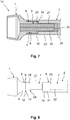
- FIG. 7 shows the open-end spinning rotor 14 with the rotor cup 1 and the rotor shaft 2 according to the FIG. 6 , in particular according to the fifth embodiment.
- the rotor cup 1 is connected via the connecting means 6 with the rotor shaft 2.
- the connection means 6 for transmitting torque are formed by the form-fitting elements 24 arranged on the extension 8 and the receptacle 10.
- the dog clutch 25 meshes with one another such that a transmission of the torque from the rotor shaft 2 to the rotor cup 1 can take place.
- the rotor cup 1 and the rotor shaft 2 are axially secured by a magnet 26 arranged in the rotor shaft 2, which thus forms a connection means 6 for axial securing.
- the centering of the rotor cup 1 by means of the cylindrical pin 21 of the rotor cup 1, which is arranged in the centering bore 22 of the rotor shaft 2.
- the centering element 20, in particular the cylindrical pin 21, is thus completely separate from the connecting means 6, in particular from the arranged on the extension 8 and the receptacle 10 form-fitting element 24 for transmitting torque and the magnet 26 for axial securing formed.
- the FIG. 8 shows the rotor cup 1 and the designated rotor shaft 2 according to a sixth embodiment.
- the rotor cup 1 in this case has the extension 8 with a part of a dog clutch 25 which is formed corresponding to a second part of the dog clutch 25 of the receptacle 10 of the rotor shaft 2. Furthermore, the extension 8, the second circumferential groove 12. In the second circumferential groove 12 is a securing element 13, in particular the O-ring 9, arranged.
- the receptacle 10 of the rotor shaft 2 has a first circumferential groove 11 into which the O-ring 9 is pressed, when the rotor cup 1 and the rotor shaft 2 are connected together to form the open-end spinning rotor 14.
- the axial securing of the rotor cup 1 on the rotor shaft 2 takes place here by the O-ring 9 and the grooves 11, 12 as connecting means 6 for axial securing.
- the reliable torque transmission is ensured by the coupled form-fitting elements 24, in particular the dog clutch 25, as a connecting means 6.
- the centering of the rotor cup 1 on the rotor shaft 2 is effected by the cylindrical pin 21 and the centering bore 22 as centering means 7, which is to receive the cylindrical pin 21.
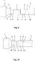
- FIG. 9 shows a seventh embodiment of the rotor cup 1 and the rotor shaft 2.
- the rotor cup contrary to the previously described embodiments, no positive-locking element 24.
- the axial securing of the rotor cup 1 on the rotor shaft 2 takes place here only by the O-ring 9 or another securing element 13 for axial securing, which is or, which is received in the connected state of the first and second circumferential groove 11, 12.
- the centering of the rotor cup 1 and the rotor shaft 2 is further carried out by the cylindrical pin 21 and the corresponding centering bore 22 as centering 7.
- the snap ring 27 cooperates with the oblique groove flank 18 according to the FIGS. 3 and 4 ,
- the embodiments comprising the first circumferential groove 11 and the second circumferential groove 12 may each be changed so that one of the circumferential grooves 11, 12 is replaced or supplemented by the oblique groove flank 18, so that the cooperation with the snap ring 27 can be realized.
- the snap ring 27 is arranged in the remaining first or second circumferential groove 11, 12.
- the FIG. 10 shows an eighth embodiment of the rotor cup 1 and the rotor shaft 2.
- the rotor cup 1 has the extension 8, in which the centering bore 22 is formed. Furthermore, the extension 8, the positive-locking element 24 as a connecting element 6 for torque transmission. Furthermore, a magnet 26 is arranged as a connecting element 6 for axial connection in the rotor cup 1.
- the rotor shaft 2 comprises the receptacle 10, wherein in the receptacle 10 of the cylindrical pin 21 is formed. In the receptacle 10, the positive-locking element 24 is also arranged.
- FIG. 11 shows a ninth embodiment of the rotor cup 1 and the rotor shaft 2.
- a securing element 13 in particular an O-ring 9 or snap ring 27, as a connecting element 6 to the axial Arranged connection.
- the centering is again via separate centering 7, namely the cylindrical pin 21 and the center hole 22nd
- FIG. 12 shows a tenth embodiment of the rotor cup 1 and the rotor shaft 2.
- the cylindrical pin 21 is arranged, which is introduced to connect the rotor shaft 2 with the rotor cup 1 in the centering bore 22.
- the centering of the rotor cup 1 and the rotor shaft by means of the cylindrical pin 21 and the center hole 22nd
- FIG. 13 shows the rotor cup 1, which carries the dog clutch 25 in the form of a toothing. Furthermore, the rotor cup 1, the cylindrical extension 8 and the pressed therein cylindrical pin 21 according to the FIG. 6 on.
- the dog clutch 25 is formed as a positive-locking element 24, by means of which the rotor cup 1 rotatably with the rotor shaft 2 according to the figure 6 can be connected.
- the rotor shaft 2 in this case has a toothing corresponding to the dog clutch 25.
- FIG. 14 finally shows yet another embodiment of the rotor cup 1 and the rotor shaft provided therefor 2.
- the open-end spinning rotor 14 of FIG. 14 essentially corresponds to that of FIG. 3 , so that in the following only the differences to the execution of the FIG. 3 to be discribed.
- FIG. 14 can be removed, the frustoconical extension 8 of the rotor cup 1 while near the beginning of the extension 8 to a circumferential elevation 28, which is designed here as a round bead. In this way, a defined contact area between the frusto-conical extension 8 and the truncated cone-shaped receptacle 10 of the rotor shaft 2 can be created.
- the maintenance of the rotor cup 1 in the rotor shaft 2 can thereby be improved, even if, as in the present case, only a small axial clamping force can be applied by the axial securing element 13.
- the securing element 13 may be designed as a snap ring 27 or as an elastic O-ring, which in turn pulls the rotor cup axially into the rotor shaft 2 through the circumferential groove 11 with the oblique groove flank 18 and at the same time forms a rotation lock between the rotor shaft 2 and the rotor cup 1.
- the elevation 28 may be formed instead of a round bead or instead of a semicircular profile by a rectangular or trapezoidal, circumferential elevation 28 in cross-section.
Landscapes
- Engineering & Computer Science (AREA)
- Mechanical Engineering (AREA)
- Textile Engineering (AREA)
- General Engineering & Computer Science (AREA)
- Spinning Or Twisting Of Yarns (AREA)
Applications Claiming Priority (1)
| Application Number | Priority Date | Filing Date | Title |
|---|---|---|---|
| DE102016122595.9A DE102016122595A1 (de) | 2016-11-23 | 2016-11-23 | Rotortasse und Offenend-Spinnrotor mit einer Rotortasse |
Publications (1)
| Publication Number | Publication Date |
|---|---|
| EP3327187A1 true EP3327187A1 (fr) | 2018-05-30 |
Family
ID=60327204
Family Applications (1)
| Application Number | Title | Priority Date | Filing Date |
|---|---|---|---|
| EP17201832.7A Withdrawn EP3327187A1 (fr) | 2016-11-23 | 2017-11-15 | Cloche de rotor et rotor pour métier à filer à bout libre doté d'une cloche de rotor |
Country Status (4)
| Country | Link |
|---|---|
| US (1) | US20180142736A1 (fr) |
| EP (1) | EP3327187A1 (fr) |
| CN (1) | CN108085801A (fr) |
| DE (1) | DE102016122595A1 (fr) |
Cited By (2)
| Publication number | Priority date | Publication date | Assignee | Title |
|---|---|---|---|---|
| WO2020084040A1 (fr) * | 2018-10-24 | 2020-04-30 | Hans Heidolph GmbH | Appareil d'agitation et/ou mélangeur |
| EP4733456A1 (fr) * | 2024-10-22 | 2026-04-29 | Rieter AG | Rotor de filage à bout libre, arbre de rotor et rotor pour un rotor de filage à bout libre |
Families Citing this family (5)
| Publication number | Priority date | Publication date | Assignee | Title |
|---|---|---|---|---|
| DE102017129152A1 (de) * | 2017-12-07 | 2019-06-13 | Maschinenfabrik Rieter Ag | Auflösewalze für eine Offenend-Spinnvorrichtung sowie Offenend-Spinnvorrichtung |
| DE102018007453A1 (de) * | 2018-09-20 | 2020-03-26 | Saurer Spinning Solutions Gmbh & Co. Kg | Halter zum Rotieren einer Rotortasse eines Spinnrotors, Spinnrotor und Verfahren zur Herstellung einer Pressverbindung zwischen einer Rotortasse und einem Halter |
| DE102018124947A1 (de) * | 2018-10-10 | 2020-04-16 | Maschinenfabrik Rieter Ag | Verfahren zum Überprüfen eines Montagezustands eines Spinnrotors einer Offenendspinnvorrichtung sowie Offenendspinnvorrichtung |
| EP3963224B1 (fr) * | 2019-04-30 | 2024-06-26 | Mtd Products Inc. | Raccord arbre/moyeu non rotatif |
| CN113153921A (zh) * | 2021-04-28 | 2021-07-23 | 浙江意动科技股份有限公司 | 一种新型传扭连接结构 |
Citations (5)
| Publication number | Priority date | Publication date | Assignee | Title |
|---|---|---|---|---|
| CH493653A (de) * | 1967-06-05 | 1970-07-15 | Tmm Research Ltd | Verfahren zum Entfernen der Fasern von der Fasersammelfläche des Läufers einer Offenend-Spinnvorrichtung bei einem Spinnunterbruch und Offenend-Spinnvorrichtung zur Durchführung dieses Verfahrens |
| DE3815182A1 (de) * | 1988-05-04 | 1989-11-16 | Wolfgang Grahamer | Spinnrotor |
| DE102009048295A1 (de) * | 2009-10-05 | 2010-07-29 | Oerlikon Textile Gmbh & Co. Kg | Offenend-Spinnrotor |
| EP2832903A1 (fr) * | 2013-07-31 | 2015-02-04 | Maschinenfabrik Rieter Ag | Rotor de métiers à filer à bout libre doté d'une coupelle de rotor, d'un arbre de rotor et d'un dispositif de couplage |
| EP2730686B1 (fr) * | 2012-11-10 | 2015-12-16 | Saurer Germany GmbH & Co. KG | Rotor de filage à extrémité ouverte |
Family Cites Families (5)
| Publication number | Priority date | Publication date | Assignee | Title |
|---|---|---|---|---|
| DE19621190A1 (de) * | 1996-05-25 | 1997-11-27 | Rieter Ingolstadt Spinnerei | Offenend-Spinnrotor |
| DE10024020A1 (de) | 2000-05-16 | 2001-11-22 | Schlafhorst & Co W | Offenend-Spinnrotor |
| CN1380500A (zh) * | 2001-04-10 | 2002-11-20 | 里特埃利特斯公司 | 高速轴承,尤其用于安装自由端纺纱机的纺纱转子 |
| DE102004007758A1 (de) * | 2004-02-18 | 2005-09-08 | Texparts Gmbh | Lagervorrichtung zur Lagerung eines hochtourig laufenden Rotors |
| DE102005062196A1 (de) * | 2005-12-23 | 2007-06-28 | Saurer Gmbh & Co. Kg | Offenend-Spinnrotor für eine Kreuzspulen herstellende Textilmaschine |
-
2016
- 2016-11-23 DE DE102016122595.9A patent/DE102016122595A1/de not_active Withdrawn
-
2017
- 2017-11-13 CN CN201711117739.0A patent/CN108085801A/zh active Pending
- 2017-11-15 EP EP17201832.7A patent/EP3327187A1/fr not_active Withdrawn
- 2017-11-21 US US15/818,851 patent/US20180142736A1/en not_active Abandoned
Patent Citations (5)
| Publication number | Priority date | Publication date | Assignee | Title |
|---|---|---|---|---|
| CH493653A (de) * | 1967-06-05 | 1970-07-15 | Tmm Research Ltd | Verfahren zum Entfernen der Fasern von der Fasersammelfläche des Läufers einer Offenend-Spinnvorrichtung bei einem Spinnunterbruch und Offenend-Spinnvorrichtung zur Durchführung dieses Verfahrens |
| DE3815182A1 (de) * | 1988-05-04 | 1989-11-16 | Wolfgang Grahamer | Spinnrotor |
| DE102009048295A1 (de) * | 2009-10-05 | 2010-07-29 | Oerlikon Textile Gmbh & Co. Kg | Offenend-Spinnrotor |
| EP2730686B1 (fr) * | 2012-11-10 | 2015-12-16 | Saurer Germany GmbH & Co. KG | Rotor de filage à extrémité ouverte |
| EP2832903A1 (fr) * | 2013-07-31 | 2015-02-04 | Maschinenfabrik Rieter Ag | Rotor de métiers à filer à bout libre doté d'une coupelle de rotor, d'un arbre de rotor et d'un dispositif de couplage |
Cited By (2)
| Publication number | Priority date | Publication date | Assignee | Title |
|---|---|---|---|---|
| WO2020084040A1 (fr) * | 2018-10-24 | 2020-04-30 | Hans Heidolph GmbH | Appareil d'agitation et/ou mélangeur |
| EP4733456A1 (fr) * | 2024-10-22 | 2026-04-29 | Rieter AG | Rotor de filage à bout libre, arbre de rotor et rotor pour un rotor de filage à bout libre |
Also Published As
| Publication number | Publication date |
|---|---|
| CN108085801A (zh) | 2018-05-29 |
| US20180142736A1 (en) | 2018-05-24 |
| DE102016122595A1 (de) | 2018-05-24 |
Similar Documents
| Publication | Publication Date | Title |
|---|---|---|
| EP3327187A1 (fr) | Cloche de rotor et rotor pour métier à filer à bout libre doté d'une cloche de rotor | |
| DE10304124B4 (de) | Differentialbaugruppe | |
| EP1502008A1 (fr) | Dispositif permettant de fixer un rotor sur un arbre | |
| AT512211B1 (de) | Synchronisiereinrichtung zwischen zwei drehenden bauteilen | |
| DE102016220472A1 (de) | Schnellwechselkupplung für eine Behälterbehandlungsmaschine | |
| DE102013224191A1 (de) | Welle-Nabe-Fügeverbindung und Verfahren zur Herstellung derselben | |
| DE102009051707A1 (de) | Mehrfachsynchronisationsbaugruppe eines Schaltgetriebes und Schaltgetriebe | |
| DE102006062240B4 (de) | Lösbare Kupplung | |
| EP3325834B1 (fr) | Système pour relier à rotation une machine de charge d'un banc de test à un échantillon | |
| DE102008047017A1 (de) | Kreiskeil-Verbindung | |
| DE19542079A1 (de) | Lagerung für einen Offenend-Spinnrotor | |
| DE102013213514A1 (de) | Sicherungsvorrichtung zum Sichern einer Mutter gegen ungewolltes Losdrehen, sowie Lageranordnung einer Welle | |
| EP3111101B1 (fr) | Agencement de paliers coniques et procédé de réglage de précontrainte | |
| DE102015115001A1 (de) | Riemenscheiben-Baugruppe | |
| EP3249085A2 (fr) | Arbre de rotor pour un rotor de filage monté sans contact dans un système de paliers magnétiques et rotor de filage | |
| EP3325835B1 (fr) | Dispositif de raccordement d'arbre et système pour raccorder à rotation une machine de charge d'un banc de test à un échantillon | |
| DE102018216910A1 (de) | Übersetzungsgetriebe für ein Fahrzeug mit einer Elektromaschine | |
| EP1886047B1 (fr) | Systeme differentiel a ouvertures de montage | |
| AT286718B (de) | Spann- oder Klemmhülse | |
| DE10343074B4 (de) | Gekoppelte Synchronisiereinrichtung | |
| EP0644347B1 (fr) | Accouplement de compensation | |
| EP1552175A1 (fr) | Joint de cardan de type rzeppa | |
| DE102020104597A1 (de) | Taumelgetriebe für Verstellvorrichtungen | |
| EP3835609B1 (fr) | Dispositif de synchronisation | |
| DE102009039934A1 (de) | Synchronisiereinrichtung und Getriebe |
Legal Events
| Date | Code | Title | Description |
|---|---|---|---|
| PUAI | Public reference made under article 153(3) epc to a published international application that has entered the european phase |
Free format text: ORIGINAL CODE: 0009012 |
|
| STAA | Information on the status of an ep patent application or granted ep patent |
Free format text: STATUS: THE APPLICATION HAS BEEN PUBLISHED |
|
| AK | Designated contracting states |
Kind code of ref document: A1 Designated state(s): AL AT BE BG CH CY CZ DE DK EE ES FI FR GB GR HR HU IE IS IT LI LT LU LV MC MK MT NL NO PL PT RO RS SE SI SK SM TR |
|
| AX | Request for extension of the european patent |
Extension state: BA ME |
|
| STAA | Information on the status of an ep patent application or granted ep patent |
Free format text: STATUS: REQUEST FOR EXAMINATION WAS MADE |
|
| 17P | Request for examination filed |
Effective date: 20181123 |
|
| RBV | Designated contracting states (corrected) |
Designated state(s): AL AT BE BG CH CY CZ DE DK EE ES FI FR GB GR HR HU IE IS IT LI LT LU LV MC MK MT NL NO PL PT RO RS SE SI SK SM TR |
|
| STAA | Information on the status of an ep patent application or granted ep patent |
Free format text: STATUS: EXAMINATION IS IN PROGRESS |
|
| 17Q | First examination report despatched |
Effective date: 20200713 |
|
| GRAP | Despatch of communication of intention to grant a patent |
Free format text: ORIGINAL CODE: EPIDOSNIGR1 |
|
| STAA | Information on the status of an ep patent application or granted ep patent |
Free format text: STATUS: GRANT OF PATENT IS INTENDED |
|
| INTG | Intention to grant announced |
Effective date: 20210304 |
|
| INTG | Intention to grant announced |
Effective date: 20210315 |
|
| STAA | Information on the status of an ep patent application or granted ep patent |
Free format text: STATUS: THE APPLICATION IS DEEMED TO BE WITHDRAWN |
|
| 18D | Application deemed to be withdrawn |
Effective date: 20210727 |