EP2732999A2 - Améliorations apportées à une zone de stockage de marchandises - Google Patents
Améliorations apportées à une zone de stockage de marchandises Download PDFInfo
- Publication number
- EP2732999A2 EP2732999A2 EP20130193713 EP13193713A EP2732999A2 EP 2732999 A2 EP2732999 A2 EP 2732999A2 EP 20130193713 EP20130193713 EP 20130193713 EP 13193713 A EP13193713 A EP 13193713A EP 2732999 A2 EP2732999 A2 EP 2732999A2
- Authority
- EP
- European Patent Office
- Prior art keywords
- storage area
- panels
- access opening
- goods storage
- same
- Prior art date
- Legal status (The legal status is an assumption and is not a legal conclusion. Google has not performed a legal analysis and makes no representation as to the accuracy of the status listed.)
- Granted
Links
Images



Classifications
-
- B—PERFORMING OPERATIONS; TRANSPORTING
- B60—VEHICLES IN GENERAL
- B60J—WINDOWS, WINDSCREENS, NON-FIXED ROOFS, DOORS, OR SIMILAR DEVICES FOR VEHICLES; REMOVABLE EXTERNAL PROTECTIVE COVERINGS SPECIALLY ADAPTED FOR VEHICLES
- B60J5/00—Doors
- B60J5/10—Doors arranged at the vehicle rear
- B60J5/12—Doors arranged at the vehicle rear slidable; foldable
- B60J5/125—Doors arranged at the vehicle rear slidable; foldable for utility vehicles or public transport
-
- B—PERFORMING OPERATIONS; TRANSPORTING
- B60—VEHICLES IN GENERAL
- B60P—VEHICLES ADAPTED FOR LOAD TRANSPORTATION OR TO TRANSPORT, TO CARRY, OR TO COMPRISE SPECIAL LOADS OR OBJECTS
- B60P1/00—Vehicles predominantly for transporting loads and modified to facilitate loading, consolidating the load, or unloading
- B60P1/02—Vehicles predominantly for transporting loads and modified to facilitate loading, consolidating the load, or unloading with parallel up-and-down movement of load supporting or containing element
Definitions
- the invention to which this application relates is to improvements to a goods storage area and, in particular, although not necessarily exclusively, to a goods storage area in the form of a trailer which is provided to be moved by a road vehicle, along a road network.
- goods storage trailers are well known and the same can be provided in a number of different forms and sizes to suit the goods which are being carried therein, the distance for which the goods are to be carried and/or the access requirements at the locations for delivery and/or collection of goods.
- the available space within the goods storage area is sufficient to allow the cages to be positioned therein, there can often be a problem in moving the roll cages through the access openings to the goods storage area as the goods storage area is typically linked to the location at which the goods are to be stored subsequently, or obtained from, via a ramp.
- the location of the ramp typically causes the cages to be introduced into the goods storage area at an angle which means that the effective height of the cages at that time is greater than when the same are on a horizontal surface.
- a further problem which is experienced is with regard to the opening and closure of the access opening. This is conventionally achieved either by the use of hinged doors which are required to be typically moved about their respective hinges located at the side walls of the trailer goods storage area and at the edge of the opening. The doors are moved between the open and closed positions.
- a shutter arrangement is provided which comprises a series of elongate members which are joined together and which can be moved between a fully open position and a closed position closing the entre height of the opening.
- hinged doors it is found that where vehicle trailers are used to deliver and/or collect goods in relatively confined access areas, such as inner city areas or relatively small retail outlets, there can often not be sufficient space available to allow the doors to be swung outwardly outwith the side walls of the goods storage area in order to fully open the access opening. This can cause practical difficulties in delivering and/or collecting goods.
- the use of shutter assemblies does avoid this problem but the need to provide drive means to move the shutter system between the open and closed positions and furthermore the need to provide storage space for the shutter members when the shutter is in the open position means that the already limited space which is available within the goods storage area is further reduced by the requirement for the provision of the storage space for the shitter arrangement.
- a yet further problem which is experienced, particularly with goods storage areas which include first and second floors, is that while the provision of the second floor raised above the first floor does provide advantages in terms of use of the available space, it can be found that the fixed second floor is not sufficiently flexible in terms of its position within the goods storage area.
- An aim of the present invention is therefore to provide improvements which allow the use of the access opening, typically at the rear of the goods storage area, to be improved in terms of use, and accessibility of the same.
- a further aim is therefore to provide a system where by if a second floor is provided in the goods storage area, to allow the goods storage area to be more flexible.
- a goods storage area said storage area including a base, a roof, side walls and opposing end walls, one of said end walls including an access opening therein and a further floor is provided which is vertically spaced from, and located between, the base and the roof and wherein the access opening is provided with closure means which comprise first and second panels, said panels moveable between a first configuration in which the access opening is closed by the panels, a second configuration in which the panels at least partially overlap to allow the access opening to be open to allow access to the storage area defined between the base and the further floor, and a third configuration in which the panels at least partially overlap to allow the access opening to be open to allow access to the storage area defined between the further floor and the roof.
- the said panels are independently movable so as to achieve the required configuration of the same.
- the panels are manually movable.
- the movement of the panels is achieved by operation of a drive means.
- the panels are moveable along respective guide means provided at opposing edges of the same.
- the panels are mounted on pulleys in order to allow the same to be moved.
- the pulley members are attached to one or more weights.
- the weights are selected so as to act to balance against the weight of the panel and hence maintain the panels in the position to which the same have been moved until a further movement force is exerted thereon.
- the respective weights are retained so as to move in a predetermined path move when a movement force is exerted on a panel to move the same.
- the weights are enclosed with respective passages along which the same move and/or the weights are connected to a track along which the same move.
- locking means are provided in order to retain at least one of the panels in position in each configuration.
- the locking means which are provided are independently operable with respect to each panel.
- the locking means comprise at least one, but typically two shoot bolts, which, when moved to a locking position engage with an aperture provided in at the end wall adjacent the access opening.
- the locking means are provided with means to allow the same to be accessed by a person on the ground and/or on the base of the goods storage area to as to allow the means to be actuable by the person in order to operate the locking means regardless of the height of the panel with which the locking means is provided at that time.
- the said panels are offset in respect of a vertical plane so as to allow the same to be moved to overlapping positions.
- the said storage area includes a portion which is mounted on the further floor and/or a portion which is mounted on the roof and each portion which is provided is moveable between a first position in which the same is substantially in line with the remainder of the roof, or further floor, respectively and a second position in which at least part of the portion is raised.
- the panels are provided with respect to the access opening such that the panels can be moved to a location such that the top edges of the panels are higher than the inner face of the roof. In this arrangement so the panels can both be moved to a raised position such that the lower edge of the panels is in line with or above the said further floor portion when it is in the second raised position.
- apparatus for the closure of an access opening of a goods storage area comprising first and second panels, wherein said panels are moveable between a first configuration in which the access opening is closed by said panels, a second configuration in which the panels at least partially overlap to partially open the access opening and a third configuration, different to the second configuration, in which the panels at least partially overlap to partially open the access opening.
- the lower portion of the access opening in the second configuration is open and in the third configuration a higher portion of the access opening is open.
- the panels are of the same height.
- the panels may be formed of a unitary member or from a number of members joined together. However in each case the panels are not required to be folded, rolled or otherwise altered or stored in any of the required configurations of their use.
- a goods storage area including a base, a roof, side walls and opposing end walls, one of said end walls including an access opening therein and a further floor is provided which is vertically spaced from the base and wherein on one or both of the roof and further floor there is provided a portion which is movable between a first position in which the same is substantially in line with the remainder of the roof or further floor respectively and a second, raised position.
- the said portion is pivotally movable between the first and second portions.
- pivot axis extends across the width of the goods storage area.
- the portion is located at or adjacent to the access opening. In one embodiment the portion is formed across the width of the roof or further floor and has a free end at the access opening and extends inwardly to the pivot axis.
- the said free end is the highest point of the portion when the same is in the second position.
- the said portion is moved to the second position when loading and/or unloading goods to and from the respective floors so as to allow increased space to be available at the access opening and thereby ease or allow the movement of goods therethrough.
- the said portions are manually movable but provided with struts or stays to allow the same to be maintained in the second position until released.
- the said further floor is provided with at least one section which is movable along a predefined path so as to vary the spacing between that section and the base of the goods storage area.
- said section is provided in addition to the portion provided at the access opening, but this need not be the case.
- said section is movable along a vertical axis and allows the space which is available between the same and the base to be adjusted to allow either or both of greater room for manoeuvring of the goods and/or the space required for the storage of goods therein to be altered to take into account that particular load to be carried.
- the further floor is formed of one or a plurality of said sections.
- the access opening is provided with closure means which comprise first and second panels, said panels movable between a first configuration in which the access opening is closed, a second configuration in which the panels at least partially overlap to allow access to the storage area between the base and the further floor and a third configuration in which the panels at least partially overlap to allow access to the storage area between the further floor and the roof.
- the further floor is provided with at least one section which is movable along a predefined path so as to vary the spacing between that section and the first floor of the goods storage area.
- said section is movable along a vertical axis and allows the space which is available between the same and the base to be adjusted to allow either or both of greater room for manoeuvring of the goods and/or the space required for the storage of goods therein to be altered to take into account that particular load to be carried.
- the goods storage area in this embodiment is a trailer for transport by a vehicle and is defined end walls 8,10, the rear of which , 10 , is provided with an access opening 12.
- the goods storage area includes a roof 14 and side walls 16,18.
- the goods storage area also includes a base or first floor 4 and a second floor 6 vertically spaced from the first floor.
- the second floor includes a portion 20 which is movable with respect to the remainder of that floor as shown by arrows 22,24 as shown in Figure 1 .
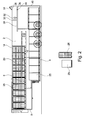
- Figure 2 illustrates the manner in which the goods storage area may include a further floor portion 28 which can also be moved in the vertical direction as indicated by arrows 30,32 to allow improved flexibility of the storage area.
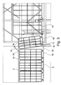
- the roof 14 and floor 6 are provided with respective portions 34,36. These portions are selectively movable about respective pivot axis 38, 40 which extend across the width of the storage area. The movement is between a first position in which the potions lie flush and in line with the remainder of the roof 14 and floor 6 respectively and a second position in which the free ends of the portions are raised as shown.
- Figure 4a-c there is illustrated the end wall 10 of the goods storage area and an access opening 12 with a closure assembly therefore in three configurations.
- Figure 4a illustrates the closure assembly in a closed position to close the access opening in which the same is closed by the position of first and second panels 44,46 positioned such that, in combination, the access opening is wholly closed.
- Figure 4b the closure assembly is shown in a configuration in which the panel 44 has been moved to overlap panel 46 and thereby allow an open area 48 to be created which allows access to the higher storage area 50 defined between the floor 6 and roof 14.
- Figure 4c the third configuration is shown in which the panel 46 has been moved to overlap the panel 44 to allow an opening 52 to be created which allows access to the lower storage area 54 between the base floor 4 and the underside of floor 6.
- the panels 44,46 are offset with regard to a vertical plane, so the panels can be housed largely within the area of the end 10 of the storage area.
- the panels can be moved such that the top edge of the panels are moved above the top of the access opening.
- the lower edge of the panels 44,46 are higher than the level of the floor 6 and can be held at a position which is equal to the height of the raised portion 36 as shown in Figure 1 in which the portion has been raised the distance X.
- This means that the advantage of the provision of the portion 36 is obtained due to the ability to raise the panels 44,46 higher.
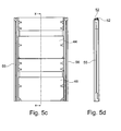
- Figures 5a-d illustrate views of the closure assembly and shows the panels 44,46 in the fully closed position as illustrated in Figure 4a
- the panels are moved via guide means, and driven, typically by one or more pulleys, 52 and chains or ropes 54 which are located at opposing edges 55,56 of the closure assembly panels.
- Handles 58 can be provided on the panels to allow the same to be grasped for movement between the configurations.
- the movement can be powered by drive means which may, in one embodiment be located at the underside of the goods storage area, but, more typically will be manually movable. In either case the closure assembly ensures that all of the goods storage area is still available for the storage of goods therein.
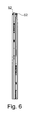
- Figure 6 illustrates a cross section along the line XX.
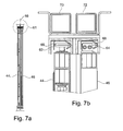
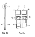
- Figures 7a-b and 8a-b there is illustrated in Figures 7a and 8a a plan view of the closure assembly and which illustrates the manner in which the panels 44,46 are offset to each other along the plane 59.
- the figures 7b and 8b illustrate a detailed view of one side of the panels and guide and movement arrangement therefore as illustrated by the circle 61.
- the panels 44, 46 are provided to be movable along respective guide means 62, 64 at each edge.
- the panels are provided with rollers 66,68 which engage in the respective guide means and roll along the same so as to provide guide movement of the panels between the different configurations.
- first and second passages 70, 72 for the respective panels.
- Each of the passages receives at least one weight (not shown) which is connected to a pulley rope (not shown).
- a weight not shown
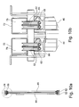
- Figure 10a shows a similar view to that shown in Figures 7a and 8a
- Figure 10b illustrates the detail of one edge 55 of the closure assembly as indicated by circle 74. In this case the same features are illustrated using the same reference numbers.
- pulleys 52 are illustrated for each of the panels. The pulleys receive respective ropes or chains therearound. One end of the rope or chain is attached to the panel and the rope or chain is attached to the weights 76.
- the movement of the panel along the guide means can be achieved and the weights will move along the respective passage 70,72 so as to balance the movement and retain the panels at the desired height.
- the pulleys are provided at each edge of the panels along with the weight arrangements.
- the arrangement which can be used to allow movement of the respective panels is in one embodiment similar to the weight and pulley arrangement which is used in relation to a sash window movement mechanism.
- each of the panels 44,46 is independently movable.
- locking means can be provided for each of the panels.
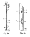
- Figures 9a and b illustrate one of the panels 46 is shown with locking means 78 is shown.
- the locking means includes first and second opposing shoot bolts 80,82 which are movable as indicated by respective arrows 84,86. When in a locking position the shoot bolt free end 88 engages in an aperture in the guide means 64 at the edge 55 and the free end 90 of the shoot bolt 82 engages in an aperture in the guide means 64 at edge 56. When engaged the panel is prevented from moving up and down along the guide means. When disengaged the panels are free to move.
- a handle assembly 60 is provided at the centre of the panel and as shown in more detail in Figure 9b .
- the handle assembly is rotatable about axis 90 and, via joints 92, 94 can cause the shoot bolts 80, 82 to be moved out or moved in to engage and disengage the same as appropriate.
- the handle assembly 60 is provided with actuation means such as a strap (not shown) which can extend downwardly from the panel to a sufficient extent so as to allow the same to be grasped and used by a person to actuate the locking means when the person is positioned on the ground.
Landscapes
- Engineering & Computer Science (AREA)
- Mechanical Engineering (AREA)
- Transportation (AREA)
- Warehouses Or Storage Devices (AREA)
- Floor Finish (AREA)
Applications Claiming Priority (1)
| Application Number | Priority Date | Filing Date | Title |
|---|---|---|---|
| GB201220864A GB201220864D0 (en) | 2012-11-20 | 2012-11-20 | Improvements to agoods storage area |
Publications (3)
| Publication Number | Publication Date |
|---|---|
| EP2732999A2 true EP2732999A2 (fr) | 2014-05-21 |
| EP2732999A3 EP2732999A3 (fr) | 2015-10-21 |
| EP2732999B1 EP2732999B1 (fr) | 2019-02-06 |
Family
ID=47521442
Family Applications (1)
| Application Number | Title | Priority Date | Filing Date |
|---|---|---|---|
| EP13193713.8A Active EP2732999B1 (fr) | 2012-11-20 | 2013-11-20 | Améliorations apportées à une zone de stockage de marchandises |
Country Status (2)
| Country | Link |
|---|---|
| EP (1) | EP2732999B1 (fr) |
| GB (1) | GB201220864D0 (fr) |
Cited By (6)
| Publication number | Priority date | Publication date | Assignee | Title |
|---|---|---|---|---|
| GB2532839A (en) * | 2014-11-19 | 2016-06-01 | Mark Adams William | Improvements to transport goods trailer |
| EP3078618A1 (fr) | 2015-04-09 | 2016-10-12 | William Mark Adams | Appareil de mouvement de marchandises |
| WO2017153714A1 (fr) | 2016-03-11 | 2017-09-14 | William Mark Adams | Appareil de déplacement de marchandises |
| WO2017182768A1 (fr) | 2016-04-19 | 2017-10-26 | William Mark Adams | Appareil destiné à être utilisé pour déterminer le poids d'une remorque et des marchandises qu'elle contient |
| WO2018193264A1 (fr) | 2017-04-21 | 2018-10-25 | William Mark Adams | Améliorations apportées à un appareil de déplacement de marchandises |
| US10479665B2 (en) * | 2016-05-26 | 2019-11-19 | William Mark Adams | Goods movement apparatus |
Family Cites Families (5)
| Publication number | Priority date | Publication date | Assignee | Title |
|---|---|---|---|---|
| US908199A (en) * | 1908-08-28 | 1908-12-29 | Charles O Birney | Car-end construction. |
| AU441612B2 (en) * | 1971-03-19 | 1973-10-17 | FREDERICK KEONG and ANN IRENE KEONG JOHN | Stock crate |
| GB2172873B (en) * | 1985-03-21 | 1988-04-07 | Tidd Strongbox Ltd | Vehicle body |
| JPH0338216U (fr) * | 1989-08-28 | 1991-04-12 | ||
| FR2814120B1 (fr) * | 2000-09-19 | 2003-03-21 | Renault | Ouvrant de vehicule automobile |
-
2012
- 2012-11-20 GB GB201220864A patent/GB201220864D0/en not_active Ceased
-
2013
- 2013-11-20 EP EP13193713.8A patent/EP2732999B1/fr active Active
Non-Patent Citations (1)
| Title |
|---|
| None |
Cited By (10)
| Publication number | Priority date | Publication date | Assignee | Title |
|---|---|---|---|---|
| GB2532839A (en) * | 2014-11-19 | 2016-06-01 | Mark Adams William | Improvements to transport goods trailer |
| GB2532839B (en) * | 2014-11-19 | 2017-02-08 | Mark Adams William | Improvements to transport goods trailer |
| EP3078618A1 (fr) | 2015-04-09 | 2016-10-12 | William Mark Adams | Appareil de mouvement de marchandises |
| GB2540923A (en) * | 2015-04-09 | 2017-02-08 | Mark Adams William | Goods movement apparatus |
| EP3190002A1 (fr) | 2015-04-09 | 2017-07-12 | William Mark Adams | Appareil de mouvement de marchandises |
| WO2017153714A1 (fr) | 2016-03-11 | 2017-09-14 | William Mark Adams | Appareil de déplacement de marchandises |
| EP3426581A1 (fr) * | 2016-03-11 | 2019-01-16 | William Mark Adams | Appareil de déplacement de marchandises |
| WO2017182768A1 (fr) | 2016-04-19 | 2017-10-26 | William Mark Adams | Appareil destiné à être utilisé pour déterminer le poids d'une remorque et des marchandises qu'elle contient |
| US10479665B2 (en) * | 2016-05-26 | 2019-11-19 | William Mark Adams | Goods movement apparatus |
| WO2018193264A1 (fr) | 2017-04-21 | 2018-10-25 | William Mark Adams | Améliorations apportées à un appareil de déplacement de marchandises |
Also Published As
| Publication number | Publication date |
|---|---|
| EP2732999B1 (fr) | 2019-02-06 |
| GB201220864D0 (en) | 2013-01-02 |
| EP2732999A3 (fr) | 2015-10-21 |
Similar Documents
| Publication | Publication Date | Title |
|---|---|---|
| EP2732999B1 (fr) | Améliorations apportées à une zone de stockage de marchandises | |
| CA2703219C (fr) | Appareil de manutention de chargement | |
| US4966510A (en) | Trailer for transporting golf carts and the like | |
| US9265979B2 (en) | Firefighting or rescue apparatus including side access ladder | |
| US8678411B2 (en) | Retractable stairs for a truck or trailer | |
| CN107013045B (zh) | 装载平台 | |
| US11827447B2 (en) | Telescoping container system | |
| US11319713B2 (en) | Elevating cage with pivotably attached panels having respective pivotable latches | |
| US20120048648A1 (en) | Pivoting handrail system | |
| JP6061214B2 (ja) | 複数デッキ型貨物専用コンテナ | |
| EP2855201B1 (fr) | Système de plateforme pour un compartiment de cargaison d'un camion, d'un poids lourd ou d'une remorque | |
| US20120006618A1 (en) | Cement industry gangway and safety cage | |
| WO2010146089A1 (fr) | Système de transport | |
| AU2010215087B2 (en) | Logistics panel and containers | |
| US20160375748A1 (en) | Apparatus and method for distributing a tarp over a cargo on a truck load bed | |
| CN108076638A (zh) | 用于船运集装箱的便携式升降装置 | |
| US7168119B1 (en) | Aircraft passenger boarding bridge having a chute for transport of baggage between boarding bridge and ground level | |
| DE202006008383U1 (de) | Kombination von Dachbodenleiter und Aufzug | |
| KR101946962B1 (ko) | 자바라 타입의 블라인드가 구비된 특장차 | |
| EP3078618B1 (fr) | Appareil de mouvement de marchandises | |
| DE2018508A1 (de) | Umzugsmaschine | |
| KR20210001359A (ko) | 화물차의 슬라이딩 커튼 탑 | |
| AU2005100397B4 (en) | Trailer | |
| DE10314378A1 (de) | Aufbau für einen Lastkraftwagen oder einen Anhänger für Lastkraftwagen | |
| DE202023107000U1 (de) | Ladeschlitten für den Transport eines Landfahrzeugs in einem Container sowie Transportsystem mit einem Container und dem Ladeschlitten |
Legal Events
| Date | Code | Title | Description |
|---|---|---|---|
| PUAI | Public reference made under article 153(3) epc to a published international application that has entered the european phase |
Free format text: ORIGINAL CODE: 0009012 |
|
| 17P | Request for examination filed |
Effective date: 20131120 |
|
| AK | Designated contracting states |
Kind code of ref document: A2 Designated state(s): AL AT BE BG CH CY CZ DE DK EE ES FI FR GB GR HR HU IE IS IT LI LT LU LV MC MK MT NL NO PL PT RO RS SE SI SK SM TR |
|
| AX | Request for extension of the european patent |
Extension state: BA ME |
|
| RIC1 | Information provided on ipc code assigned before grant |
Ipc: B60P 1/26 20060101ALI20150513BHEP Ipc: B60P 1/02 20060101ALI20150513BHEP Ipc: B60J 5/12 20060101AFI20150513BHEP |
|
| PUAL | Search report despatched |
Free format text: ORIGINAL CODE: 0009013 |
|
| AK | Designated contracting states |
Kind code of ref document: A3 Designated state(s): AL AT BE BG CH CY CZ DE DK EE ES FI FR GB GR HR HU IE IS IT LI LT LU LV MC MK MT NL NO PL PT RO RS SE SI SK SM TR |
|
| AX | Request for extension of the european patent |
Extension state: BA ME |
|
| RIC1 | Information provided on ipc code assigned before grant |
Ipc: B60J 5/12 20060101AFI20150914BHEP Ipc: B60P 1/02 20060101ALI20150914BHEP Ipc: B60P 1/26 20060101ALI20150914BHEP |
|
| R17P | Request for examination filed (corrected) |
Effective date: 20151111 |
|
| 111L | Licence recorded |
Designated state(s): AL AT BE BG CH CY CZ DE DK EE ES FI FR GB GR HR HU IE IS IT LT LU LV MC MK MT NL NO PL PT RO RS SE SI SK SM TR Free format text: EXCLUSIVE LICENSE Name of requester: TRANSDEK UK LIMITED, GB Effective date: 20160506 |
|
| STAA | Information on the status of an ep patent application or granted ep patent |
Free format text: STATUS: EXAMINATION IS IN PROGRESS |
|
| 17Q | First examination report despatched |
Effective date: 20180514 |
|
| GRAP | Despatch of communication of intention to grant a patent |
Free format text: ORIGINAL CODE: EPIDOSNIGR1 |
|
| STAA | Information on the status of an ep patent application or granted ep patent |
Free format text: STATUS: GRANT OF PATENT IS INTENDED |
|
| INTG | Intention to grant announced |
Effective date: 20181031 |
|
| GRAS | Grant fee paid |
Free format text: ORIGINAL CODE: EPIDOSNIGR3 |
|
| GRAA | (expected) grant |
Free format text: ORIGINAL CODE: 0009210 |
|
| STAA | Information on the status of an ep patent application or granted ep patent |
Free format text: STATUS: THE PATENT HAS BEEN GRANTED |
|
| 111L | Licence recorded |
Designated state(s): AL AT BE BG CH CY CZ DE DK EE ES FI FR GB GR HR HU IE IS IT LT LU LV MC MK MT NL NO PL PT RO RS SE SI SK SM TR Free format text: EXCLUSIVE LICENSE Name of requester: TRANSDEK UK LIMITED, GB Effective date: 20160506 |
|
| AK | Designated contracting states |
Kind code of ref document: B1 Designated state(s): AL AT BE BG CH CY CZ DE DK EE ES FI FR GB GR HR HU IE IS IT LI LT LU LV MC MK MT NL NO PL PT RO RS SE SI SK SM TR |
|
| REG | Reference to a national code |
Ref country code: GB Ref legal event code: FG4D |
|
| REG | Reference to a national code |
Ref country code: CH Ref legal event code: EP Ref country code: AT Ref legal event code: REF Ref document number: 1094669 Country of ref document: AT Kind code of ref document: T Effective date: 20190215 |
|
| REG | Reference to a national code |
Ref country code: IE Ref legal event code: FG4D |
|
| REG | Reference to a national code |
Ref country code: DE Ref legal event code: R096 Ref document number: 602013050452 Country of ref document: DE |
|
| REG | Reference to a national code |
Ref country code: NL Ref legal event code: MP Effective date: 20190206 |
|
| REG | Reference to a national code |
Ref country code: LT Ref legal event code: MG4D |
|
| PG25 | Lapsed in a contracting state [announced via postgrant information from national office to epo] |
Ref country code: NL Free format text: LAPSE BECAUSE OF FAILURE TO SUBMIT A TRANSLATION OF THE DESCRIPTION OR TO PAY THE FEE WITHIN THE PRESCRIBED TIME-LIMIT Effective date: 20190206 Ref country code: SE Free format text: LAPSE BECAUSE OF FAILURE TO SUBMIT A TRANSLATION OF THE DESCRIPTION OR TO PAY THE FEE WITHIN THE PRESCRIBED TIME-LIMIT Effective date: 20190206 Ref country code: LT Free format text: LAPSE BECAUSE OF FAILURE TO SUBMIT A TRANSLATION OF THE DESCRIPTION OR TO PAY THE FEE WITHIN THE PRESCRIBED TIME-LIMIT Effective date: 20190206 Ref country code: FI Free format text: LAPSE BECAUSE OF FAILURE TO SUBMIT A TRANSLATION OF THE DESCRIPTION OR TO PAY THE FEE WITHIN THE PRESCRIBED TIME-LIMIT Effective date: 20190206 Ref country code: PT Free format text: LAPSE BECAUSE OF FAILURE TO SUBMIT A TRANSLATION OF THE DESCRIPTION OR TO PAY THE FEE WITHIN THE PRESCRIBED TIME-LIMIT Effective date: 20190606 Ref country code: NO Free format text: LAPSE BECAUSE OF FAILURE TO SUBMIT A TRANSLATION OF THE DESCRIPTION OR TO PAY THE FEE WITHIN THE PRESCRIBED TIME-LIMIT Effective date: 20190506 |
|
| REG | Reference to a national code |
Ref country code: AT Ref legal event code: MK05 Ref document number: 1094669 Country of ref document: AT Kind code of ref document: T Effective date: 20190206 |
|
| PG25 | Lapsed in a contracting state [announced via postgrant information from national office to epo] |
Ref country code: IS Free format text: LAPSE BECAUSE OF FAILURE TO SUBMIT A TRANSLATION OF THE DESCRIPTION OR TO PAY THE FEE WITHIN THE PRESCRIBED TIME-LIMIT Effective date: 20190606 Ref country code: GR Free format text: LAPSE BECAUSE OF FAILURE TO SUBMIT A TRANSLATION OF THE DESCRIPTION OR TO PAY THE FEE WITHIN THE PRESCRIBED TIME-LIMIT Effective date: 20190507 Ref country code: LV Free format text: LAPSE BECAUSE OF FAILURE TO SUBMIT A TRANSLATION OF THE DESCRIPTION OR TO PAY THE FEE WITHIN THE PRESCRIBED TIME-LIMIT Effective date: 20190206 Ref country code: HR Free format text: LAPSE BECAUSE OF FAILURE TO SUBMIT A TRANSLATION OF THE DESCRIPTION OR TO PAY THE FEE WITHIN THE PRESCRIBED TIME-LIMIT Effective date: 20190206 Ref country code: RS Free format text: LAPSE BECAUSE OF FAILURE TO SUBMIT A TRANSLATION OF THE DESCRIPTION OR TO PAY THE FEE WITHIN THE PRESCRIBED TIME-LIMIT Effective date: 20190206 Ref country code: BG Free format text: LAPSE BECAUSE OF FAILURE TO SUBMIT A TRANSLATION OF THE DESCRIPTION OR TO PAY THE FEE WITHIN THE PRESCRIBED TIME-LIMIT Effective date: 20190506 |
|
| PG25 | Lapsed in a contracting state [announced via postgrant information from national office to epo] |
Ref country code: RO Free format text: LAPSE BECAUSE OF FAILURE TO SUBMIT A TRANSLATION OF THE DESCRIPTION OR TO PAY THE FEE WITHIN THE PRESCRIBED TIME-LIMIT Effective date: 20190206 Ref country code: CZ Free format text: LAPSE BECAUSE OF FAILURE TO SUBMIT A TRANSLATION OF THE DESCRIPTION OR TO PAY THE FEE WITHIN THE PRESCRIBED TIME-LIMIT Effective date: 20190206 Ref country code: ES Free format text: LAPSE BECAUSE OF FAILURE TO SUBMIT A TRANSLATION OF THE DESCRIPTION OR TO PAY THE FEE WITHIN THE PRESCRIBED TIME-LIMIT Effective date: 20190206 Ref country code: EE Free format text: LAPSE BECAUSE OF FAILURE TO SUBMIT A TRANSLATION OF THE DESCRIPTION OR TO PAY THE FEE WITHIN THE PRESCRIBED TIME-LIMIT Effective date: 20190206 Ref country code: IT Free format text: LAPSE BECAUSE OF FAILURE TO SUBMIT A TRANSLATION OF THE DESCRIPTION OR TO PAY THE FEE WITHIN THE PRESCRIBED TIME-LIMIT Effective date: 20190206 Ref country code: SK Free format text: LAPSE BECAUSE OF FAILURE TO SUBMIT A TRANSLATION OF THE DESCRIPTION OR TO PAY THE FEE WITHIN THE PRESCRIBED TIME-LIMIT Effective date: 20190206 Ref country code: DK Free format text: LAPSE BECAUSE OF FAILURE TO SUBMIT A TRANSLATION OF THE DESCRIPTION OR TO PAY THE FEE WITHIN THE PRESCRIBED TIME-LIMIT Effective date: 20190206 Ref country code: AL Free format text: LAPSE BECAUSE OF FAILURE TO SUBMIT A TRANSLATION OF THE DESCRIPTION OR TO PAY THE FEE WITHIN THE PRESCRIBED TIME-LIMIT Effective date: 20190206 |
|
| REG | Reference to a national code |
Ref country code: DE Ref legal event code: R097 Ref document number: 602013050452 Country of ref document: DE |
|
| PG25 | Lapsed in a contracting state [announced via postgrant information from national office to epo] |
Ref country code: PL Free format text: LAPSE BECAUSE OF FAILURE TO SUBMIT A TRANSLATION OF THE DESCRIPTION OR TO PAY THE FEE WITHIN THE PRESCRIBED TIME-LIMIT Effective date: 20190206 Ref country code: SM Free format text: LAPSE BECAUSE OF FAILURE TO SUBMIT A TRANSLATION OF THE DESCRIPTION OR TO PAY THE FEE WITHIN THE PRESCRIBED TIME-LIMIT Effective date: 20190206 |
|
| PLBE | No opposition filed within time limit |
Free format text: ORIGINAL CODE: 0009261 |
|
| STAA | Information on the status of an ep patent application or granted ep patent |
Free format text: STATUS: NO OPPOSITION FILED WITHIN TIME LIMIT |
|
| PG25 | Lapsed in a contracting state [announced via postgrant information from national office to epo] |
Ref country code: AT Free format text: LAPSE BECAUSE OF FAILURE TO SUBMIT A TRANSLATION OF THE DESCRIPTION OR TO PAY THE FEE WITHIN THE PRESCRIBED TIME-LIMIT Effective date: 20190206 |
|
| REG | Reference to a national code |
Ref country code: GB Ref legal event code: 732E Free format text: REGISTERED BETWEEN 20191205 AND 20191211 |
|
| 26N | No opposition filed |
Effective date: 20191107 |
|
| PG25 | Lapsed in a contracting state [announced via postgrant information from national office to epo] |
Ref country code: SI Free format text: LAPSE BECAUSE OF FAILURE TO SUBMIT A TRANSLATION OF THE DESCRIPTION OR TO PAY THE FEE WITHIN THE PRESCRIBED TIME-LIMIT Effective date: 20190206 |
|
| PG25 | Lapsed in a contracting state [announced via postgrant information from national office to epo] |
Ref country code: TR Free format text: LAPSE BECAUSE OF FAILURE TO SUBMIT A TRANSLATION OF THE DESCRIPTION OR TO PAY THE FEE WITHIN THE PRESCRIBED TIME-LIMIT Effective date: 20190206 |
|
| REG | Reference to a national code |
Ref country code: DE Ref legal event code: R119 Ref document number: 602013050452 Country of ref document: DE |
|
| REG | Reference to a national code |
Ref country code: CH Ref legal event code: PL |
|
| PG25 | Lapsed in a contracting state [announced via postgrant information from national office to epo] |
Ref country code: CH Free format text: LAPSE BECAUSE OF NON-PAYMENT OF DUE FEES Effective date: 20191130 Ref country code: MC Free format text: LAPSE BECAUSE OF FAILURE TO SUBMIT A TRANSLATION OF THE DESCRIPTION OR TO PAY THE FEE WITHIN THE PRESCRIBED TIME-LIMIT Effective date: 20190206 Ref country code: LU Free format text: LAPSE BECAUSE OF NON-PAYMENT OF DUE FEES Effective date: 20191120 Ref country code: LI Free format text: LAPSE BECAUSE OF NON-PAYMENT OF DUE FEES Effective date: 20191130 |
|
| REG | Reference to a national code |
Ref country code: BE Ref legal event code: MM Effective date: 20191130 |
|
| PG25 | Lapsed in a contracting state [announced via postgrant information from national office to epo] |
Ref country code: FR Free format text: LAPSE BECAUSE OF NON-PAYMENT OF DUE FEES Effective date: 20191130 Ref country code: IE Free format text: LAPSE BECAUSE OF NON-PAYMENT OF DUE FEES Effective date: 20191120 Ref country code: DE Free format text: LAPSE BECAUSE OF NON-PAYMENT OF DUE FEES Effective date: 20200603 |
|
| PG25 | Lapsed in a contracting state [announced via postgrant information from national office to epo] |
Ref country code: BE Free format text: LAPSE BECAUSE OF NON-PAYMENT OF DUE FEES Effective date: 20191130 |
|
| REG | Reference to a national code |
Ref country code: GB Ref legal event code: 732E Free format text: REGISTERED BETWEEN 20201203 AND 20201209 |
|
| PG25 | Lapsed in a contracting state [announced via postgrant information from national office to epo] |
Ref country code: CY Free format text: LAPSE BECAUSE OF FAILURE TO SUBMIT A TRANSLATION OF THE DESCRIPTION OR TO PAY THE FEE WITHIN THE PRESCRIBED TIME-LIMIT Effective date: 20190206 |
|
| PG25 | Lapsed in a contracting state [announced via postgrant information from national office to epo] |
Ref country code: MT Free format text: LAPSE BECAUSE OF FAILURE TO SUBMIT A TRANSLATION OF THE DESCRIPTION OR TO PAY THE FEE WITHIN THE PRESCRIBED TIME-LIMIT Effective date: 20190206 Ref country code: HU Free format text: LAPSE BECAUSE OF FAILURE TO SUBMIT A TRANSLATION OF THE DESCRIPTION OR TO PAY THE FEE WITHIN THE PRESCRIBED TIME-LIMIT; INVALID AB INITIO Effective date: 20131120 |
|
| REG | Reference to a national code |
Ref country code: GB Ref legal event code: 732E Free format text: REGISTERED BETWEEN 20210708 AND 20210714 |
|
| PG25 | Lapsed in a contracting state [announced via postgrant information from national office to epo] |
Ref country code: MK Free format text: LAPSE BECAUSE OF FAILURE TO SUBMIT A TRANSLATION OF THE DESCRIPTION OR TO PAY THE FEE WITHIN THE PRESCRIBED TIME-LIMIT Effective date: 20190206 |
|
| REG | Reference to a national code |
Ref country code: GB Ref legal event code: 732E Free format text: REGISTERED BETWEEN 20230202 AND 20230208 |
|
| PGFP | Annual fee paid to national office [announced via postgrant information from national office to epo] |
Ref country code: GB Payment date: 20251007 Year of fee payment: 13 |