EP2733057A2 - Fahrradlenkeranordnung - Google Patents
Fahrradlenkeranordnung Download PDFInfo
- Publication number
- EP2733057A2 EP2733057A2 EP12759493.5A EP12759493A EP2733057A2 EP 2733057 A2 EP2733057 A2 EP 2733057A2 EP 12759493 A EP12759493 A EP 12759493A EP 2733057 A2 EP2733057 A2 EP 2733057A2
- Authority
- EP
- European Patent Office
- Prior art keywords
- handlebar
- bar
- collapsing
- power bar
- half bars
- Prior art date
- Legal status (The legal status is an assumption and is not a legal conclusion. Google has not performed a legal analysis and makes no representation as to the accuracy of the status listed.)
- Withdrawn
Links
Images


Classifications
-
- B—PERFORMING OPERATIONS; TRANSPORTING
- B62—LAND VEHICLES FOR TRAVELLING OTHERWISE THAN ON RAILS
- B62K—CYCLES; CYCLE FRAMES; CYCLE STEERING DEVICES; RIDER-OPERATED TERMINAL CONTROLS SPECIALLY ADAPTED FOR CYCLES; CYCLE AXLE SUSPENSIONS; CYCLE SIDECARS, FORECARS, OR THE LIKE
- B62K21/00—Steering devices
- B62K21/12—Handlebars; Handlebar stems
- B62K21/16—Handlebars; Handlebar stems having adjustable parts therein
-
- B—PERFORMING OPERATIONS; TRANSPORTING
- B62—LAND VEHICLES FOR TRAVELLING OTHERWISE THAN ON RAILS
- B62K—CYCLES; CYCLE FRAMES; CYCLE STEERING DEVICES; RIDER-OPERATED TERMINAL CONTROLS SPECIALLY ADAPTED FOR CYCLES; CYCLE AXLE SUSPENSIONS; CYCLE SIDECARS, FORECARS, OR THE LIKE
- B62K15/00—Collapsible or foldable cycles
-
- B—PERFORMING OPERATIONS; TRANSPORTING
- B62—LAND VEHICLES FOR TRAVELLING OTHERWISE THAN ON RAILS
- B62K—CYCLES; CYCLE FRAMES; CYCLE STEERING DEVICES; RIDER-OPERATED TERMINAL CONTROLS SPECIALLY ADAPTED FOR CYCLES; CYCLE AXLE SUSPENSIONS; CYCLE SIDECARS, FORECARS, OR THE LIKE
- B62K21/00—Steering devices
- B62K21/12—Handlebars; Handlebar stems
-
- Y—GENERAL TAGGING OF NEW TECHNOLOGICAL DEVELOPMENTS; GENERAL TAGGING OF CROSS-SECTIONAL TECHNOLOGIES SPANNING OVER SEVERAL SECTIONS OF THE IPC; TECHNICAL SUBJECTS COVERED BY FORMER USPC CROSS-REFERENCE ART COLLECTIONS [XRACs] AND DIGESTS
- Y10—TECHNICAL SUBJECTS COVERED BY FORMER USPC
- Y10T—TECHNICAL SUBJECTS COVERED BY FORMER US CLASSIFICATION
- Y10T74/00—Machine element or mechanism
- Y10T74/20—Control lever and linkage systems
- Y10T74/20576—Elements
- Y10T74/20732—Handles
- Y10T74/2078—Handle bars
- Y10T74/20792—Folding or adjustable
Definitions
- the invention applies to the field of bicycles, particularly to the field of folding bicycles.
- the invention relates to a bicycle handlebar set of the type comprising a power bar lower part rotably mounted on the chassis tube supporting the front wheel of the bicycle, a power bar upper part joined to said power bar lower part so that it can swing with respect to a collapsing axis perpendicular to the central plane of the handlebar set, between a raised position and a collapsed position, and a handlebar bar for controlling the bicycle, made up of two handlebar half bars mounted on the end of said power bar upper part so that they are collapsible towards said central plane of the handlebar set, being able to swing between a raised position and a collapsed position.
- Another known type of system to which this invention relates particularly, consists in the handlebar bar being made up of two collapsible half bars, one for each handle.
- this type of system has the advantage that it requires less space for folding the handlebar.
- Document EP0026800B1 discloses a system of this type wherein the half bars collapse sideways towards the bicycle plane.
- Document ES2307028T3 discloses another system of this type, where the folding is done by rotating the front wheel of the bicycle backwards and then collapsing the two half bars towards the bicycle plane.
- Documents CN201534596U and CN201545127U disclose another system of this type, wherein the two half bars are coupled together, so that the collapsing thereof is done simultaneously by means of a rotary handle.
- Document CN201105790 also discloses another system of this type, wherein the two half bars are also coupled together, so that the collapsing thereof is done simultaneously by acting in this case on a lever, and said half bars are coupled also to a mechanism for blocking the articulation of the upper part of the power bar that prevents the collapsing of the latter when the half bars are in the unfolded position and which releases said collapse when the half bars are collapsed.
- the folding of the handlebar is done in two successive movements: first of all the user must collapse the half bars, by acting on a rotary handle or a lever, and then he must collapse the upper part of the power bar by acting on the latter.
- the aim of the invention is to provide a bicycle handlebar set of the type indicated at the beginning, which has the actual advantage of the systems wherein the handlebar is made up of two collapsible half bars, that is the advantage that less space is required to fold the handlebar, and that at the same time it is easier to fold than the known systems of this type.
- the invention proposes a system of this type that can be folded and unfolded by a user using a simple manoeuvre that can be done with one hand.
- a bicycle handlebar set of the type indicated at the beginning characterized in that it comprises relating means that relate the handlebar half bars and the lower part of the power bar, with said relating means being configured so that they impose a biyective relationship between the collapsing position of said upper part of the power bar and the collapsing position of said handlebar half bars.
- said relating means being configured so that they impose a biyective relationship between the collapsing position of said upper part of the power bar and the collapsing position of said handlebar half bars.
- said relating means are made up of rods joining said handlebar half bars and said lower part of the power bar, with the upper end of said rods being joined to the corresponding handlebar half bar by means of an upper articulation that is arranged on said handlebar half bar at a distance from said central plane of the handlebar set, and with the lower end of said rods being joined to said lower part of the power bar by means of a lower articulation that is arranged in an offset position towards the front of the bicycle with respect to said collapsing shaft.
- the bicycle handlebar set according to the invention comprises a handle that is mounted on the upper part of the power bar and which drives, on the one hand, means for blocking the collapsing movement of the handlebar half bars with respect to said upper part of the power bar, that block the raised position of said handlebar half bars, and on the other hand, means for blocking the collapsing movement of said upper part of the power bar with respect to said lower part of the power bar.
- This arrangement provides great safety in the bicycle's position of use, that is, in the unfolded position of the handlebar, while allowing the user to easily start the handlebar folding operation, for which he only needs to act upon said handle, to unblock the collapsing movement of the half bars and the upper part of the power bar, and then collapse said upper part of the power bar, also causing the handlebar half bars to collapse. Also, this operation is facilitated by the fact that the user can hold the upper part of the power bar, and operate the collapse thereof, holding it with just one hand by said handle that serves as a handhold.
- said handle is a rotary handle mounted on the top end of said upper part of the power bar.
- said means for blocking the collapsing movement of the handlebar half bars are made up of hooks arranged on each side of said rotary handle and respective rings, arranged in said handlebar half bars, with which said hooks engage.
- said rotary handle is coupled to a rod that runs inside said upper part of the power bar, via coupling means configured so that the rotation of said handle implies a translation of said rod in the longitudinal direction thereof, and in that said means for blocking the collapsing movement of the upper part of the power bar are made up of the lower end of said rod and a hole, wherein said rod is inserted, arranged in a foot that is integral to said lower part of the power bar.
- An improved bicycle handlebar set according to the invention is characterised in that the collapsing axis perpendicular to the central plane of the handlebar set is a first collapsing axis, and the relating means are made up of:
- This improved configuration has the advantage, with respect to the embodiments described above, that it dispenses with the rods that join the handlebar half bars and the lower part of the power bar, with the biyective relationship between the collapsed position of the upper part of the power bar and the collapsed position of the handlebar half bars, being formed only by the way in which the actual upper part of the power bar, the lower part of said bar and the handlebar half bars are joined together. Thanks to this arrangement, greater set robustness is obtained. Also, the thus formed handlebar set allows for a design wherein the folding manoeuvre is particularly comfortable, thanks to the fact that the upper transverse bar can be sized so that it serves as a handle allowing the user to accompany the folding manoeuvre.
- said transverse grooves are through grooves, so that said ends of the lower transverse bar, which are inserted into said transverse grooves, pass through said handlebar half bars.
- said helical grooves are through grooves, so that said ends of the upper transverse bar, that are inserted into said helical grooves, pass through said handlebar half bars.
- a handle is provided that is mounted on the upper part of the power bar under the upper transverse bar and which acts upon blocking means that block the collapsing movement of said upper part of the power bar at least in each of the raised and collapsed positions, so that the activating of said handle produces the unblocking of said collapsing movement, and said handle is shaped so that it is activated by pulling it towards the upper transverse bar.
- the system according to the invention is based on a folding manoeuvre that consists in collapsing the handlebar set backwards, with respect to a rotation axis perpendicular to the central plane of the handlebar set, which implies automatically collapsing, towards said central plane, the two half bars forming the handlebar bar.
- This central plane of the handlebar set coincides with the central plane of the bicycle when the front wheel is arranged in said central plane of the handlebar set, as shown in Fig. 5 .
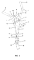
- the handlebar set comprises:
- a flange 21 is attached, provided with side extensions where collapsing axes 22 of handlebar half bars 1 are arranged.
- Upper articulations 12 of rods 3 are made up of bases 23 that receive the lower ends of said half bars 1 and which are mounted swinging around said axes 22. These side extension of flange 21 keep said upper articulations 12 of rods 3 separate from the central plane of the handlebar set.
- Handle 4 is rotably mounted on the end of the bar forming upper part 2 of the power bar and is coupled to a rod 7 that runs inside said upper part 2, so that the rotation of said handle 4 implies a translation of said rod 7 in the longitudinal direction thereof.
- handle 4 extends at the bottom by means of a cylindrical section 18 that is provided with a lug 19 and which fits inside a corresponding cylindrical section 20 provided with a helical groove 21 in which said lug 19 slides.
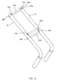
- the means for blocking the movement of collapsing handlebar half bars 1 are made up of hooks 16 arranged on each side of handle 4 and respective rings 17 arranged on said half bars 1, so that in the unfolded position of the handlebar set ( Fig. 1 ) hooks 16 engage firmly with rings 17, and they are released when handle 4 turns.
- the lower end of rod 7 is provided with a fork 15 that is mounted astride a foot 14, swinging with respect to an axis that is arranged on said foot 14 and which constitutes said collapsing axis 10 of upper part 2 of the power bar.
- This foot 14 is joined to a support plate 13 which in turn is integral with the upper end of lower part 9 of the power bar.
- the means for blocking the collapsing movement of upper part 2 of the power bar with respect to lower part 9 thereof are made up of the lower end of rod 7 and a hole 8 that is provided on the upper part of foot 14 and in which said rod 7 is inserted.
- a hole 8 that is provided on the upper part of foot 14 and in which said rod 7 is inserted.
- housings 24 are provided for the lower articulations 11 of rods 3, so that said lower articulations 11 are closer to the front of the bicycle than collapsing axis 10.
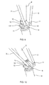
- the system according to the invention operates as described below.
- the user collapses upper part 2 of the power bar backwards.
- the user can advantageously use actual handle 4 to hold the handlebar set and fold and perform the folding with one hand.
- the movement of collapsing upper part 2 of the power bar automatically causes a movement of collapsing the handlebar half bars 1 towards the central plane ( Figs. 3 and 4 ), thanks to the fact that rods 3 join handlebar half bars 1 in an articulated manner to upper part 2 of the power bar.
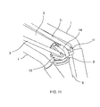
- FIG. 5 shows with greater clarity how rods 3 work.
- lower articulation 11 of rod 3 is closer to the front of the bicycle than collapsing axis 10 of upper part 2 of the power bar. Due to this offset position, and since rods 3 are rigid, when upper part 2 of the power bar is collapsed backwards the distance between upper articulation 12 of each handlebar half bar 1 and collapsing axis 10 of said upper part 2 of the power bar is shortened, and this shortening can only occur by collapsing the handlebar half bars 1 towards the central plane.
- Point P1 shown in Fig. 5 shows the virtual position of upper articulation 12 which would correspond to the raised position. As can be seen, the position of upper articulation 12 in the collapsed position is closer to collapsing axis 10 than point P1.
- rods 3 establish a biyective relationship between the collapsed position of upper part 2 of the power bar and the collapsed position of the handlebar half bars 1.
- the manoeuvre for unfolding the handlebar set is carried out in reverse order to the folding manoeuvre and with the same ease: to move from the folded position ( Fig. 4 ) to the position of use ( Fig .1 ), the user only needs to raise upper part 2 of the power bar to its raised position, this way causing at the same time the unfolding of the handlebar half bars 1.
- the user can help himself advantageously by using handle 4 to carry out the operation comfortably with just one hand.
- hooks 16 are engaged with rings17, therefore blocking the collapsing of half bars 1, and the lower end of rod 7 is inserted in hole 8, thereby blocking the collapsing of upper part 2 of the power bar.
- the manoeuvre for folding the handlebar set consists in collapsing said set backwards, with respect to a rotation axis perpendicular to the central plane of the handlebar set, which implies automatically collapsing, towards said central plane, the two half bars 1a forming the handlebar bar.
- This central plane of the handlebar set coincides with the central plane of the bicycle when the front wheel is arranged on said central plane of the handlebar set.
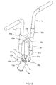
- the handlebar set comprises:
- the handlebar half bars 1 a are inserted into respective blind, cylindrical bushings 31 a arranged on the ends of lower transverse bar 19a which, in turn, is joined to lower part 9a of the power bar.
- a through transverse groove 21 a is formed, in which a lug 22a, forming the end of said lower transverse bar 19a, is inserted.
- Each transverse groove 21 a extends in a circular arch of approximately three quarter circumference, in a plane perpendicular to the axis of handlebar half bar 1 a, and lug 22a is sized so that it passes through said handlebar half bar 1a via said transverse groove 21 a.
- the axis of lower transverse bar 19a thus forms a second collapsing axis 20a, perpendicular to the central plane of the handlebar set and arranged in an offset position with respect to the first collapsing axis 10a, around which the two handlebar half bars 1a can swing.
- each of these handlebar half bars 1a can rotate around its own longitudinal axis, thanks to the fact that lug 22a can slide along transverse groove 21 a.
- the handlebar half bars 1 a are inserted into respective open, cylindrical bushings 30a, with respect to which they can slide in the longitudinal direction.
- Bushings 30a are arranged at the ends of upper transverse bar 23a, with which the end of upper part 2a of the power bar is integral.
- a through helical groove 24a is formed, in which a lug 25a, forming the end of upper transverse bar 23a, is inserted.
- Helical groove 24a is made up of two sections on one and the other side of the handlebar half bar 1 a, so that lug 25a passes through said handlebar half bar 1 a via said helical groove 24a and can slide along it.
- handlebar half bars 1a swing with respect to the second collapsing axis 20a. Due to the offset position of both collapsing axes 10a, 20a, lugs 25a move with respect to handlebar half bars 1 a in the longitudinal direction thereof.
- Fig. 15 which corresponds to the collapsed position, shows in dotted lines the location of upper transverse bar 23a that corresponds to the raised position in Fig. 12 . Since lugs 25a are guided in helical grooves 24a, their movement in the longitudinal direction of the handlebar half bars 1a causes said half bars to rotate around their own longitudinal axis.
- the handlebar set also comprises means for blocking the collapsing movement of upper part 2a of the power bar at least in the raised position and in the collapsed position.
- These blocking means are made up of a circular, sliding surface 27a formed in lower part 9a of the power bar, provided with respective orifices 28a, 29a, and a bolt (not shown in the drawings) that emerges from the lower end of upper part 2a of the power bar, so that it is facing said sliding surface 27a.
- the bolt is urged permanently by a spring towards its exit position.
- a handle 26a is mounted which is activated by pulling it towards said upper transverse bar 23a.
- Handle 26a is activated against the force of said spring that urges the bolt permanently and this implies a movement of withdrawing said bolt from orifice 28a or 29a, thereby unblocking the collapsing movement of upper part 2a of the power bar.
Landscapes
- Engineering & Computer Science (AREA)
- Mechanical Engineering (AREA)
- Steering Devices For Bicycles And Motorcycles (AREA)
- Motorcycle And Bicycle Frame (AREA)
Applications Claiming Priority (3)
| Application Number | Priority Date | Filing Date | Title |
|---|---|---|---|
| ES201131213A ES2368393B1 (es) | 2011-07-15 | 2011-07-15 | Conjunto de manillar de bicicleta. |
| ES201230293 | 2012-02-27 | ||
| PCT/ES2012/070531 WO2013011181A2 (es) | 2011-07-15 | 2012-07-12 | Conjunto de manillar de bicicleta |
Publications (1)
| Publication Number | Publication Date |
|---|---|
| EP2733057A2 true EP2733057A2 (de) | 2014-05-21 |
Family
ID=46852046
Family Applications (1)
| Application Number | Title | Priority Date | Filing Date |
|---|---|---|---|
| EP12759493.5A Withdrawn EP2733057A2 (de) | 2011-07-15 | 2012-07-12 | Fahrradlenkeranordnung |
Country Status (4)
| Country | Link |
|---|---|
| US (1) | US20140165773A1 (de) |
| EP (1) | EP2733057A2 (de) |
| CN (1) | CN103813956A (de) |
| WO (1) | WO2013011181A2 (de) |
Cited By (2)
| Publication number | Priority date | Publication date | Assignee | Title |
|---|---|---|---|---|
| CN108025787A (zh) * | 2014-09-18 | 2018-05-11 | 高永承 | 折叠式滑板车 |
| FR3106809A1 (fr) * | 2020-02-03 | 2021-08-06 | MyLuluBike | Bicyclette à guidon repliable |
Families Citing this family (11)
| Publication number | Priority date | Publication date | Assignee | Title |
|---|---|---|---|---|
| JP2016034797A (ja) * | 2014-08-02 | 2016-03-17 | 株式会社マルイ | ハンドル構造 |
| US9815515B2 (en) * | 2014-08-02 | 2017-11-14 | Shinji Marui | Steering apparatus with forward extended fork legs |
| CN104590460B (zh) * | 2015-01-09 | 2016-10-19 | 太仓市车中宝休闲用品有限公司 | 快捷锁接式v字形折叠手把 |
| CN104627305A (zh) * | 2015-01-28 | 2015-05-20 | 天津美瑞自行车有限公司 | 一种自行车折叠车把 |
| CN105460149A (zh) * | 2015-12-28 | 2016-04-06 | 宁波大胜日用制品有限公司 | 一种带有连杆式折叠车把的滑板车 |
| CN106956735A (zh) * | 2017-04-20 | 2017-07-18 | 深圳市永杰诚实业有限公司 | 一种手柄电动折叠滑板车 |
| DE102018121234A1 (de) * | 2018-08-30 | 2020-03-05 | Joachim Lohr | Verstellbarer Lenker für ein Fahrzeug |
| EP3686100A1 (de) * | 2019-01-22 | 2020-07-29 | Azure Bike International Ltd. | Zusammenklappbarer lenker eines fahrrads |
| CN110001852A (zh) * | 2019-04-19 | 2019-07-12 | 无锡圣达车业科技有限公司 | 一种折叠手把立管结构 |
| CN110723250B (zh) * | 2019-10-29 | 2021-02-26 | 腾讯科技(深圳)有限公司 | 转向控制装置 |
| CN110789654B (zh) * | 2019-11-25 | 2021-03-23 | 腾讯科技(深圳)有限公司 | 车把及车 |
Family Cites Families (14)
| Publication number | Priority date | Publication date | Assignee | Title |
|---|---|---|---|---|
| DE2967021D1 (en) | 1979-10-03 | 1984-07-05 | Brompton Bicycle Ltd | Folding bicycle |
| EP0197163A1 (de) * | 1985-04-01 | 1986-10-15 | QUASAR S.r.l. | Zusammenklappbares Fahrzeug, insbesondere ein zweirädriges |
| US5887882A (en) * | 1995-05-26 | 1999-03-30 | Atchison; James P. | Prone bicycle |
| JP2000309293A (ja) * | 1999-02-26 | 2000-11-07 | Kusuki Seisakusho:Kk | 省スペース型自転車用ハンドル |
| DE10031853A1 (de) * | 2000-07-04 | 2002-01-17 | Metallwarenfab Humpert W Gmbh | Faltbarer Fahrradlenker |
| PL1638835T3 (pl) | 2003-06-12 | 2008-10-31 | Studio Moderna Sa | Rower składany |
| FR2861048B1 (fr) * | 2003-10-15 | 2007-02-09 | Bied Dominique | Bicyclette pliable et procede de pliage |
| GB2429440B (en) | 2005-08-25 | 2009-04-22 | Jonathan Hudson | A Bicycle Having a Stem |
| CN200988550Y (zh) * | 2006-06-30 | 2007-12-12 | 庞明方 | 折叠架 |
| CN201105790Y (zh) | 2007-11-08 | 2008-08-27 | 徐达来 | 自行车折叠车把 |
| TW201029876A (en) | 2009-02-13 | 2010-08-16 | Giant Mfg Co Ltd | Bike folding mechanism |
| CN201534596U (zh) | 2009-09-08 | 2010-07-28 | 来剑波 | 折合式车把 |
| CN201545127U (zh) | 2009-09-08 | 2010-08-11 | 来剑波 | 便携箱式电动自行车 |
| CN201784764U (zh) | 2010-08-27 | 2011-04-06 | 大行科技(深圳)有限公司 | 自行车折叠定位装置 |
-
2012
- 2012-07-12 EP EP12759493.5A patent/EP2733057A2/de not_active Withdrawn
- 2012-07-12 US US14/232,668 patent/US20140165773A1/en not_active Abandoned
- 2012-07-12 WO PCT/ES2012/070531 patent/WO2013011181A2/es not_active Ceased
- 2012-07-12 CN CN201280044889.2A patent/CN103813956A/zh active Pending
Non-Patent Citations (1)
| Title |
|---|
| See references of WO2013011181A2 * |
Cited By (3)
| Publication number | Priority date | Publication date | Assignee | Title |
|---|---|---|---|---|
| CN108025787A (zh) * | 2014-09-18 | 2018-05-11 | 高永承 | 折叠式滑板车 |
| FR3106809A1 (fr) * | 2020-02-03 | 2021-08-06 | MyLuluBike | Bicyclette à guidon repliable |
| WO2021156286A1 (fr) * | 2020-02-03 | 2021-08-12 | MyLuluBike | Vehicule a deux roues a guidon repliable |
Also Published As
| Publication number | Publication date |
|---|---|
| CN103813956A (zh) | 2014-05-21 |
| US20140165773A1 (en) | 2014-06-19 |
| WO2013011181A2 (es) | 2013-01-24 |
| WO2013011181A3 (es) | 2013-03-07 |
Similar Documents
| Publication | Publication Date | Title |
|---|---|---|
| EP2733057A2 (de) | Fahrradlenkeranordnung | |
| RU128174U1 (ru) | Транспортное средство с поворотным колесом | |
| US8844960B2 (en) | Foldable tricycle | |
| US9580131B1 (en) | Foldable child's tricycle and folding method thereof | |
| EP2946985B1 (de) | Kinderwagen | |
| EP1466810B1 (de) | Schiebewagen | |
| US10214262B2 (en) | Collapsible kick-scooter vehicle | |
| EP2368784A1 (de) | Klappbarer Kinderwagen | |
| WO2013122461A1 (en) | Foldable scooter | |
| EP3015352B1 (de) | Lastenfahrrad | |
| CN106032159A (zh) | 一种具有可折叠转向方向杆的代步车辆 | |
| CN205707075U (zh) | 一种方向杆可伸缩的代步车辆 | |
| EP1927539A2 (de) | Klappbares Fahrrad | |
| CN109050761B (zh) | 手拉折叠的滑板车 | |
| CN201362286Y (zh) | 一种可折叠的儿童推车 | |
| CN221090839U (zh) | 一种推车转向机构 | |
| EP3733477B1 (de) | Faltbarer rahmen für einen einkaufswagen | |
| US20190291807A1 (en) | Foldable cycle assembly | |
| CN205589389U (zh) | 一种新型滑板车折叠机构 | |
| WO2011141698A1 (en) | Collapsible support frame | |
| CN205554279U (zh) | 可折叠婴儿车 | |
| CN115946801B (zh) | 一种独轮自行车 | |
| CN222247504U (zh) | 三轮滑步车 | |
| KR101767217B1 (ko) | 길이 조절 및 분리 가능한 핸들을 갖는 자전거 | |
| GB2480278A (en) | A collapsible support frame for carrying a load |
Legal Events
| Date | Code | Title | Description |
|---|---|---|---|
| PUAI | Public reference made under article 153(3) epc to a published international application that has entered the european phase |
Free format text: ORIGINAL CODE: 0009012 |
|
| 17P | Request for examination filed |
Effective date: 20140213 |
|
| AK | Designated contracting states |
Kind code of ref document: A2 Designated state(s): AL AT BE BG CH CY CZ DE DK EE ES FI FR GB GR HR HU IE IS IT LI LT LU LV MC MK MT NL NO PL PT RO RS SE SI SK SM TR |
|
| DAX | Request for extension of the european patent (deleted) | ||
| STAA | Information on the status of an ep patent application or granted ep patent |
Free format text: STATUS: THE APPLICATION IS DEEMED TO BE WITHDRAWN |
|
| 18D | Application deemed to be withdrawn |
Effective date: 20160202 |