EP2733083A2 - Cageots et machine de montage de cageots - Google Patents
Cageots et machine de montage de cageots Download PDFInfo
- Publication number
- EP2733083A2 EP2733083A2 EP13191099.4A EP13191099A EP2733083A2 EP 2733083 A2 EP2733083 A2 EP 2733083A2 EP 13191099 A EP13191099 A EP 13191099A EP 2733083 A2 EP2733083 A2 EP 2733083A2
- Authority
- EP
- European Patent Office
- Prior art keywords
- cardboard
- wall
- carton
- layer
- paperboard
- Prior art date
- Legal status (The legal status is an assumption and is not a legal conclusion. Google has not performed a legal analysis and makes no representation as to the accuracy of the status listed.)
- Granted
Links
Images


Classifications
-
- B—PERFORMING OPERATIONS; TRANSPORTING
- B65—CONVEYING; PACKING; STORING; HANDLING THIN OR FILAMENTARY MATERIAL
- B65D—CONTAINERS FOR STORAGE OR TRANSPORT OF ARTICLES OR MATERIALS, e.g. BAGS, BARRELS, BOTTLES, BOXES, CANS, CARTONS, CRATES, DRUMS, JARS, TANKS, HOPPERS, FORWARDING CONTAINERS; ACCESSORIES, CLOSURES, OR FITTINGS THEREFOR; PACKAGING ELEMENTS; PACKAGES
- B65D5/00—Rigid or semi-rigid containers of polygonal cross-section, e.g. boxes, cartons or trays, formed by folding or erecting one or more blanks made of paper
- B65D5/001—Rigid or semi-rigid containers of polygonal cross-section, e.g. boxes, cartons or trays, formed by folding or erecting one or more blanks made of paper stackable
- B65D5/0015—Rigid or semi-rigid containers of polygonal cross-section, e.g. boxes, cartons or trays, formed by folding or erecting one or more blanks made of paper stackable the container being formed by folding up portions connected to a central panel
- B65D5/003—Rigid or semi-rigid containers of polygonal cross-section, e.g. boxes, cartons or trays, formed by folding or erecting one or more blanks made of paper stackable the container being formed by folding up portions connected to a central panel having ledges formed by extensions of the side walls
-
- B—PERFORMING OPERATIONS; TRANSPORTING
- B65—CONVEYING; PACKING; STORING; HANDLING THIN OR FILAMENTARY MATERIAL
- B65D—CONTAINERS FOR STORAGE OR TRANSPORT OF ARTICLES OR MATERIALS, e.g. BAGS, BARRELS, BOTTLES, BOXES, CANS, CARTONS, CRATES, DRUMS, JARS, TANKS, HOPPERS, FORWARDING CONTAINERS; ACCESSORIES, CLOSURES, OR FITTINGS THEREFOR; PACKAGING ELEMENTS; PACKAGES
- B65D5/00—Rigid or semi-rigid containers of polygonal cross-section, e.g. boxes, cartons or trays, formed by folding or erecting one or more blanks made of paper
- B65D5/42—Details of containers or of foldable or erectable container blanks
- B65D5/44—Integral, inserted or attached portions forming internal or external fittings
- B65D5/441—Reinforcements
- B65D5/443—Integral reinforcements, e.g. folds, flaps
-
- B—PERFORMING OPERATIONS; TRANSPORTING
- B65—CONVEYING; PACKING; STORING; HANDLING THIN OR FILAMENTARY MATERIAL
- B65D—CONTAINERS FOR STORAGE OR TRANSPORT OF ARTICLES OR MATERIALS, e.g. BAGS, BARRELS, BOTTLES, BOXES, CANS, CARTONS, CRATES, DRUMS, JARS, TANKS, HOPPERS, FORWARDING CONTAINERS; ACCESSORIES, CLOSURES, OR FITTINGS THEREFOR; PACKAGING ELEMENTS; PACKAGES
- B65D5/00—Rigid or semi-rigid containers of polygonal cross-section, e.g. boxes, cartons or trays, formed by folding or erecting one or more blanks made of paper
- B65D5/42—Details of containers or of foldable or erectable container blanks
- B65D5/44—Integral, inserted or attached portions forming internal or external fittings
- B65D5/46—Handles
- B65D5/46072—Handles integral with the container
- B65D5/4608—Handgrip holes
-
- B—PERFORMING OPERATIONS; TRANSPORTING
- B65—CONVEYING; PACKING; STORING; HANDLING THIN OR FILAMENTARY MATERIAL
- B65D—CONTAINERS FOR STORAGE OR TRANSPORT OF ARTICLES OR MATERIALS, e.g. BAGS, BARRELS, BOTTLES, BOXES, CANS, CARTONS, CRATES, DRUMS, JARS, TANKS, HOPPERS, FORWARDING CONTAINERS; ACCESSORIES, CLOSURES, OR FITTINGS THEREFOR; PACKAGING ELEMENTS; PACKAGES
- B65D5/00—Rigid or semi-rigid containers of polygonal cross-section, e.g. boxes, cartons or trays, formed by folding or erecting one or more blanks made of paper
- B65D5/42—Details of containers or of foldable or erectable container blanks
- B65D5/64—Lids
- B65D5/66—Hinged lids
- B65D5/6626—Hinged lids formed by folding extensions of a side panel of a container body formed by erecting a "cross-like" blank
- B65D5/6629—Hinged lids formed by folding extensions of a side panel of a container body formed by erecting a "cross-like" blank the lid being formed by two mating halves joined to opposite edges of the container body
Definitions
- the invention relates to a tray.
- crates are used, for example, to transport food.
- Risers are open at the top and have handles on the side.
- a transport container in which an opening in the side walls is present.
- This opening is reinforced by a tab is collapsed parallel to the side wall on which a tongue is formed.
- This tongue is pressed by the recess in the side wall.
- the hand can be engaged in the opening without the edge of the opening cutting into the palm of the hand, since the sharp edges of the recess are covered by the tongue.
- Such a construction does not allow stacking a plurality of similar objects without concentrating the weight force on the ceiling wall or the tongue protruding upward, which is undesirable.
- a folding machine which has a Vorfaltklappe. By means of this Vorfaltklappe a tab can be bent by 90 °.
- the known machine is not suitable for producing a glued three-layer reinforcement in the ceiling area.
- the invention has for its object to propose a crate, which reduces disadvantages in the prior art.
- the invention solves the problem by a tray having (a) a bottom and an edge surrounding the bottom, wherein (b) the rim has a first sidewall, a second sidewall opposite the first sidewall, a sidewall having the second sidewall connecting first transverse wall and one of the first transverse wall opposite the second transverse wall and having the bottom forms an upwardly open trough, wherein the side walls each have an inner wall connected to the bottom and an integrally connected to the respective inner wall, extending at an angle to the inner wall ceiling wall, wherein the top wall comprises a first layer of cardboard and at least partially a second layer of cardboard.
- This tray is that the ceiling wall can be made very narrow. This in turn allows the customer to capture almost all goods at a glance.
- the reinforced ceiling wall makes it possible to provide a recess running in the ceiling wall, by means of which the crate can be gripped from above without having to grasp a side wall. This is particularly advantageous if the crate is arranged in a carton, since the crate can then be removed particularly easily.
- At least the bottom and the edge are made in one piece from a piece of cardboard.
- the entire tray is made in one piece from a cardboard box.
- connecting materials such as glue or metal staples, additionally present, but it is relevant that the production of the one piece of cardboard results in a light and stable crate at the same time.
- the ceiling walls each have (i) a top wall recess and (ii) a first cardboard layer cardboard and (iii) a second cardboard layer, the ceiling walls each having a third cardboard layer in the region of the top wall recess.
- paperboard layers are present, for example, a fourth paperboard layer.
- the crate can be made with a particularly narrow handle.
- Another advantage is that the goods received in the crate are particularly visible because they are covered only to a very small extent by the handle. This leads to the visual impression that the crate is particularly well filled, which is favorable for the presentation of goods.
- the assembly especially by means of a robot, is so simple.
- the second paperboard ply is integrally connected to the first paperboard ply by a first perforation and the first paperboard ply is integrally connected to the third paperboard ply by a second perforation. It has been found that three layers of cardboard can only be produced with low process reliability without the use of a perforation.
- the carton has an outer cardboard layer of corrugated cardboard and an inner cardboard layer of corrugated cardboard, wherein the outer cardboard layer has a greater shaft density than the inner cardboard layer.
- the shaft density is the number of waves per unit length perpendicular to the longitudinal extent of the waves.
- the shaft density in the outer paperboard layer is at least 1.5 times as large as the shaft density in the inner paperboard layer. It is particularly favorable if this shaft density in the outer cardboard layer is at least twice as large as in the inner cardboard layer. This results in a crate that is both stable and perceived as high quality. It has been found that such an appearance is unconsciously very relevant for the acceptance of the crates among the users.
- the floor extends along a floor plane and the ceiling walls each have a top wall recess which, with respect to a projection onto the floor level, has a depth of at least one centimeter has, so that the top wall laterally to the ceiling wall recess has a grip width of at least one centimeter.
- the grip width is less than three centimeters.
- the side walls each have a side wall recess, which merges into the top wall recess, wherein the side wall recess has a depth of at least one centimeter.
- this recess which is formed from the side wall recess and the Deckenwandausaus originallyung, can be particularly easy to intervene.
- the first layer of cardboard is integrally connected to the second layer of cardboard by a kink. This leads to a particularly stable ceiling wall with ease of manufacture.
- the first transverse wall has a first hinged tab and the first transverse wall has a second hinged tab, wherein the tabs can be pressed over the upwardly open trough so that they cover the trough at least predominantly, in particular at least 80%, and Support themselves on the ceiling wall, that they spring back from the position in which they cover the tub in the absence of an external force and release the tub.
- the tabs can be pressed with light pressure over the edge formed by open trough. In this condition protect the tabs the contents of the crate against an action from above. Without pressure from the outside, the ceiling walls push back the tabs so that they spring back and no longer cover the tub. The view into the tub is released.
- a packaging unit comprising a carton and at least one tray according to the invention. It is particularly favorable when the crate has a cuboid outer structure and the ground is dimensioned so that the crate can be used tightly with play in the outer carton. The game makes sense, so that the crate can be easily removed without forming a negative pressure under the crate.
- the gap between the crate and the outer carton is chosen so small that slipping of the crate relative to the carton is possible only to a small extent. For example, a gap between the crate and the inside of the outer carton is a maximum of one centimeter, in particular a maximum of 5 millimeters.
- the crates are dimensioned so that two, four or eight crates can be placed together on a floor of the carton, wherein the entirety of the crates is arranged closely adjacent to the inside of the box.
- the packaging unit has more than two trays, it is provided according to a preferred embodiment that the trays of all crates are similar in the geometric sense. This means that the aspect ratios are constant. It is particularly favorable if the areas of the bottoms of two crates are in each case integer powers of two. In other words, it is possible for a crate to be exactly half the floor area of a crate. It is then possible to arrange in a carton a crate, two crates, three and so on, which greatly facilitates the logistics when shipping food.
- the outer carton has a carton width and a carton length and has a cover flap width which corresponds to the carton width and / or whose cover flap length corresponds to the carton length, wherein the carton has a holding strip, the holding strip width at least 0.8 times the Cardboard width corresponds, which is attached to the upper side of the outer carton opposite the cover flap and which is connected to the cover flap, in particular adhesively bonded, wherein the outer carton has at least one tear thread, by means of which the cover flap can be torn open.
- the retaining strip has the advantage that the tearing is facilitated. When tearing the tearing thread exerts namely a force in the normal direction on the cover flap. Without holding tabs, this would cause the top flap to bulge upwards, giving way to the force pulling the tearing thread. This in turn makes the ripping difficult, which is undesirable.
- the retaining strip supports the cover flap at the point where the tear thread runs, so that the movement of the cover flap is reduced upwards. The cover flap can be pulled up very easily.
- the tear thread is arranged between the cover flap and the holding strip, the tear thread preferably extending in a middle third strip of the holding strip.
- the tear thread runs in the immediate vicinity of a side bisector, so that the tear thread is the same distance from the free end of the retaining strip as the edge to which the retaining strip is connected to the side wall.
- the cover flap is unattenuated, in particular unperforated, at least on its outwardly facing upper side, at least in an environment of the tear-open thread.
- the surface of the cover flap is homogeneous in other words, so that any existing perforation can not be seen from the outside. It has heretofore been assumed that a tear thread in cardboard can only be handled with perforation, but it has been established that this assumption is unfounded.
- the cover flap has at least one handle structure which is applied through a perforation and / or a recess in the cover flap, wherein the handle structure is connected to the tear thread, so that the cover flap can be opened by grasping and moving the handle structure by means of the tear thread.
- the advantage of the handle structure is that for gripping a larger area is available than the mere tear thread. It can then be applied to the handle structure a significantly lower pressure in order to move the tear thread with a sufficiently large force can, as if the tear thread would be used directly.
- the cover flap is integrally connected to the first transverse wall and the retaining strip is integrally connected to the second transverse wall.
- the tray is integrally formed, easy to manufacture and also has a high strength.
- a crate with tabs is inserted into the outer carton such that the tabs cover the trough when the outer carton is closed. If the carton is opened, usually by the customer, or if it takes another tray, the tabs are no longer held in place, quickly back and reveal the view of the contents of the crate. This allows a particularly fast unpacking of the packaging unit.
- the packaging unit comprises an insulating box, which has a base body and an insulating cover and dry ice, which emits gaseous carbon dioxide into the body, wherein the dimensions of the insulating box are chosen so that the insulating box is inserted into the outer carton, that they with game tight against the inside of the carton.
- the insulating box is dimensioned so that the outer carton, especially the cover flap, the insulating lid presses so strong against the body, that the insulating lid of the gaseous carbon dioxide can not be raised so much that it slips from the body.
- the carbon dioxide escapes at so through a thin gap between insulating cover and body.
- the insulating box has at least one vent opening through which gaseous carbon dioxide can escape.
- the insulating cover has in a side facing away from the base body particularly a depression, in particular a respective depression on two opposite edges.
- This depression preferably merges into a side surface of the insulating cover, so that the cover can be removed by engaging in the lowering without the side wall having to be touched. This allows easy removal of the insulating cover, when the insulating box is inserted into the carton.
- the insulating box is preferably formed so that there is a circumferential gap of at most 0.5 centimeters between the outer walls of the insulating box and the inside of the outer carton. Without the recess, the outer carton would first have to be pushed aside to be able to remove the lid.
- all edges of the recess have an edge radius of at least three millimeters. It has been found that such a sink is much less susceptible to contamination.
- the invention also solves the problem by a ladder erecting machine adapted to produce a tray of the invention comprising a carton having (a) a gluing device arranged to glue the carton along a first crease line at least substantially parallel to a side wall.
- a first buckling device which is designed to buckle the cardboard along the first bend line, so that in the region of a first handle (148.1) in the cardboard a first cardboard layer and a second cardboard layer are formed
- a second buckling device configured to buckle the carton along a second crease line that is at least substantially parallel to the first crease line such that a third paperboard ply results in the region of the handle
- a pusher device configured to press the cardboard layers, so that the three layers of cardboard under pressure mitein are glued together.
- the gluing device is preferably arranged for gluing the cardboard along the second crease line which runs at least substantially parallel to the first crease line.
- the gluing device emits at least two glue points adjacent to the second bending line. Conveniently, a continuous or interrupted glue strips.
- the crate-erecting machine has a U-shaped derailleur, which is designed to engage in a recess in the carton. This recess exposes the handle.
- This derailleur can preferably be designed so that it allows the buckling of the third paperboard layer by only one movement. It can be at this movement act a translational movement, a tilting movement or a combined movement.
- the U-shaped front derailleur has a flank which is arranged so that the third cardboard layer is overturned during the movement of the front derailleur by means of the flank and thus bent.
- the derailleur is arranged to the pressing device, that the printing device presses the derailleur during bonding to the carton.
- the pressing device presses the first paperboard ply and the second paperboard ply directly against one another, whereas it presses the third paperboard ply over the derailleur onto at least one of the two other paperboard plies.
- FIG. 1 shows a tray 10 according to the invention in a carton 12, which together form part of a packaging unit 14 according to the invention.
- the tray 12 seats a bottom 16 and a peripheral edge 18 surrounding the bottom.
- the rim 18 has a first sidewall 20, a second sidewall 22 opposite the first sidewall, a first transverse wall 24 and a second transverse wall 26.
- the rim 18 forms with the bottom 16 an upwardly open trough 19th
- the bottom 16 extends along a bottom plane E 16 , which corresponds to the paper plane in the present case.
- the first side wall 20 comprises a first ceiling wall 28, the second transverse wall 26 a second ceiling wall 30.
- the ceiling walls 28, 30 extend parallel to the ground plane E 16th
- the first ceiling wall 28 comprises a first layer of cardboard 32.1 and a second layer of cardboard 34.1 which are in FIG. 1 is covered by the first layer 32.1.
- the first ceiling wall 28 also has a ceiling wall recess 36.1.
- the second ceiling wall 30 is mirror-symmetrical to a mirror plane which is perpendicular to the ground plane E 16 , constructed to the first ceiling wall 28 and has a first layer 32.2 and a second layer 34.2 and a top wall recess 36.2.
- the first layers 32 (reference numerals without counting suffix designate the object as such) pass through a respective kink 38 into the second layer 34. It is advantageous if the two layers are glued together, so that there is a higher strength.
- the ceiling wall recess 36 has a depth T 36 of 20 millimeters with respect to a projection on the ground plane E 16 .
- a ceiling wall width B is preferably between 20, in particular 40, and 80 millimeters and in the present case is 70 millimeters.
- the depth of the DeckenwandAusappelung is at least 0.3 times, in particular 0.4 times a width B of the ceiling walls 28, 30th
- the first side wall 20 has a side wall recess 40.1, which merges with the top wall recess 36.1 and forms a common recess.
- a depth of T 40 is 25 millimeters.
- a gap S 26 between the second transverse wall 26 and the outer carton and a gap S 24 between the first transverse wall 24 and the outer carton each is less than three times a carton thickness of the carton from which the tray 10 is constructed.
- a gap S 20 between the first side wall and the outer carton and a gap S 22 between the second side wall 22 and the outer carton are each smaller than twice the thickness of the carton.
- FIG. 2a shows the outer carton 12, which has a carton width B 12 and a carton length L 12 .
- the outer carton 12 comprises a cover flap 42 having a cover flap width B 42 , which corresponds to the carton width B 12 .
- the cover flap length L 42 corresponds to the outer carton length L 12 .
- the outer carton 12 also has a holding strip 44, the holding strip width B 44 also corresponds to the carton width B 12 .
- FIG. 2a shows the state in which the cover flap 42 is separated from the retaining strip 44. Therefore, the holding strip 44 has a tear-open edge 46.1 and the cover flap 42 has a tear-open edge 46.2 which has been created by the tearing open.
- FIG. 2b shows the cover flap 42 and the retaining strip 44 before tearing, that is, a tearing edge does not exist yet. It can be seen that the cover flap 42 has a handle structure 48 which is created by a recess 50 and a subsequent perforation 52 in the cover flap 42 so that it can be detached by grasping by hand from the cover flap 42.
- a tear thread 54 is fixed, which in FIG. 2b is covered by the cover flap 42 and therefore shown in dashed lines.
- the tear thread 50 can be pulled through the cover flap 42, so that it along the tear edges 46 (see. FIG. 2a ) is separated.
- the retaining strip 44 is thus always arranged below the recess 50, so that despite the recess 50 no access to the interior of the outer carton 12 is possible.
- FIG. 3 shows a packaging unit 14, which includes an insulating box 56, which is inserted tightly with play in the outer carton 12.
- the insulating box 56 has an insulating cover 58, which is like a in FIG. 3 non-visible body of the insulating box 56 made of foamed polystyrene.
- the insulating cover 58 has two depressions 60.1, 60.2 in its upper side, which propagate into the sides of the insulating cover 58. It is thus possible to easily remove the insulating cover 58 by engaging in the depressions 60. All edges of the recess 60 have an edge radius r, which is at least three millimeters. The in FIG. 3 drawn edge radius r is 10 millimeters.
- FIG. 4 shows a tray 10 and an insulating box 56, which can be used together in a cardboard not shown 12. It can be seen that they have the same outer dimensions, so that instead of the insulating box 56, a second tray 10 could be inserted into the outer carton.
- packaging unit still belongs a third tray, the bottom of which has twice the area of the bottoms of the crate 10 and the insulating box 56 so that it can be placed flush on the crate 10 and the insulating box 56. It is therefore possible to arrange this third tray above or below the tray 10 and the insulating box 56 in a carton.
- FIG. 5 shows in the partial figure 5a a carton blank, from which a further tray 10 according to the invention is produced.
- the subfigures 5b, 5c and 5d show the folding process.
- the first transverse wall 24 has a first tab 62.
- the second transverse wall 26 has a second tab 64.
- the tabs 62, 64 each have a handle hole is arranged so that each of the tabs can be grasped by hand.
- Subfigure 5e shows that the two tabs 62, 64 cover the trough 19 formed by the edge 18 upwards, for example when a force is exerted on the tabs 62, 64 with a finger 66.
- the tabs 62, 64 overlap so that a force on one of the tabs, in the present case on the second tab 64, is sufficient to hold both tabs 62, 64 so that the trough 19 is covered upwards. If the force is released, for example by the fact that in FIG. 5 the finger is removed, press the ceiling walls 28, 30, the tabs in a position in which the trough 19 is no longer covered. This situation is shown in subfigure 5d.
- FIG. 6 shows a tray 110 according to the invention according to another embodiment in a outer carton 112, which together form part of a packaging unit 114 according to the invention.
- the tray 112 has a bottom 116 and a peripheral rim 118.
- the rim 118 has a first sidewall 120, a second sidewall 122 opposite the first sidewall, a first transverse wall 124 and a second transverse wall 126.
- the rim 118 forms with the bottom 116 an upwardly open trough 119th
- the floor 116 extends along a floor level E 116 , which in the present case corresponds to the paper level.
- the first side wall 120 comprises a first ceiling wall 128, the second side wall 122 a second ceiling wall 130.
- the ceiling walls 128, 130 extend parallel to the floor level E 116 .
- the first ceiling wall 128 comprises a first layer of cardboard 132.1 and a second layer of cardboard 134.1 (see FIG Figure 7a ), in the FIG. 6 is covered by the first layer 132.1.
- the first ceiling wall 128 also has a Deckenwandaus strictlyung 136.
- the second ceiling wall 130 is mirror-symmetrical to a mirror plane which is perpendicular to the ground plane E 116 , constructed to the first ceiling wall 128 and has a first layer 132.2 and a second layer 134.2 and a ceiling wall recess 136.2.
- the first layers 132 pass through a respective kink 138.1, 138.2 into the second layer 134. It is advantageous if the two layers 132, 134 are glued together, resulting in a higher strength.
- the ceiling wall recess 136 has a depth T 136 of 20 millimeters with respect to a projection on the ground plane E 116 .
- a ceiling wall width B1 is preferably between 20, in particular 40, and 80 millimeters and is in the present case 70 millimeters.
- the depth of the DeckenwandAusappelung is at least 0.3 times, in particular 0.4 times a width of the ceiling wall.
- first side wall 20 has a side wall recess 140.1, which merges with the top wall recess 136.1 and forms a common recess.
- a depth T 140 is 25 millimeters.
- FIG. 6 shows that the crate 110 fits snugly, but with play, on an inner side of the outer carton 112.
- a gap S 126 between the second transverse wall 126 and the outer carton 112 and a gap S 124 between the first transverse wall 124 and the outer carton 112, respectively, is less than three times a carton thickness of the carton from which the tray 110 is constructed.
- a gap S 120 between the first side wall and the outer carton 112 and a gap S 122 between the second side wall 122 and the outer carton 112 are each smaller than twice the thickness of the carton.
- the ceiling walls 128, 130 in the region of the cover wall recess 136 have a third layer 142 on cardboard, that is to say a third cardboard layer.
- This third paperboard layer 142 is formed by a tab which protrudes into the Deckenwandaus Principleung 136 before.
- the third cardboard layer 142 is shown in dashed lines, as they in the view FIG. 6 is covered.
- Figure 7a shows a perspective view of the tray 110. It can be seen that the first paperboard layer 132.1 is connected to the second paperboard layer 134.1 by a perforation 144.1. The second paperboard layer 134.1 is connected to the third paperboard layer 142.1 by a second perforation 146.1 which is in line with the first perforation 144.1. The third cardboard layer 142.1 is formed only in the region of the cover wall recess 136.1.
- Both the first perforation 144.1 and the second perforation 146.1 each comprise two non-drawn perforation lines, which run at a distance which is greater than a cardboard thickness of the carton. Therefore, two buckling areas extending adjacent to one another form during buckling, in which the cardboard is bent by about 90 ° in each case. In this way, the force acting on the adhesive bond between the paperboard layers is small, which ensures high stability.
- the first paperboard ply 132.1 forms the first ceiling wall 128.
- the second paperboard ply 134.1 has a width B 134 substantially equal to a difference between the width B 128 of the first ceiling wall 128 and the depth T 136 (see FIG FIG. 7b ) corresponds to the ceiling wall recess 136.
- the second cardboard layer 134.1 is as wide as possible, so that the handle, which is formed by the three cardboard layers 132.1, 134.1, 142.1 in the region of the cover wall recess 136.1, is as stable as possible.
- the width B 134 of the second paperboard layer 134.1 is as large as possible.
- the width B 142 of the third layer 142.1 corresponds to the width B 134 of the second paperboard layer 134.1.
- the two widths B 142 and B 134 correspond to each other, it means that they should be as similar as possible to each other. In particular, it is favorable if the widths B 142 , B 134 deviate from one another by at most 20%.
- FIG. 7b shows the cardboard layers 132.2, 134.2, 142.2 in the assembled assembly. It can be seen that a handle width B 148 of a handle 148 corresponds substantially to half the width B of the top wall 128. In particular, the handle width B 148 deviates by a maximum of 20% from half the width B of the top wall 128.
- FIG. 8 shows a ramp erector 150 according to the invention for manufacturing a tray 110 described above, which is located in the unfolded state.
- the tray erecting machine 150 has a gluing device 152, which consists of two parts, wherein only the first part of the gluing device, which is designated by the reference numeral 152.1, is schematically drawn.
- This gluing device 152 is arranged to glue the box 154, from which the crate 110 is made by folding.
- the gluing device 152 glues the cardboard 154 along a first crease line 138 in which the kink 138 extends after kinking.
- the glueing device 152.1 applies a glue trace 156.1, which is shown schematically.
- the tray erector 150 includes a first buckling device 158 that includes a pivotally mounted buckling block 160.
- a first buckling device 158 that includes a pivotally mounted buckling block 160.
- the gluing device 152 is also designed to glue the cardboard 154 along a second crease line 162, which runs parallel to the first crease line 138.
- the tray erector 154 has a second buckling device 164 with a derailleur 166.1.
- the derailleur 166.1 is arranged so that it engages in operation in the Deckenwandausappelung 136.1 and a tab 168.1, which projects into the Deckenwandausappelung 136 and is connected via the second crease line 162 with the rest of the box 154 in conjunction, kinks along the second crease line 162.
- the derailleur 166 performs a tilting movement, which schematically in FIG. 9 is shown.
- the platform erector 150 also has a second derailleur which is arranged symmetrically and in FIG. 8 can not be seen, and a pushing device 170 which is arranged to the first buckling device 158 and the second buckling device 164 so that it presses on the derailleur 166 on the one hand and on the second cardboard layer 134 when activated.
- first two cardboard layers 132, 134 are pressed against each other by direct contact with the pressing device, the first and third paperboard layers 132.1, 42.1 or the second paperboard layer 134.1 and the third paperboard layer 142.1 are pressed over one another via the front derailleur 166 , In this way, all cardboard layers can be pressed against each other by means of the pressing device 170, wherein only a movement of the printing device 170 is necessary for exerting this pressure.
- the ladder erector 150 has symmetrically constructed devices for analog processing of the right side of the crate. The processing is synchronous.
- FIG. 9 schematically shows the function of the derailleur 166.
- a tab 168 which projects into the top wall recess 136, along the perforation 146.1 kinked and so the third layer 142.1 produced on cardboard.
- the derailleur 166 engages in a recess 178 in the box 154.
- This recess corresponds to the ceiling wall recess 136.1 (see Figure 7a ).
- Particularly favorable are two derailleurs, wherein the second derailleur engages in a second recess, the ceiling wall recess 136.1 (see Figure 7a ) corresponds.
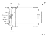
- FIG. 10 shows a view of a tray according to the invention according to a preferred embodiment. It can be seen that the second layer 134.1 as a tab is trained.
- the perforation 144.1 which is a preferred embodiment and is transferable to other embodiments, comprises two perforation lines having different perforation pitches. This means that the distances between two slots and / or the width of the slots vary.
- the second perforation 146.1 may be constructed by two perforation lines having different perforation pitches.
- a slot 174.1.1 is formed between the carrier tab 172.1.1, by means of which the first ceiling wall 128 is connected to the first transverse wall 124.
- a slot 174.1.2 is formed between the carrier tab 172.1.2, by means of which the first ceiling wall 128 is connected to the second transverse wall 126.
- the presence of the slot is a preferred embodiment and is transferable to other embodiments. These slots facilitate the erection of the crates and allow higher folding speeds. Also serves to achieve higher folding speeds that the tabs 172 taper.
- the tray 110 is, like the other embodiments also, constructed symmetrically.
- Isolierkiste 58 insulating cover 150 Steigenaufrichtmaschine 60 depression 152 gluing device 62 first tab 154 carton 64 second tab
Landscapes
- Engineering & Computer Science (AREA)
- Mechanical Engineering (AREA)
- Cartons (AREA)
- Rigid Containers With Two Or More Constituent Elements (AREA)
Priority Applications (1)
| Application Number | Priority Date | Filing Date | Title |
|---|---|---|---|
| PL13191099T PL2733083T3 (pl) | 2012-11-16 | 2013-10-31 | Opakowanie typu platonik |
Applications Claiming Priority (2)
| Application Number | Priority Date | Filing Date | Title |
|---|---|---|---|
| DE201220011408 DE202012011408U1 (de) | 2012-11-16 | 2012-11-16 | Steige und zugeordnete Verpackungseinheit |
| DE201310002749 DE102013002749A1 (de) | 2013-02-19 | 2013-02-19 | Steige, Verpackungseinheit und Steigenaufrichtmaschine |
Publications (3)
| Publication Number | Publication Date |
|---|---|
| EP2733083A2 true EP2733083A2 (fr) | 2014-05-21 |
| EP2733083A3 EP2733083A3 (fr) | 2014-08-13 |
| EP2733083B1 EP2733083B1 (fr) | 2016-08-24 |
Family
ID=49510051
Family Applications (1)
| Application Number | Title | Priority Date | Filing Date |
|---|---|---|---|
| EP13191099.4A Active EP2733083B1 (fr) | 2012-11-16 | 2013-10-31 | Cageot |
Country Status (5)
| Country | Link |
|---|---|
| EP (1) | EP2733083B1 (fr) |
| DK (1) | DK2733083T3 (fr) |
| ES (1) | ES2602278T3 (fr) |
| PL (1) | PL2733083T3 (fr) |
| PT (1) | PT2733083T (fr) |
Cited By (1)
| Publication number | Priority date | Publication date | Assignee | Title |
|---|---|---|---|---|
| CN116395275A (zh) * | 2023-05-18 | 2023-07-07 | 南京林业大学 | 一种具有防盗功能的自升降式茶饼包装 |
Citations (2)
| Publication number | Priority date | Publication date | Assignee | Title |
|---|---|---|---|---|
| DE8814572U1 (de) | 1988-11-18 | 1989-02-16 | Roepke, Gustav A., 2000 Hamburg | Behälter zum Transport von Gegenständen |
| DE19636262A1 (de) | 1996-09-06 | 1998-03-12 | Ligmatech Maschb Gmbh | Faltmaschine und Verfahren zum automatischen Falten einer Faltschachtel |
Family Cites Families (5)
| Publication number | Priority date | Publication date | Assignee | Title |
|---|---|---|---|---|
| GB1440764A (en) * | 1972-10-06 | 1976-06-23 | Ashton Containers | Box and blank therefor |
| FR2252960A1 (en) * | 1973-12-03 | 1975-06-27 | Nicollet Ets Hugues | Flat box for fruit is made by folding flat sheet - and is held in assembled position by tucked-in end flaps |
| FR2363489A1 (fr) * | 1976-08-31 | 1978-03-31 | Clergeau Papeteries Leon | Dispositif d'accrochage de materiaux en feuilles et son application a la realisation de cartons d'emballage |
| DE2805690A1 (de) * | 1978-02-10 | 1979-08-16 | Woll Geb Liebe Hildegard | Steige zum transport und zur lagerung der verschiedensten gueter, z.b. obst und gemuese, fisch, kaese o.a. |
| US4946093A (en) * | 1989-09-12 | 1990-08-07 | Nekoosa Packaging Corporation | Half slotted container lid with self-locking double side panels |
-
2013
- 2013-10-31 PL PL13191099T patent/PL2733083T3/pl unknown
- 2013-10-31 EP EP13191099.4A patent/EP2733083B1/fr active Active
- 2013-10-31 ES ES13191099.4T patent/ES2602278T3/es active Active
- 2013-10-31 DK DK13191099.4T patent/DK2733083T3/en active
- 2013-10-31 PT PT131910994T patent/PT2733083T/pt unknown
Patent Citations (2)
| Publication number | Priority date | Publication date | Assignee | Title |
|---|---|---|---|---|
| DE8814572U1 (de) | 1988-11-18 | 1989-02-16 | Roepke, Gustav A., 2000 Hamburg | Behälter zum Transport von Gegenständen |
| DE19636262A1 (de) | 1996-09-06 | 1998-03-12 | Ligmatech Maschb Gmbh | Faltmaschine und Verfahren zum automatischen Falten einer Faltschachtel |
Cited By (1)
| Publication number | Priority date | Publication date | Assignee | Title |
|---|---|---|---|---|
| CN116395275A (zh) * | 2023-05-18 | 2023-07-07 | 南京林业大学 | 一种具有防盗功能的自升降式茶饼包装 |
Also Published As
| Publication number | Publication date |
|---|---|
| DK2733083T3 (en) | 2016-11-28 |
| EP2733083A3 (fr) | 2014-08-13 |
| EP2733083B1 (fr) | 2016-08-24 |
| ES2602278T3 (es) | 2017-02-20 |
| PT2733083T (pt) | 2016-11-11 |
| PL2733083T3 (pl) | 2017-08-31 |
Similar Documents
| Publication | Publication Date | Title |
|---|---|---|
| DE69215232T2 (de) | Steige mit stülpdeckel | |
| EP0519366B1 (fr) | Jeu d'éléments de construction pour la fabrication d'un emballage | |
| EP1992574B1 (fr) | Récipient de transport d'aliments chauds, en particulier pizza | |
| DE7422464U (de) | Traeger fuer eine Anzahl von Behaeltern | |
| DE3878518T2 (de) | Karton mit verbessertem griff. | |
| EP0508240A2 (fr) | Conteneur réutilisable | |
| DE69313847T2 (de) | Verpackungseinheit für blattförmige gegenstände. | |
| EP0218186B1 (fr) | Boîte en carton, carton ondulé ou similaire | |
| DE20213450U1 (de) | Systemverpackung mit Selbstbedienungsöffnung | |
| DE102013015039B4 (de) | Transport- und Präsentationsverpackung | |
| EP2733083A2 (fr) | Cageots et machine de montage de cageots | |
| DE2001499A1 (de) | Faltschachtel | |
| EP1747735B1 (fr) | Emballage | |
| EP3705413B1 (fr) | Emballage isolant | |
| EP2450288A2 (fr) | Boîte de pliage | |
| EP0394730A1 (fr) | Emballage réalisé à partir d'un flan, avec des faces larges et des faces étroites, et muni d'une doublure interne | |
| EP3020655B1 (fr) | Emballage de vente | |
| EP3578473A1 (fr) | Découpe pliable et boîte pliante pour marchandises en vrac | |
| DE202012011408U1 (de) | Steige und zugeordnete Verpackungseinheit | |
| EP1127797A2 (fr) | Configuration d'emballage | |
| DE4400129A1 (de) | Umverpackung für Briefumschläge | |
| DE2835239C2 (de) | Verkaufsbar | |
| AT502388B1 (de) | Verpackungselement | |
| DE9115841U1 (de) | Lebensmittel-Transportbehälter | |
| DE2122807B2 (de) | Behältnis zum Stapeln und Transportieren von Flaschen, Dosen u.dgl |
Legal Events
| Date | Code | Title | Description |
|---|---|---|---|
| PUAI | Public reference made under article 153(3) epc to a published international application that has entered the european phase |
Free format text: ORIGINAL CODE: 0009012 |
|
| 17P | Request for examination filed |
Effective date: 20131031 |
|
| AK | Designated contracting states |
Kind code of ref document: A2 Designated state(s): AL AT BE BG CH CY CZ DE DK EE ES FI FR GB GR HR HU IE IS IT LI LT LU LV MC MK MT NL NO PL PT RO RS SE SI SK SM TR |
|
| AX | Request for extension of the european patent |
Extension state: BA ME |
|
| PUAL | Search report despatched |
Free format text: ORIGINAL CODE: 0009013 |
|
| AK | Designated contracting states |
Kind code of ref document: A3 Designated state(s): AL AT BE BG CH CY CZ DE DK EE ES FI FR GB GR HR HU IE IS IT LI LT LU LV MC MK MT NL NO PL PT RO RS SE SI SK SM TR |
|
| AX | Request for extension of the european patent |
Extension state: BA ME |
|
| RIC1 | Information provided on ipc code assigned before grant |
Ipc: B65D 5/00 20060101ALI20140708BHEP Ipc: B65D 5/44 20060101ALI20140708BHEP Ipc: B65D 5/468 20060101ALI20140708BHEP Ipc: B65D 5/66 20060101AFI20140708BHEP |
|
| R17P | Request for examination filed (corrected) |
Effective date: 20150109 |
|
| RBV | Designated contracting states (corrected) |
Designated state(s): AL AT BE BG CH CY CZ DE DK EE ES FI FR GB GR HR HU IE IS IT LI LT LU LV MC MK MT NL NO PL PT RO RS SE SI SK SM TR |
|
| 17Q | First examination report despatched |
Effective date: 20150915 |
|
| GRAP | Despatch of communication of intention to grant a patent |
Free format text: ORIGINAL CODE: EPIDOSNIGR1 |
|
| INTG | Intention to grant announced |
Effective date: 20160404 |
|
| INTG | Intention to grant announced |
Effective date: 20160411 |
|
| GRAS | Grant fee paid |
Free format text: ORIGINAL CODE: EPIDOSNIGR3 |
|
| GRAA | (expected) grant |
Free format text: ORIGINAL CODE: 0009210 |
|
| AK | Designated contracting states |
Kind code of ref document: B1 Designated state(s): AL AT BE BG CH CY CZ DE DK EE ES FI FR GB GR HR HU IE IS IT LI LT LU LV MC MK MT NL NO PL PT RO RS SE SI SK SM TR |
|
| REG | Reference to a national code |
Ref country code: GB Ref legal event code: FG4D Free format text: NOT ENGLISH |
|
| REG | Reference to a national code |
Ref country code: CH Ref legal event code: EP |
|
| REG | Reference to a national code |
Ref country code: AT Ref legal event code: REF Ref document number: 822830 Country of ref document: AT Kind code of ref document: T Effective date: 20160915 |
|
| REG | Reference to a national code |
Ref country code: IE Ref legal event code: FG4D Free format text: LANGUAGE OF EP DOCUMENT: GERMAN |
|
| REG | Reference to a national code |
Ref country code: DE Ref legal event code: R096 Ref document number: 502013004140 Country of ref document: DE |
|
| REG | Reference to a national code |
Ref country code: DE Ref legal event code: R081 Ref document number: 502013004140 Country of ref document: DE Owner name: DELTILOG GMBH, DE Free format text: FORMER OWNER: ECOLA GMBH, 30159 HANNOVER, DE Ref country code: DE Ref legal event code: R081 Ref document number: 502013004140 Country of ref document: DE Owner name: EXTOR GMBH, DE Free format text: FORMER OWNER: ECOLA GMBH, 30159 HANNOVER, DE Ref country code: DE Ref legal event code: R081 Ref document number: 502013004140 Country of ref document: DE Owner name: DELTITRADE GMBH, DE Free format text: FORMER OWNER: ECOLA GMBH, 30159 HANNOVER, DE |
|
| REG | Reference to a national code |
Ref country code: FR Ref legal event code: PLFP Year of fee payment: 4 |
|
| RAP2 | Party data changed (patent owner data changed or rights of a patent transferred) |
Owner name: EXTOR GMBH |
|
| REG | Reference to a national code |
Ref country code: SE Ref legal event code: TRGR |
|
| REG | Reference to a national code |
Ref country code: PT Ref legal event code: SC4A Ref document number: 2733083 Country of ref document: PT Date of ref document: 20161111 Kind code of ref document: T Free format text: AVAILABILITY OF NATIONAL TRANSLATION Effective date: 20161028 |
|
| REG | Reference to a national code |
Ref country code: CH Ref legal event code: NV Representative=s name: BRAUNPAT BRAUN EDER AG, CH |
|
| REG | Reference to a national code |
Ref country code: DK Ref legal event code: T3 Effective date: 20161121 |
|
| REG | Reference to a national code |
Ref country code: NL Ref legal event code: FP |
|
| REG | Reference to a national code |
Ref country code: DE Ref legal event code: R081 Ref document number: 502013004140 Country of ref document: DE Owner name: DELTILOG GMBH, DE Free format text: FORMER OWNER: EXTOR GMBH, 30559 HANNOVER, DE Ref country code: DE Ref legal event code: R081 Ref document number: 502013004140 Country of ref document: DE Owner name: DELTITRADE GMBH, DE Free format text: FORMER OWNER: EXTOR GMBH, 30559 HANNOVER, DE Ref country code: DE Ref legal event code: R082 Ref document number: 502013004140 Country of ref document: DE Representative=s name: GRAMM, LINS & PARTNER PATENT- UND RECHTSANWAEL, DE Ref country code: DE Ref legal event code: R082 Ref document number: 502013004140 Country of ref document: DE Representative=s name: GLAWE DELFS MOLL PARTNERSCHAFT MBB VON PATENT-, DE |
|
| REG | Reference to a national code |
Ref country code: NO Ref legal event code: T2 Effective date: 20160824 Ref country code: LT Ref legal event code: MG4D |
|
| RAP2 | Party data changed (patent owner data changed or rights of a patent transferred) |
Owner name: DELTITRADE GMBH |
|
| PG25 | Lapsed in a contracting state [announced via postgrant information from national office to epo] |
Ref country code: RS Free format text: LAPSE BECAUSE OF FAILURE TO SUBMIT A TRANSLATION OF THE DESCRIPTION OR TO PAY THE FEE WITHIN THE PRESCRIBED TIME-LIMIT Effective date: 20160824 Ref country code: LT Free format text: LAPSE BECAUSE OF FAILURE TO SUBMIT A TRANSLATION OF THE DESCRIPTION OR TO PAY THE FEE WITHIN THE PRESCRIBED TIME-LIMIT Effective date: 20160824 Ref country code: HR Free format text: LAPSE BECAUSE OF FAILURE TO SUBMIT A TRANSLATION OF THE DESCRIPTION OR TO PAY THE FEE WITHIN THE PRESCRIBED TIME-LIMIT Effective date: 20160824 |
|
| REG | Reference to a national code |
Ref country code: ES Ref legal event code: FG2A Ref document number: 2602278 Country of ref document: ES Kind code of ref document: T3 Effective date: 20170220 |
|
| PG25 | Lapsed in a contracting state [announced via postgrant information from national office to epo] |
Ref country code: LV Free format text: LAPSE BECAUSE OF FAILURE TO SUBMIT A TRANSLATION OF THE DESCRIPTION OR TO PAY THE FEE WITHIN THE PRESCRIBED TIME-LIMIT Effective date: 20160824 Ref country code: GR Free format text: LAPSE BECAUSE OF FAILURE TO SUBMIT A TRANSLATION OF THE DESCRIPTION OR TO PAY THE FEE WITHIN THE PRESCRIBED TIME-LIMIT Effective date: 20161125 |
|
| PG25 | Lapsed in a contracting state [announced via postgrant information from national office to epo] |
Ref country code: EE Free format text: LAPSE BECAUSE OF FAILURE TO SUBMIT A TRANSLATION OF THE DESCRIPTION OR TO PAY THE FEE WITHIN THE PRESCRIBED TIME-LIMIT Effective date: 20160824 Ref country code: RO Free format text: LAPSE BECAUSE OF FAILURE TO SUBMIT A TRANSLATION OF THE DESCRIPTION OR TO PAY THE FEE WITHIN THE PRESCRIBED TIME-LIMIT Effective date: 20160824 |
|
| REG | Reference to a national code |
Ref country code: DE Ref legal event code: R097 Ref document number: 502013004140 Country of ref document: DE |
|
| PG25 | Lapsed in a contracting state [announced via postgrant information from national office to epo] |
Ref country code: SK Free format text: LAPSE BECAUSE OF FAILURE TO SUBMIT A TRANSLATION OF THE DESCRIPTION OR TO PAY THE FEE WITHIN THE PRESCRIBED TIME-LIMIT Effective date: 20160824 Ref country code: BG Free format text: LAPSE BECAUSE OF FAILURE TO SUBMIT A TRANSLATION OF THE DESCRIPTION OR TO PAY THE FEE WITHIN THE PRESCRIBED TIME-LIMIT Effective date: 20161124 Ref country code: SM Free format text: LAPSE BECAUSE OF FAILURE TO SUBMIT A TRANSLATION OF THE DESCRIPTION OR TO PAY THE FEE WITHIN THE PRESCRIBED TIME-LIMIT Effective date: 20160824 |
|
| PLBE | No opposition filed within time limit |
Free format text: ORIGINAL CODE: 0009261 |
|
| STAA | Information on the status of an ep patent application or granted ep patent |
Free format text: STATUS: NO OPPOSITION FILED WITHIN TIME LIMIT |
|
| REG | Reference to a national code |
Ref country code: IE Ref legal event code: MM4A |
|
| 26N | No opposition filed |
Effective date: 20170526 |
|
| PG25 | Lapsed in a contracting state [announced via postgrant information from national office to epo] |
Ref country code: SI Free format text: LAPSE BECAUSE OF FAILURE TO SUBMIT A TRANSLATION OF THE DESCRIPTION OR TO PAY THE FEE WITHIN THE PRESCRIBED TIME-LIMIT Effective date: 20160824 Ref country code: LU Free format text: LAPSE BECAUSE OF NON-PAYMENT OF DUE FEES Effective date: 20161031 |
|
| REG | Reference to a national code |
Ref country code: FR Ref legal event code: PLFP Year of fee payment: 5 |
|
| REG | Reference to a national code |
Ref country code: DE Ref legal event code: R082 Ref document number: 502013004140 Country of ref document: DE Representative=s name: GLAWE DELFS MOLL PARTNERSCHAFT MBB VON PATENT-, DE |
|
| PG25 | Lapsed in a contracting state [announced via postgrant information from national office to epo] |
Ref country code: IE Free format text: LAPSE BECAUSE OF NON-PAYMENT OF DUE FEES Effective date: 20161031 |
|
| REG | Reference to a national code |
Ref country code: CH Ref legal event code: PCAR Free format text: NEW ADDRESS: HOLEESTRASSE 87, 4054 BASEL (CH) |
|
| PG25 | Lapsed in a contracting state [announced via postgrant information from national office to epo] |
Ref country code: CY Free format text: LAPSE BECAUSE OF FAILURE TO SUBMIT A TRANSLATION OF THE DESCRIPTION OR TO PAY THE FEE WITHIN THE PRESCRIBED TIME-LIMIT Effective date: 20160824 Ref country code: HU Free format text: LAPSE BECAUSE OF FAILURE TO SUBMIT A TRANSLATION OF THE DESCRIPTION OR TO PAY THE FEE WITHIN THE PRESCRIBED TIME-LIMIT; INVALID AB INITIO Effective date: 20131031 |
|
| PG25 | Lapsed in a contracting state [announced via postgrant information from national office to epo] |
Ref country code: MC Free format text: LAPSE BECAUSE OF FAILURE TO SUBMIT A TRANSLATION OF THE DESCRIPTION OR TO PAY THE FEE WITHIN THE PRESCRIBED TIME-LIMIT Effective date: 20160824 Ref country code: MT Free format text: LAPSE BECAUSE OF FAILURE TO SUBMIT A TRANSLATION OF THE DESCRIPTION OR TO PAY THE FEE WITHIN THE PRESCRIBED TIME-LIMIT Effective date: 20160824 Ref country code: MK Free format text: LAPSE BECAUSE OF FAILURE TO SUBMIT A TRANSLATION OF THE DESCRIPTION OR TO PAY THE FEE WITHIN THE PRESCRIBED TIME-LIMIT Effective date: 20160824 Ref country code: IS Free format text: LAPSE BECAUSE OF FAILURE TO SUBMIT A TRANSLATION OF THE DESCRIPTION OR TO PAY THE FEE WITHIN THE PRESCRIBED TIME-LIMIT Effective date: 20160824 |
|
| REG | Reference to a national code |
Ref country code: FR Ref legal event code: PLFP Year of fee payment: 6 |
|
| PG25 | Lapsed in a contracting state [announced via postgrant information from national office to epo] |
Ref country code: AL Free format text: LAPSE BECAUSE OF FAILURE TO SUBMIT A TRANSLATION OF THE DESCRIPTION OR TO PAY THE FEE WITHIN THE PRESCRIBED TIME-LIMIT Effective date: 20160824 Ref country code: TR Free format text: LAPSE BECAUSE OF FAILURE TO SUBMIT A TRANSLATION OF THE DESCRIPTION OR TO PAY THE FEE WITHIN THE PRESCRIBED TIME-LIMIT Effective date: 20160824 |
|
| REG | Reference to a national code |
Ref country code: DE Ref legal event code: R082 Ref document number: 502013004140 Country of ref document: DE Representative=s name: GLAWE DELFS MOLL PARTNERSCHAFT MBB VON PATENT-, DE Ref country code: DE Ref legal event code: R081 Ref document number: 502013004140 Country of ref document: DE Owner name: DELTILOG GMBH, DE Free format text: FORMER OWNER: DELTITRADE GMBH, 30559 HANNOVER, DE |
|
| REG | Reference to a national code |
Ref country code: CH Ref legal event code: U11 Free format text: ST27 STATUS EVENT CODE: U-0-0-U10-U11 (AS PROVIDED BY THE NATIONAL OFFICE) Effective date: 20251101 |
|
| PGFP | Annual fee paid to national office [announced via postgrant information from national office to epo] |
Ref country code: NL Payment date: 20251023 Year of fee payment: 13 |
|
| PGFP | Annual fee paid to national office [announced via postgrant information from national office to epo] |
Ref country code: PT Payment date: 20251016 Year of fee payment: 13 |
|
| PGFP | Annual fee paid to national office [announced via postgrant information from national office to epo] |
Ref country code: DE Payment date: 20251028 Year of fee payment: 13 |
|
| PGFP | Annual fee paid to national office [announced via postgrant information from national office to epo] |
Ref country code: GB Payment date: 20251024 Year of fee payment: 13 |
|
| PGFP | Annual fee paid to national office [announced via postgrant information from national office to epo] |
Ref country code: NO Payment date: 20251022 Year of fee payment: 13 |
|
| PGFP | Annual fee paid to national office [announced via postgrant information from national office to epo] |
Ref country code: AT Payment date: 20251021 Year of fee payment: 13 |
|
| PGFP | Annual fee paid to national office [announced via postgrant information from national office to epo] |
Ref country code: FI Payment date: 20251022 Year of fee payment: 13 Ref country code: DK Payment date: 20251023 Year of fee payment: 13 Ref country code: IT Payment date: 20251031 Year of fee payment: 13 |
|
| PGFP | Annual fee paid to national office [announced via postgrant information from national office to epo] |
Ref country code: FR Payment date: 20251024 Year of fee payment: 13 |
|
| PGFP | Annual fee paid to national office [announced via postgrant information from national office to epo] |
Ref country code: BE Payment date: 20251022 Year of fee payment: 13 |
|
| PGFP | Annual fee paid to national office [announced via postgrant information from national office to epo] |
Ref country code: CH Payment date: 20251101 Year of fee payment: 13 Ref country code: SE Payment date: 20251023 Year of fee payment: 13 |
|
| PGFP | Annual fee paid to national office [announced via postgrant information from national office to epo] |
Ref country code: CZ Payment date: 20251017 Year of fee payment: 13 |
|
| PGFP | Annual fee paid to national office [announced via postgrant information from national office to epo] |
Ref country code: ES Payment date: 20251114 Year of fee payment: 13 |
|
| PGFP | Annual fee paid to national office [announced via postgrant information from national office to epo] |
Ref country code: PL Payment date: 20251014 Year of fee payment: 13 |