EP2733242A2 - Vorrichtung zur Schussfadeneintragungsbedingung in einer Luftdüsenwebmaschine - Google Patents
Vorrichtung zur Schussfadeneintragungsbedingung in einer Luftdüsenwebmaschine Download PDFInfo
- Publication number
- EP2733242A2 EP2733242A2 EP20130190008 EP13190008A EP2733242A2 EP 2733242 A2 EP2733242 A2 EP 2733242A2 EP 20130190008 EP20130190008 EP 20130190008 EP 13190008 A EP13190008 A EP 13190008A EP 2733242 A2 EP2733242 A2 EP 2733242A2
- Authority
- EP
- European Patent Office
- Prior art keywords
- sub
- weft insertion
- weft
- conditions
- pressure
- Prior art date
- Legal status (The legal status is an assumption and is not a legal conclusion. Google has not performed a legal analysis and makes no representation as to the accuracy of the status listed.)
- Withdrawn
Links
Images


Classifications
-
- D—TEXTILES; PAPER
- D03—WEAVING
- D03D—WOVEN FABRICS; METHODS OF WEAVING; LOOMS
- D03D47/00—Looms in which bulk supply of weft does not pass through shed, e.g. shuttleless looms, gripper shuttle looms, dummy shuttle looms
- D03D47/28—Looms in which bulk supply of weft does not pass through shed, e.g. shuttleless looms, gripper shuttle looms, dummy shuttle looms wherein the weft itself is projected into the shed
- D03D47/30—Looms in which bulk supply of weft does not pass through shed, e.g. shuttleless looms, gripper shuttle looms, dummy shuttle looms wherein the weft itself is projected into the shed by gas jet
- D03D47/3026—Air supply systems
- D03D47/3033—Controlling the air supply
-
- D—TEXTILES; PAPER
- D03—WEAVING
- D03D—WOVEN FABRICS; METHODS OF WEAVING; LOOMS
- D03D47/00—Looms in which bulk supply of weft does not pass through shed, e.g. shuttleless looms, gripper shuttle looms, dummy shuttle looms
- D03D47/28—Looms in which bulk supply of weft does not pass through shed, e.g. shuttleless looms, gripper shuttle looms, dummy shuttle looms wherein the weft itself is projected into the shed
- D03D47/30—Looms in which bulk supply of weft does not pass through shed, e.g. shuttleless looms, gripper shuttle looms, dummy shuttle looms wherein the weft itself is projected into the shed by gas jet
- D03D47/3026—Air supply systems
- D03D47/3033—Controlling the air supply
- D03D47/304—Controlling of the air supply to the auxiliary nozzles
Definitions
- the present invention relates to an apparatus for setting weft insertion condition in an air jet loom.
- data of weaving conditions compressed air pressures at a main nozzle, a tandem nozzle and sub-nozzles, and loom speeds, and so on
- fabric conditions the kind of weft yarn and warp yarn and weaving width, and so on
- the initial weaving conditions are so set as to maintain the time of weft yarn arrival at the side of the reed opposite from the main nozzle and also to provide stable flight of weft yarn.
- weft insertion at a lowered pressure of compressed air at sub-nozzles in order to provide energy saving in an air jet loom.
- Japanese Unexamined Patent Application Publication No. 4-241135 discloses a pressure control device in an air jet loom which allows less consumption of compressed air for weft insertion while preventing weft yarn shrinkage and weft insertion failure.
- the device has a detector that detects the time of weft yarn arrival and a pressure control valve that is automatically controlled during weaving operation in response to a detection signal from the detector thereby to control the injection pressure at the main nozzle.
- the device further has another detector that detects the time of weft release completion.
- the device further has another pressure control valve that is automatically controlled based on the difference between the time of weft release completion and the time of weft yarn arrival detected by the respective detectors thereby to control the injection pressure at the sub-nozzles.
- Data of the difference between the time of weft release completion and the time of weft yarn arrival that is suitable for weft insertion under given conditions such as weaving width, loom speed and weft yarn type is previously input to a control computer as a target value.
- the air injection pressure at the sub-nozzles is automatically adjusted.
- the publication No. 4-241135 discloses the control of air injection pressure at the sub-nozzles during the weaving operation, but fails to disclose initial setting of injection pressure at the sub-nozzles prior to the start of the weaving operation.
- the air injection pressures at the main nozzle and sub-nozzle are empirically set based on the past data of conditions under which stable weft insertion has been accomplished during weaving operation.
- the present invention is directed to providing an apparatus for setting weft insertion condition in an air jet loom which provides good energy saving while maintaining stability in weft insertion.
- an apparatus for setting weft insertion condition in an air jet loom includes a weft insertion device causing a weft yarn to move by compressed air injected from a main nozzle and plural sub-nozzles arranged in the direction of weft insertion, and a controller storing fabric conditions and weaving conditions.
- the controller stores a database in which data of optimum sub-nozzle pressure is linked to data of loom speed for different types of reed dent.
- the data of optimum sub-nozzle pressure is obtained based on the variation of angular difference between the time of weft insertion completion and the time of weft release completion in the fabric conditions and the weaving conditions.
- the controller selects the optimum sub-nozzle pressure from the database based on the fabric conditions, the type of reed dent and the loom speed.
- upstream and downstream appearing in the following description are used to denote directions or relative positions with respect to the direction in which a weft yarn is inserted into a warp shed and also in which compressed air supplied from an external source flows.
- the air jet loom designated by 1 includes a weft insertion device 2, plural sub-nozzles 3 and end nozzles 4 disposed downstream of the weft insertion device 2 along a reed 59 having a number of reed dents 58.
- compressed air supply line to the weft insertion device 2, the sub-nozzles 3 and the end nozzles 4 is also shown in the form of a block diagram.
- the weft insertion device 2 has a main nozzle 5 and a tandem nozzle 6 disposed upstream of the main nozzle 5.
- the main nozzle 5, the sub-nozzles 3, the end nozzles 4 and the reed 59 are disposed on a slay (not shown) and swing back and forth with the slay.
- the tandem nozzle 6 is fixedly mounted to a frame (not shown) of the air jet loom 1 or to a bracket (not shown either) mounted on the floor.
- a weft measuring and storing device 9 equipped with a movable pin 8 that is operable to engage with or disengage from a weft yarn Y.
- the weft measuring and storing device 9 serves to measure a predetermined length of weft yarn Y, i.e. a length that corresponds to the weaving width of the loom, drawn from a yarn supply package 7 and also to store temporarily the weft yarn Y.
- the weft measuring and storing device 9 is equipped with a detector 10 that detects a balloon formed by the weft yarn Y being released from the weft measuring and storing device 9, for the purpose of detecting the number of releases of weft yarn Y and the time of weft release completion, that is the time when release of weft yarn Y from the weft measuring and storing device 9 is completed.
- Another detector 11 that detects the arrival of weft yarn Y at the side of the reed 59 opposite from the main nozzle 5, thereby detecting the time of weft insertion completion, that is the time when insertion of weft yarn Y is completed, or any failure in weft insertion.
- the time of weft release completion and the time of weft insertion completion detected by the respective detectors 10, 11 are both recognized as an angular position of the air jet loom 1.
- the air jet loom 1 in the present embodiment is intended to include two sets of the weft insertion devices 2 and their associated yarn supply packages 7 and weft measuring and storing devices 9, serving as a multicolor weft insertion device.
- the multicolor weft insertion device may use not only weft yarns of different colors, but also weft yarns of the same color.
- the sub-nozzles 3 and the end nozzles 4 are used commonly for such two sets of the weft insertion devices 2.
- the main nozzle 5 is connected through a pipe 13 to a main valve 12 that allows or stops the supply of compressed air to the main nozzle 5.
- the tandem nozzle 6 is connected through a pipe 15 to a tandem valve 14 that allows or stops the supply of compressed air to the tandem nozzle 6.
- the main and tandem valves 12, 14 are both connected to a common main air tank 18 through pipes 16, 17, respectively.
- the main air tank 18 is connected through a main pressure gauge 19, a main regulator 20, an initial pressure gauge 21 and a filter 22 to a common air compressor (not shown) installed in a weaving factory.
- the initial pressure gauge 21 measures initial pressure of compressed air to be supplied from the factory air compressor to the air jet loom 1.
- the compressed air supplied from the air compressor is regulated to a predetermined pressure by the main regulator 20 and stored in the main air tank 18.
- the main pressure gauge 19 measures the pressure of compressed air to be supplied to the main air tank 18.
- the main nozzle 5 is also connected to a breeze circuit 23 that is connected to the pipe 13 at a position downstream of the main valve 12 and bypasses the main valve 12.
- the breeze circuit 23 has a throttle valve 24 and a breeze regulator 25 and is connected directly to a pipe 26 that connects between the main regulator 20 and the initial pressure gauge 21 both provided upstream of the main air tank 18.
- the compressed air of initial pressure supplied from the air compressor is regulated by the breeze regulator 25 and the throttle valve 24 of the breeze circuit 23 so that a slight amount of low pressure compressed air is supplied constantly from the breeze circuit 23 through the pipe 13 to the main nozzle 5 and injected from the main nozzle 5.
- the compressed air thus injected from the main nozzle 5 serves to hold the weft yarn Y remaining in the main nozzle 5 after the completion of weft insertion in an appropriate position.
- the sub-nozzles 3 are divided into three separate groups.
- the three groups of sub-nozzles 3 are connected through pipes 28 to respective sub-valves 27 which are fixedly mounted to a frame (not shown) of the air jet loom 1.
- the sub-nozzles 3 need not necessarily be separated into three groups. For example, four or more groups of sub-nozzles 3 and their associated sub-valves 27 may be provided depending on the weaving width of the loom.
- the sub-valves 27 are connected through pipes 29 to a common sub-air tank 30.
- the sub-air tank 30 is connected to a sub-regulator 33 through a pipe 31 that is equipped with a sub-pressure gauge 32.
- the sub-regulator 33 is connected through a pipe 34 to the pipe 26 that connects between the main regulator 20 and the initial pressure gauge 21.
- the pressure of the compressed air supplied from the air compressor is adjusted to a predetermined pressure by the sub-regulator 33 and stored in the sub-air tank 30.
- the pressure of the compressed air supplied to the sub-air tank 30 is always measured by the sub-pressure gauge 32.
- the end nozzles 4 are provided by plural sub-nozzles disposed adjacent to the selvedge of woven fabric on the side of the reed 59 opposite from the main nozzle 5.
- the end nozzles 4 are connected through pipes 35 to a sub-valve 36 that is in turn connected through a pipe 37 to a sub-air tank 38.
- the sub-air tank 38 is connected to a sub-regulator 41 through a pipe 39 that is equipped with a sub-pressure gauge 40.
- the sub-regulator 41 is connected through a pipe 42 to the pipe 34 that is connected to the pipe 26.
- the pressure of the compressed air supplied from the air compressor is regulated to a predetermined pressure by the sub-regulator 41 and stored in the sub-air tank 38.
- the sub-regulator 41 regulates the pressure of the compressed air to be supplied to the sub-air tank 38 to a pressure that is below the pressure of compressed air regulated by the sub-regulator 33.
- the sub-pressure gauge 40 measures the pressure of compressed air to be supplied to the sub-air tank 38.
- the end nozzles 4 inject air whose pressure has been regulated below the injection pressure at the sub-nozzles 3, thereby controlling the flight speed of the weft yarn Y just before the completion of weft insertion and also reducing the consumption of compressed air.
- the main valve 12, the tandem valve 14, the sub-valves 27, the sub-valve 36, the initial pressure gauge 21, the main pressure gauge 19, the sub-pressure gauge 32 and the sub-pressure gauge 40 are electrically connected to a controller 43 of the air jet loom 1 through electric wires 44, 45, 46, 47, 48, 49, 50, 51 and 52.
- the pin 8 of the weft measuring and storing device 9 and the detectors 10, 11 are also electrically connected to the controller 43 through electric wires 53, 54 and 55.
- the controller 43 is equipped with a display 56 for indication and input of information and data.
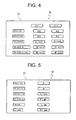
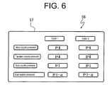
- the display 56 has a screen 57 (see Figs. 4 to 6 ) where data and information of various items are indicated. Data for respective items may be newly input and rewritten directly on the screen 57.
- the initial pressure gauge 21 measures the initial pressure of compressed air supplied from the air compressor and transmits its data to the controller 43.
- the main pressure gauge 19 measures the pressure of compressed air regulated by the main regulator 20
- the sub-pressure gauge 32 measures the pressure of compressed air regulated by the sub-regulator 33
- the sub-pressure gauge 40 measures the pressure of compressed air regulated by the sub-regulator 41. Such pressure data is respectively transmitted to the controller 43.
- the controller 43 previously stores data regarding the time when the pin 8 of the weft measuring and storing device 9, the main valve 12, the tandem valve 14 and the sub-valves 27, 36 should start to operate and also data of the duration of such operation.
- the controller 43 transmits signals to the pin 8, the main valve 12 and the tandem valve 14 to start insertion of weft yarn Y, and subsequently transmits signals to the sub-valves 27, 36 during the insertion of weft yarn Y, so that insertion of weft yarn Y is completed.
- the controller 43 counts the number of detection signals transmitted from the detector 10 each indicative of a balloon formed by the weft yarn Y, and transmits a signal to the pin 8 to engage with the weft yarn Y when the counted number of balloons reaches a predetermined value.
- the time when the number of balloons reaches the predetermined value is detected by an encoder (not shown) in terms of the angular position of the air jet loom 1, and the angular position then detected is stored in the controller 43 as the time of weft release completion.
- the controller 43 determines whether or not any failure of weft insertion has occurred and stores the angular position of the air jet loom 1 then detected by the encoder as the time of weft insertion completion.
- the controller 43 registers and stores therein plural databases 65, 66, 67 as shown in Fig. 2 , in which data of optimum sub-nozzle pressure is linked to data of loom speed for different types of reed dent.
- the databases 65, 66, 67 are made for three different sets of fabric and weaving conditions.
- the database 65 is shown in the form of a diagram
- the horizontal axis represents the loom speed
- the vertical axis represents the optimum sub-nozzle pressure.
- lines 60, 61, 62 show the relation between the optimum sub-nozzle pressure and the loom speed for three different types T1, T2, T3 of the reed dent 58.
- the diagram of Fig. 2 shows only three different types of the reed dent 58 for simplicity, there may be four or more types of the reed dent 58 in an actual diagram. The following will describe how to prepare the databases shown in Fig. 2 .
- weaving operation is performed previously under specific fabric and weaving conditions, and a diagram of the relation of the time of weft insertion completion, angular difference and sub-nozzle pressure as shown in Fig. 3 is prepared based on the data obtained from the detectors 10, 11, the main pressure gauge 19 and the sub-pressure gauge 32 during the above weaving operation.
- the horizontal axis represents the sub-nozzle pressure or the air injection pressure of the sub-nozzles 3
- the left-hand side vertical axis represents the time of weft insertion completion
- the right-hand side vertical axis represents the angular difference that is indicative of the difference between the time of weft insertion completion and the time of weft release completion.
- line 63 that is indicative of the variation of the time of weft insertion completion with a change of the sub-nozzle pressure and line 64 that is indicative of the variation of the angular difference with a change of the sub-nozzle pressure are drawn based on the data that is obtained during the weaving operation in which the sub-nozzle pressure is varied so that the time of weft insertion completion is stabilized.
- the time of weft insertion completion is constant regardless of the sub-nozzle pressure. This is because the time of weft insertion completion needs to be maintained within a given range for stable weft insertion.
- the angular difference is approximately constant when the sub-nozzle pressure is higher than the pressure P at the point X, but gradually increased as the sub-nozzle pressure is decreased from the pressure P at the point X.
- a factor of such an increase of the angular difference is as follows.
- the pressure of air injected from the main nozzle 5 or the tandem nozzle 6 is increased so as to increase weft insertion speed and hence to keep the time of weft insertion completion constant.
- Increasing the air injection pressure of the main nozzle 5 or the tandem nozzle 6 accelerates the time of weft release completion, thereby increasing the angular difference, that is the difference between the constant time of weft insertion completion and the time of weft release completion. Excessive increase of the speed of weft insertion by the main nozzle 5 or the tandem nozzle 6 may result in unstable flight of the weft yarn Y.
- the pressure P at the point X or higher should preferably be selected based on the line 64 of Fig. 3 that is indicative of the change of angular difference.
- the line 64 indicative of the change of angular difference is approximately constant when the sub-nozzle pressure is higher than the pressure P at the point X.
- the pressure P at the point X is selected as the optimum sub-nozzle pressure that results in constant time of weft insertion completion and stable flight of the weft yarn Y and also allows less consumption of air by the sub-nozzles which contributes to an energy saving.
- the line 64 indicative of the change of angular difference is obtained through the weaving operation under given fabric conditions and weaving conditions.
- the inventors of the present invention have found through various experiments that the optimum sub-nozzle pressure P significantly changes depending on the loom speed of the air jet loom 1 and the type of the reed dent 58 which are part of the weaving conditions.
- the type of the reed dent 58 can be specified by the dent thickness, the dent count, the space ratio.
- the dent thickness is used to specify the type of the reed dent 58, and indicated as an item of the weaving condition on the screen 57 of the display 56 (see Fig. 5 ).
- the databases 65, 66, 67 are registered and stored in the controller 43.
- the databases 65, 66, 67 may be stored not only in the form of a diagram, but also in the form of a mathematical formula made based on such diagram.
- the controller 43 stores therein a program that allows optimum sub-nozzle pressure to be selected from the database 65, 66 or 67 based on the fabric conditions and the weaving conditions including the type of reed dent and the loom speed, and also allows the selected optimum sub-nozzle pressure to be indicated on the display 56.
- the following will describe an example of setting condition for weft insertion by the program stored in the controller 43 with reference to Figs. 4 to 6 .
- part of the fabric conditions and weaving conditions for weft yarn Y is indicated on the screen 57 of the display 56.
- weft yarn type, weft yarn count, weft yarn density are indicated as the items of the fabric condition
- the time of weft insertion start and the time of weft insertion completion are indicated as the items of the weaving condition, for each of the colors 1, 2 that corresponds to the two sets of weft insertion devices 2 for multicolor weft insertion.
- Data for the respective items that is previously stored in the controller 43 or input on the screen 57 is also indicated.
- part of the fabric conditions and weaving conditions for warp yarns and other condition is also indicated on the same screen 57 of the display 56.
- warp yarn type, warp yarn count, warp yarn density are indicated as the items of the fabric condition
- reed dent thickness indicative of the type of the reed dent 58, reed width, loom speed are indicated as the items of the weaving condition.
- Data for the respective items that is previously stored in the controller 43 or input on the screen 57 is also indicated.
- the controller 43 reads out the database 65 of Fig. 2 whose fabric and weaving conditions correspond to the conditions shown in Figs. 4, 5 . Then, based on the reed dent thickness T1 and the loom speed R1 indicated on the screen 57 (see Fig. 5 ), the sub-nozzle pressure linked to such T1, R1 is searched in the database 65.
- the pressure P1 linked to the loom speed R1 on the line 60 indicative of optimum sub-nozzle pressure for the type of reed dent or reed dent thickness T1 is selected from the database 65 by the controller 43 as the optimum sub-nozzle pressure, and the selected sub-nozzle pressure is indicated on the screen 57 (see Fig. 6 ).
- the main nozzle pressure, the tandem nozzle pressure, the sub-nozzle pressure and the end nozzle pressure as the items of weaving conditions are indicated for each of the respective colors 1, 2 on the screen 57.
- the optimum sub-nozzle pressure of P1 selected from the database 65 of Fig. 2 by the controller 43 is indicated in the field of the sub-nozzle pressure.
- the end nozzle pressure of P1- ⁇ , or the pressure that is lower than the optimum sub-nozzle pressure P1 by ⁇ , is indicated in the field of the end nozzle pressure.
- the indication of such pressures on the screen 57 as shown in Fig. 6 may be used as reference by an operator of the loom in adjusting the corresponding conditions. It may be so arranged that such adjustment is done automatically. In this case, indication of the pressure as in Fig. 6 may be dispensed with.
- the controller 43, the plural databases 65, 66, 67 and the program for selecting optimum sub-nozzle pressure cooperate to constitute the apparatus for setting the weft insertion condition.
- the use of the database 65, 66, 67 shown in Fig. 2 results in constant time of weft insertion completion and stable flight of weft yarn Y during the weft insertion, and also allows possible reduction of the pressure of compressed air for injection from the sub-nozzles 3 and the end nozzles 4, which leads to a significant energy saving in the air jet loom 1.
- Preparing plural databases such as 65, 66, 67 allows easy selection of optimum sub-nozzle pressure for any kind of fabric.
- An apparatus for setting weft insertion condition in an air jet loom includes a weft insertion device causing a weft yarn to move by compressed air injected from a main nozzle and plural sub-nozzles arranged in the direction of weft insertion, and a controller storing fabric conditions and weaving conditions.
- the controller stores a database in which data of optimum sub-nozzle pressure is linked to data of loom speed for different types of reed dent.
- the data of optimum sub-nozzle pressure is obtained based on the variation of angular difference between the time of weft insertion completion and the time of weft release completion in the fabric conditions and the weaving conditions.
- the controller selects the optimum sub-nozzle pressure from the database based on the fabric conditions, the type of reed dent and the loom speed.
Landscapes
- Engineering & Computer Science (AREA)
- Textile Engineering (AREA)
- Looms (AREA)
Applications Claiming Priority (1)
| Application Number | Priority Date | Filing Date | Title |
|---|---|---|---|
| JP2012252918A JP2014101594A (ja) | 2012-11-19 | 2012-11-19 | エアジェット織機における緯入れ条件設定装置 |
Publications (1)
| Publication Number | Publication Date |
|---|---|
| EP2733242A2 true EP2733242A2 (de) | 2014-05-21 |
Family
ID=49485550
Family Applications (1)
| Application Number | Title | Priority Date | Filing Date |
|---|---|---|---|
| EP20130190008 Withdrawn EP2733242A2 (de) | 2012-11-19 | 2013-10-24 | Vorrichtung zur Schussfadeneintragungsbedingung in einer Luftdüsenwebmaschine |
Country Status (3)
| Country | Link |
|---|---|
| EP (1) | EP2733242A2 (de) |
| JP (1) | JP2014101594A (de) |
| CN (1) | CN103820923B (de) |
Cited By (1)
| Publication number | Priority date | Publication date | Assignee | Title |
|---|---|---|---|---|
| CN105133151A (zh) * | 2015-08-05 | 2015-12-09 | 淄博银仕来纺织有限公司 | 一种喷气织机的引纬装置及其引纬工艺 |
Families Citing this family (4)
| Publication number | Priority date | Publication date | Assignee | Title |
|---|---|---|---|---|
| JP6172186B2 (ja) * | 2015-03-17 | 2017-08-02 | 株式会社豊田自動織機 | エアジェット織機における緯入れ制御方法及びエアジェット織機における緯入れ装置 |
| CN104790099B (zh) * | 2015-04-28 | 2016-05-11 | 宁波市东盛纺织有限公司 | 一种具有导气杆的喷气织机 |
| CN104790100B (zh) * | 2015-04-28 | 2016-05-11 | 宁波市东盛纺织有限公司 | 一种喷气织机 |
| CN104790101B (zh) * | 2015-04-28 | 2016-08-24 | 宁波市东盛纺织有限公司 | 一种宽幅喷气织机 |
Citations (1)
| Publication number | Priority date | Publication date | Assignee | Title |
|---|---|---|---|---|
| JPH04241135A (ja) | 1990-12-29 | 1992-08-28 | Toyota Autom Loom Works Ltd | ジェットルームにおける緯入れ用圧力制御装置 |
Family Cites Families (8)
| Publication number | Priority date | Publication date | Assignee | Title |
|---|---|---|---|---|
| JP2671514B2 (ja) * | 1989-07-26 | 1997-10-29 | 株式会社豊田自動織機製作所 | 多色ジェットルームにおける緯入れ制御装置 |
| JPH04240249A (ja) * | 1991-01-22 | 1992-08-27 | Nissan Motor Co Ltd | 空気噴射式織機の緯入れ制御装置 |
| JP2611702B2 (ja) * | 1991-03-06 | 1997-05-21 | 株式会社豊田自動織機製作所 | ジェットルームにおける起動方法 |
| JP2898773B2 (ja) * | 1991-03-08 | 1999-06-02 | 津田駒工業株式会社 | ジェットルームの緯入れ制御装置 |
| CN1069302A (zh) * | 1991-08-12 | 1993-02-24 | 日产自动车株式会社 | 流体喷射织机及其操作方法 |
| JPH0586543A (ja) * | 1991-09-20 | 1993-04-06 | Nissan Motor Co Ltd | 流体噴射式織機 |
| JP4111864B2 (ja) * | 2003-05-08 | 2008-07-02 | 津田駒工業株式会社 | 流体噴射式織機の噴射圧力設定方法、噴射圧力設定装置および緯入れ装置 |
| JP2012224959A (ja) * | 2011-04-20 | 2012-11-15 | Tsudakoma Corp | 空気噴射式織機におけるサブノズルの噴射角度位置の調整方法及び装置 |
-
2012
- 2012-11-19 JP JP2012252918A patent/JP2014101594A/ja active Pending
-
2013
- 2013-10-24 EP EP20130190008 patent/EP2733242A2/de not_active Withdrawn
- 2013-11-18 CN CN201310574387.7A patent/CN103820923B/zh not_active Expired - Fee Related
Patent Citations (1)
| Publication number | Priority date | Publication date | Assignee | Title |
|---|---|---|---|---|
| JPH04241135A (ja) | 1990-12-29 | 1992-08-28 | Toyota Autom Loom Works Ltd | ジェットルームにおける緯入れ用圧力制御装置 |
Cited By (2)
| Publication number | Priority date | Publication date | Assignee | Title |
|---|---|---|---|---|
| CN105133151A (zh) * | 2015-08-05 | 2015-12-09 | 淄博银仕来纺织有限公司 | 一种喷气织机的引纬装置及其引纬工艺 |
| CN105133151B (zh) * | 2015-08-05 | 2017-07-14 | 淄博银仕来纺织有限公司 | 一种喷气织机的引纬装置及其引纬工艺 |
Also Published As
| Publication number | Publication date |
|---|---|
| CN103820923A (zh) | 2014-05-28 |
| CN103820923B (zh) | 2015-09-02 |
| JP2014101594A (ja) | 2014-06-05 |
Similar Documents
| Publication | Publication Date | Title |
|---|---|---|
| EP2733243B1 (de) | Eine Luftdüsenwebmaschine mit einer Vorrichtung zur Anzeige der Druckluftdurchflussmenge | |
| CN107034575B (zh) | 喷气织机中的纬纱行进状态监视方法 | |
| JP2021147715A (ja) | エアジェット織機の緯糸ブレーキ制御装置 | |
| JP6319262B2 (ja) | エアジェット織機における緯入れ制御装置 | |
| JP2015094059A (ja) | エアジェット織機の緯糸検知装置 | |
| US7819142B2 (en) | Method for introducing a weft thread in an air weaving machine and air weaving machine | |
| CN103820923B (zh) | 用于设定空气喷射织机中的纬纱插入条件的设备 | |
| EP4019678B1 (de) | Luftdüsenwebmaschine mit schusseintragssteuergerät | |
| JP4111864B2 (ja) | 流体噴射式織機の噴射圧力設定方法、噴射圧力設定装置および緯入れ装置 | |
| EP3323920B1 (de) | Schussfadenlaufzustandserkennungsvorrichtung in einer luftdüsenwebmaschine | |
| EP2765229B1 (de) | Luftdüsenwebmaschine mit einer Anzeigevorrichtung | |
| JP6447533B2 (ja) | エアジェット織機における緯入れ制御方法及び緯入れ制御装置 | |
| CN100371512C (zh) | 打纬时间计算方法及投纬条件设定方法 | |
| JP2004339674A (ja) | 横糸を挿入するための方法および装置 | |
| JP2020105652A (ja) | エアジェット織機のフィルタ目詰まり検出装置 | |
| EP3498902B1 (de) | Verfahren zur diagnose der schussfadeneinführung in einer luftdüsenwebmaschine | |
| JP2021179033A (ja) | エアジェット織機のサブノズル噴射方向調整装置 | |
| EP4474546A1 (de) | Informationsanzeigevorrichtung für luftdüsenwebmaschine | |
| JP6787141B2 (ja) | エアジェット織機における緯入れ診断方法、及びエアジェット織機における緯入れ診断装置 | |
| JP6380434B2 (ja) | ジェットルームにおける緯糸検知方法及び緯糸検知装置 |
Legal Events
| Date | Code | Title | Description |
|---|---|---|---|
| PUAI | Public reference made under article 153(3) epc to a published international application that has entered the european phase |
Free format text: ORIGINAL CODE: 0009012 |
|
| 17P | Request for examination filed |
Effective date: 20131024 |
|
| AK | Designated contracting states |
Kind code of ref document: A2 Designated state(s): AL AT BE BG CH CY CZ DE DK EE ES FI FR GB GR HR HU IE IS IT LI LT LU LV MC MK MT NL NO PL PT RO RS SE SI SK SM TR |
|
| AX | Request for extension of the european patent |
Extension state: BA ME |
|
| STAA | Information on the status of an ep patent application or granted ep patent |
Free format text: STATUS: THE APPLICATION HAS BEEN WITHDRAWN |
|
| 18W | Application withdrawn |
Effective date: 20160502 |