EP2733472B1 - Appareil de mesure de débit à noyau magnétique et procédé de fonctionnement d'appareils de mesure de débit à noyau magnétique - Google Patents
Appareil de mesure de débit à noyau magnétique et procédé de fonctionnement d'appareils de mesure de débit à noyau magnétique Download PDFInfo
- Publication number
- EP2733472B1 EP2733472B1 EP13005293.9A EP13005293A EP2733472B1 EP 2733472 B1 EP2733472 B1 EP 2733472B1 EP 13005293 A EP13005293 A EP 13005293A EP 2733472 B1 EP2733472 B1 EP 2733472B1
- Authority
- EP
- European Patent Office
- Prior art keywords
- measuring tube
- nuclear magnetic
- measuring
- segment
- measuring device
- Prior art date
- Legal status (The legal status is an assumption and is not a legal conclusion. Google has not performed a legal analysis and makes no representation as to the accuracy of the status listed.)
- Active
Links
Images
Classifications
-
- G—PHYSICS
- G01—MEASURING; TESTING
- G01F—MEASURING VOLUME, VOLUME FLOW, MASS FLOW OR LIQUID LEVEL; METERING BY VOLUME
- G01F1/00—Measuring the volume flow or mass flow of fluid or fluent solid material wherein the fluid passes through a meter in a continuous flow
- G01F1/05—Measuring the volume flow or mass flow of fluid or fluent solid material wherein the fluid passes through a meter in a continuous flow by using mechanical effects
- G01F1/34—Measuring the volume flow or mass flow of fluid or fluent solid material wherein the fluid passes through a meter in a continuous flow by using mechanical effects by measuring pressure or differential pressure
- G01F1/36—Measuring the volume flow or mass flow of fluid or fluent solid material wherein the fluid passes through a meter in a continuous flow by using mechanical effects by measuring pressure or differential pressure the pressure or differential pressure being created by the use of flow constriction
- G01F1/40—Details of construction of the flow constriction devices
- G01F1/44—Venturi tubes
-
- G—PHYSICS
- G01—MEASURING; TESTING
- G01F—MEASURING VOLUME, VOLUME FLOW, MASS FLOW OR LIQUID LEVEL; METERING BY VOLUME
- G01F1/00—Measuring the volume flow or mass flow of fluid or fluent solid material wherein the fluid passes through a meter in a continuous flow
- G01F1/74—Devices for measuring flow of a fluid or flow of a fluent solid material in suspension in another fluid
-
- G—PHYSICS
- G01—MEASURING; TESTING
- G01F—MEASURING VOLUME, VOLUME FLOW, MASS FLOW OR LIQUID LEVEL; METERING BY VOLUME
- G01F1/00—Measuring the volume flow or mass flow of fluid or fluent solid material wherein the fluid passes through a meter in a continuous flow
- G01F1/56—Measuring the volume flow or mass flow of fluid or fluent solid material wherein the fluid passes through a meter in a continuous flow by using electric or magnetic effects
- G01F1/58—Measuring the volume flow or mass flow of fluid or fluent solid material wherein the fluid passes through a meter in a continuous flow by using electric or magnetic effects by electromagnetic flowmeters
-
- G—PHYSICS
- G01—MEASURING; TESTING
- G01F—MEASURING VOLUME, VOLUME FLOW, MASS FLOW OR LIQUID LEVEL; METERING BY VOLUME
- G01F1/00—Measuring the volume flow or mass flow of fluid or fluent solid material wherein the fluid passes through a meter in a continuous flow
- G01F1/66—Measuring the volume flow or mass flow of fluid or fluent solid material wherein the fluid passes through a meter in a continuous flow by measuring frequency, phase shift or propagation time of electromagnetic or other waves, e.g. using ultrasonic flowmeters
-
- G—PHYSICS
- G01—MEASURING; TESTING
- G01F—MEASURING VOLUME, VOLUME FLOW, MASS FLOW OR LIQUID LEVEL; METERING BY VOLUME
- G01F1/00—Measuring the volume flow or mass flow of fluid or fluent solid material wherein the fluid passes through a meter in a continuous flow
- G01F1/76—Devices for measuring mass flow of a fluid or a fluent solid material
- G01F1/78—Direct mass flowmeters
- G01F1/80—Direct mass flowmeters operating by measuring pressure, force, momentum, or frequency of a fluid flow to which a rotational movement has been imparted
- G01F1/84—Coriolis or gyroscopic mass flowmeters
Definitions
- the invention relates to a nuclear magnetic flow measuring device for measuring the flow of a multiphase medium flowing through a measuring tube, with a nuclear magnetic measuring device, the nuclear magnetic measuring device being arranged around the measuring tube.
- the invention also relates to methods for operating nuclear magnetic flowmeters.
- the atomic nuclei of the elements that have a nuclear spin also have a magnetic moment caused by the nuclear spin.
- the nuclear spin can be understood as an angular momentum that can be described by a vector, and accordingly the magnetic moment can also be described by a vector that is aligned parallel to the vector of the angular momentum.
- the vector of the magnetic moment of an atomic nucleus is aligned parallel to the vector of the macroscopic magnetic field at the location of the atomic nucleus.
- the vector of the magnetic moment of the atomic nucleus precesses around the vector of the macroscopic magnetic field at the location of the atomic nucleus.
- the frequency of the precession is called the Larmor frequency ⁇ L and is proportional to the magnitude of the magnetic field strength B.
- y is the gyromagnetic ratio, which is the maximum for hydrogen nuclei.
- Measurement methods that influence the precession of atomic nuclei of a medium in the presence of a macroscopic magnetic field through excitation by means of a controlled magnetic field and evaluate the effect of the influence are called nuclear magnetic resonance measurement methods.
- the electrical signals induced by the precessing atomic nuclei after excitations in a sensor coil are usually used as the output variable for the evaluation.
- the prerequisite for the measurement of a multi-phase medium is that the individual phases of the medium can be excited to distinguishable nuclear magnetic resonances.
- the size of the electrical signals induced by the precessing atomic nuclei of a phase of the medium in the sensor coil depends on the number of precessing atomic nuclei per volume element in this phase, therefore depending on the density of the phase, but also depending on the duration of the precessing atomic nuclei in the influencing controlled magnetic field. Consequently, the size of the electrical signals in the liquid phases of the medium is larger than in the gaseous phases.
- the measuring accuracy for the measurement of the liquid phases of the medium can be sufficiently precise, while the smaller size of the electrical signals in the gaseous phases affects the measuring accuracy of the nuclear magnetic flowmeters for the measurement of the gaseous phase, especially if the gaseous phase has a relatively low density and / or if the gaseous phase flows through the measuring tube at a relatively high speed.
- Nuclear magnetic flow measuring devices can e.g. B. can be used for flow measurement of the multi-phase medium produced from oil wells.
- This medium essentially consists of the liquid phases of crude oil and salt water and the gaseous phase of natural gas, whereby all phases contain the hydrogen nuclei necessary for nuclear magnetic resonances and can be excited to different nuclear magnetic resonances.
- Test separators can also be used to measure the medium extracted from oil sources.
- the conveyed medium is introduced into test separators over a period of time, and the test separators separate the individual phases of the medium from one another and determine the proportions of the individual phases in the medium.
- test separators are unable to reliably separate crude oil fractions below 5%. Since the crude oil share of all sources is steadily decreasing and the crude oil share of a large number of sources is already less than 5%, it is currently not possible to exploit these sources economically using test separators. To even sources with a very low In order to continue to be able to exploit the crude oil content, correspondingly accurate flowmeters are required for the crude oil medium, which consists of several phases. Nuclear magnetic flowmeters are particularly suitable for this.
- the nuclear magnetic flow meter additionally has a further measuring device which implements a different measuring principle.
- Different measuring principles for flow measurement have different advantages and disadvantages.
- the disadvantages of one measuring principle can be at least partially compensated for by the advantages of the other measuring principle.
- the nuclear magnetic measuring device can in particular be combined with a differential pressure flow measuring device, an ultrasonic flow measuring device, a Coriolis flow measuring device and, if appropriate, also with a magnetic-inductive flow measuring device.
- the further measuring device is a differential pressure flow measuring device, which is designed to measure the differential pressure of the medium in the measuring tube.
- a nuclear magnetic flow meter is from the WO 98/59220 known.
- the object of the present invention is therefore to provide a nuclear magnetic flow measuring device with an improved measuring accuracy of Flow measurement for the gaseous phase and the specification of methods for operating nuclear magnetic flowmeters.
- the nuclear magnetic flow measuring device consists of a nuclear magnetic measuring device and a differential pressure flow measuring device which implements a measuring principle other than the nuclear magnetic measuring principle.
- This measuring device is one with which the multiphase medium flowing through the measuring tube as a whole can be measured with sufficient accuracy.
- one obtains two sufficiently precise measured values with the nuclear magnetic flow measuring device namely with the additionally provided measuring device a sufficiently precise measured value for the multiphase medium flowing through the measuring tube overall and with the nuclear magnetic measuring device a sufficiently accurate measured value for the liquid phase or the liquid phases of the multiphase medium flowing through the measuring tube.
- a differential pressure flow measuring device having a Venturi tube can be used to determine the gaseous phase of a multiphase medium flowing through a measuring tube.
- the proportion of the liquid phase or the liquid phases must be taken into account, the density of the multiphase medium flowing through the measuring tube must also be taken into account. If a measured value has been determined with a differential pressure flow measuring device having a Venturi tube, then the gaseous phase can be estimated with a certain accuracy.
- the differential pressure flow measuring device which is designed for measuring the differential pressure of the medium in the measuring tube, preferably has at least one pressure meter at at least two measuring points different in the longitudinal direction of the measuring tube.
- the measuring points each having at least one pressure meter are provided at the points on the measuring tube at which the pressure of the flowing medium in the measuring tube differs from one another due to the cross-sectional profile.
- the further measuring device is designed as a differential pressure flow measuring device.
- a first preferred embodiment of the nuclear magnetic flow measuring device according to the invention with a differential pressure flow measuring device as a further measuring device is characterized in that the measuring tube consists of a first partial measuring tube and a second partial measuring tube and that the nuclear magnetic measuring device is arranged around the first partial measuring tube and the further measuring device in connection with the second Partial measuring tube is realized.
- the measuring tube can have at least one first segment, a second segment following the first segment and a third segment following the second segment in the longitudinal direction of the measuring tube, the Cross-sectional area in the first segment and in the third segment is constant and the cross-sectional area in the second segment can have a course which deviates from the cross-sectional areas in the first segment and in the third segment.
- This embodiment of a nuclear magnetic flowmeter in which the measuring tube in the longitudinal direction of the measuring tube has at least a first segment, a second segment following the first segment and a third segment following the second segment, is particularly useful if the measuring tube consists of a first There is a partial measuring tube and a second partial measuring tube and the segments of the measuring tube are provided in the second partial measuring tube.
- the cross-sectional areas in the second segment are preferably smaller than the cross-sectional areas in the first segment and in the third segment.
- the measuring tube in the second segment if the measuring tube consists of a first partial measuring tube and a second partial measuring tube, preferably in the second partial measuring tube, can have an insert which can be fastened in the second segment.
- This insert can preferably have a conical cross-sectional shape in the longitudinal direction of the measuring tube.
- the first segment, the second segment and the third segment can together form a Venturi tube.
- the measuring tube consists of a first partial measuring tube and a second partial measuring tube and if the first segment, the second segment and the third segment of the measuring tube are provided in the second partial measuring tube, then the second partial measuring tube is designed as a Venturi tube as a whole.
- a completely different embodiment of a nuclear magnetic flow meter according to the invention is also conceivable, namely one in which the cross-sectional area in the second segment of the measuring tube is larger than the cross-sectional areas in the first segment of the measuring tube and in the third segment of the measuring tube.
- the further measuring device can also be an ultrasonic flow measuring device.
- a nuclear magnetic flowmeter can be used particularly well if the multiphase medium flowing through the measuring tube - and thus also its gaseous phase - flows through the measuring tube at a relatively high speed, in particular also when the multiphase medium passes through the measuring tube flows to "moist gas" in which the liquid phase is in the form of drops in the gaseous phase, or when the inside of the measuring tube is wetted by the liquid phase or the liquid phases.
- Fig. 1 is a first embodiment and in the Fig. 2 a second embodiment of the nuclear magnetic flow meter 1 according to the invention is shown schematically.
- Each of the nuclear magnetic flow measuring devices 1 comprises a nuclear magnetic measuring device 2 for measuring the flow of a multiphase medium 4 flowing through a measuring tube 3.
- the nuclear magnetic measuring device 2 is arranged around the measuring tube 3.
- a further measuring device is provided which works according to a different measuring principle than the nuclear magnetic measuring principle, namely the further measuring device is a differential pressure flow measuring device 5.
- the differential pressure flow measuring device 5 has a pressure meter 8a at two measuring points 6a, 6b different in the longitudinal direction 7 of the measuring tube 3 , 8b.
- the pressure measurement of the medium 4 in the measuring tube 3 takes place through openings in the wall of the measuring tube 3.
- There are two measuring points 6a, 6b which are offset in the longitudinal direction 7 of the measuring tube 3 each provided a pressure gauge 8a, 8b.
- other pressure gauges can also be provided.
- the resulting redundancy increases the accuracy of the pressure measurements.
- Commercially available pressure sensors are used as pressure sensors in the pressure gauges 8a, 8b.
- the measuring tube 3 has a constant inner cross-sectional area in the longitudinal direction 7 of the measuring tube 3. Because of the flow of the medium 4 in the measuring tube 3 Friction between the medium 4 and the measuring tube 3, the pressure of the medium 4 in the measuring tube 3 drops in the flow direction of the medium 4 in the longitudinal direction 7 of the measuring tube.
- the pressure gauges 8a, 8b accordingly measure pressures of different sizes; the pressure at the measuring point 6a is higher than the pressure at the measuring point 6b.
- the measuring tube 3 consists of a first partial measuring tube 9a and a second partial measuring tube 9b.
- the nuclear magnetic measuring device 2 is arranged around the first partial measuring tube 9a.
- the further measuring device that is to say the differential pressure flow measuring device 5, is implemented in connection with the second partial measuring tube 9b.
- the first partial measuring tube 9a is therefore part of the partially magnetic measuring device 2, while the second partial measuring tube 9b is part of the differential pressure flow measuring device 5.
- the nuclear magnetic measuring device 2 with the first partial measuring tube 9a and the differential pressure flow measuring device 5 with the second partial measuring tube 9b form the nuclear magnetic flowmeter 1 according to the invention, which is of modular construction.
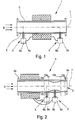
- the second partial measuring tube 9b of the measuring tube 3 has a first segment 10a, a second segment 10b following the first segment 10a and a third segment 10c following the second segment 10b.
- the cross-sectional areas in the first segment 10a and in the third segment 10c are constant, while the cross-sectional area in the second segment 10b has a profile which deviates from the cross-sectional areas in the first segment 10a and in the third segment 10c.
- the cross-sectional areas in the second segment 10b are smaller than the cross-sectional areas in the first segment 10a and in the third segment 10c.
- the segments 10a, 10b and 10c of the second partial measuring tube 9b form a Venturi tube.
- the pressure difference between the pressure gauges 8a and 8b is greater than the pressure difference between the pressure gauges 8a and 8b in the first exemplary embodiment. This higher pressure difference can lead to better measurement accuracy.
- the first partial measuring tube 9a of the measuring tube 3 is arranged in the longitudinal direction 7 of the measuring tube 3, that is to say in the flow direction of the medium 4, in front of the second partial measuring tube 9b.
- the first partial measuring tube 9a can either represent the inlet area of the nuclear magnetic flowmeter 1 according to the invention or its outlet area.
- the nuclear magnetic measuring device 2 and the first partial measuring tube 9a together form the nuclear magnetic flow meter described at the beginning.
- the second partial measuring tube 9b and the differential pressure flow measuring device 5 expand the nuclear magnetic flow meter modularly to the nuclear magnetic flow meter 1 according to the invention.
- the inner cross-sectional area of the second measuring tube 9b of the measuring tube 3 is divided into three segments along the longitudinal axis 7, namely into a first segment 10a, a second segment 10b following the first segment 10a in the direction of flow of the medium 4 and a further segment onto the second segment 10b following third segment 10c in the flow direction.
- the cross-sectional areas along the longitudinal axis 7 in both the first segment 10a and in the third segment 10c are constant, while the cross-sectional area course along the longitudinal axis 7 in the second segment 10b has a cross-sectional area that differs from the cross-sectional areas in the first segment 10a and in the second segment 10b.
- the cross-sectional area of the segments 10a, 10b and 10c together forms a Venturi tube.
- the longitudinal points 6a, 6b, at which the two pressure gauges 8a, 8b are arranged, are provided at points on the longitudinal axis 7 at which the pressures of the flowing medium 4 in the measuring tube 9b differ from one another due to the cross-sectional profile; the pressure of the medium 4 measured by the pressure meter 8a is higher than the pressure measured by the pressure meter 8b.
- the pressure difference between the pressure gauges 8a, 8b is greater than the pressure difference between the pressure gauges 8a, 8b in the first exemplary embodiment.
- the higher pressure difference is also accompanied by a higher flow resistance of the medium 4 in the measuring tube 3.
- a higher pressure difference results in better measuring precision.
- the first partial measuring tube 9a When viewed in the flow direction of the medium 4, the first partial measuring tube 9a is arranged in front of the second partial measuring tube 9b. However, it is also possible to arrange the first partial measuring tube 9a behind the second partial measuring tube 9b. Both an inlet area before and an outlet area after the second partial measuring tube 9b are required for precise pressure measurement. Depending on the arrangement of the first partial measuring tube 9a in relation to the second partial measuring tube 9b, the first partial measuring tube 9a can represent either the inlet area or the outlet area.
- the determination of the measured value for the multi-phase flowing through the measuring tube 3 is preferred Medium 4 is repeated, preferably repeated several times, and an average value is formed from the measurement values obtained and is used to determine the measurement value for the gaseous phase of the multiphase medium 4 flowing through the measuring tube 3 from the measurement value formed, the measurement value for the liquid phase or the liquid phase Subtracted phases of the multiphase medium flowing through the measuring tube 3.
- the previously mentioned method for operating a nuclear magnetic flow measuring device 1 is based on a “black-and-white observation”, which does not take into account the fact that the obtaining of a sufficiently precise first measured value for the multiphase medium flowing through the measuring tube 3 as a whole in any case if a differential pressure flow measuring device 5 is used as a further measuring device, is dependent on the density of the medium 4 flowing through the measuring tube 3 and that the density of the medium 4 flowing through the measuring tube 3 is in turn dependent on the composition of the medium through the measuring tube 3 flowing multi-phase medium 4, namely the proportions of the liquid phase or the liquid phases and the gaseous phase in the multi-phase medium 4 flowing overall through the measuring tube 3.
- netic flow measuring device 1 for flow measurement of a multiphase medium 4 flowing through a measuring tube 3, the nuclear magnetic flow measuring device 1 having a nuclear magnetic measuring device 2 and additionally a further measuring device implementing another measuring principle, namely a differential pressure flow measuring device 5, which is characterized in that with the further Measuring device is determined several times, namely successively a measured value for the multiphase medium 4 flowing through the measuring tube 3 and that the (n + 1) th determination takes into account the measured value obtained in the n th determination.
- the (n + 1) -th determination of the measured value for the multiphase medium 4 flowing through the measuring tube 3 as a whole takes into account the measured value obtained in the n-th determination, so the dependence of the density of the medium flowing through the measuring tube 3 is taken into account 4 of the composition of the multiphase medium 4 flowing through the measuring tube 3 is taken into account.
- the multiple determination of the multiphase medium 3 flowing through the measuring tube 3 with the aid of the further measuring device is preferably carried out until the difference between the measurement value obtained in the (n + 1) determination and the measurement value obtained in the nth determination is smaller than a predetermined deviation which is considered to be permissible, for example a deviation of 3% or less, possibly also of 1%.
- an algorithm or algorithms are used in the second determination, in the third determination, up to the (n + 1) determination, determine the density of the multiphase medium 4 flowing through the measuring tube 3 on the basis of the composition of the multiphase medium 4 flowing through the measuring tube 3 overall, that is to say the proportion of the liquid phase or the liquid phases on the one hand and the gaseous phase on the other hand.
Landscapes
- Physics & Mathematics (AREA)
- Fluid Mechanics (AREA)
- General Physics & Mathematics (AREA)
- Measuring Volume Flow (AREA)
Claims (13)
- Débitmètre magnétique nucléaire pour la mesure du débit d'un fluide multiphasique (4) circulant dans un tube de mesure (3) et muni d'un dispositif de mesure magnétique nucléaire (2),
dans lequel le dispositif de mesure magnétique nucléaire (2) est disposé autour du tube de mesure (3),
dans lequel, un autre dispositif de mesure mettant en œuvre un principe de mesure différent est en outre prévu pour la mesure du débit de la totalité du fluide multiphasique (4) circulant dans le tube de mesure,
dans lequel l'autre dispositif de mesure est un dispositif de mesure de débit à pression différentielle (5), et
dans lequel le dispositif de mesure de débit à pression différentielle (5) est conçu pour mesurer la pression différentielle du fluide multiphasique (4) dans le tube de mesure (3),
caractérisé en ce que le dispositif de mesure magnétique nucléaire est conçu pour mesurer le débit de la phase ou des phases liquide(s),
en ce qu'il est prévu respectivement au moins un manomètre (8a, 8b) en au moins deux points de mesure (6a, 6b) différents dans la direction longitudinale (7) du tube de mesure (3), et
en ce que le débitmètre magnétique nucléaire est conçu, afin de déterminer une valeur de mesure pour la phase gazeuse du fluide multiphasique circulant dans le tube de mesure, pour soustraire à la valeur de mesure obtenue au moyen du dispositif de mesure supplémentaire pour la totalité du fluide multiphasique circulant dans le tube de mesure, la valeur de mesure obtenue au moyen du dispositif de mesure magnétique nucléaire pour la phase liquide ou les phases liquides du fluide multiphasique circulant dans le tube de mesure. - Débitmètre magnétique nucléaire selon la revendication 1, caractérisé en ce que les points de mesure (6a, 6b) présentant chacun au moins un manomètre (8a, 8b) sont prévus aux emplacements du tube de mesure (3) auxquels la pression du fluide en écoulement (4) dans le tube de mesure (3) varie en raison du profil de section transversale.
- Débitmètre magnétique nucléaire selon la revendication 1 ou 2, caractérisé en ce que le tube de mesure (3) est constitué d'un premier tube de mesure partiel (9a) et d'un deuxième tube de mesure partiel (9b) et en ce que le dispositif de mesure magnétique nucléaire (2) est disposé autour du premier tube de mesure partiel (9a) et l'autre dispositif de mesure est mis en œuvre en liaison avec le deuxième tube de mesure partiel (9b).
- Débitmètre magnétique nucléaire selon l'une des revendications 1 à 3, caractérisé en ce que le tube de mesure (3) présente, dans la direction longitudinale (7) du tube de mesure (3), au moins un premier segment (10a), un deuxième segment (10b) suivant le premier segment (10a) et un troisième segment (10c) suivant le deuxième segment (10b) et en ce que la surface de section transversale dans le premier segment (10a) et dans le troisième segment (10c) est constante et la surface de section transversale dans le deuxième segment (10b) présente un profil qui s'écarte des surfaces de section transversale dans le premier segment (10a) et dans le troisième segment (10c).
- Débitmètre magnétique nucléaire selon les revendications 3 et 4, caractérisé en ce que les segments (10a, 10b, 10c) du tube de mesure (3) sont prévus dans le deuxième tube de mesure partiel (9b).
- Débitmètre magnétique nucléaire selon la revendication 4 ou 5, caractérisé en ce que les surfaces de section transversale dans le deuxième segment (10b) sont inférieures aux surfaces de section transversale dans le premier segment (10a) et dans le troisième segment (10c).
- Débitmètre magnétique nucléaire selon la revendication 6, caractérisé en ce que, dans le deuxième segment (10b), le tube de mesure (3) comporte un insert qui peut être fixé dans le deuxième segment (10b).
- Débitmètre magnétique nucléaire selon la revendication 7, caractérisé en ce que l'insert présente un profil conique de section transversale dans la direction longitudinale du tube de mesure (3).
- Débitmètre magnétique nucléaire selon la revendication 6 ou 7, caractérisé en ce qu'un diaphragme, une buse ou une buse venturi est réalisé dans la zone du deuxième segment (10b).
- Débitmètre magnétique nucléaire selon la revendication 6 ou 7, caractérisé en ce que les segments (10a, 10b et 10c) forment ensemble un tube venturi.
- Débitmètre magnétique nucléaire selon la revendication 4 ou 5, caractérisé en ce que la surface de section transversale dans le deuxième segment (10b) est supérieure aux surfaces de section transversale dans le premier segment (10a) et dans le troisième segment (10c).
- Procédé pour le fonctionnement d'un débitmètre magnétique nucléaire pour la mesure du débit d'un fluide multiphasique (4) circulant dans un tube de mesure (3),
dans lequel le débitmètre magnétique nucléaire comporte un dispositif de mesure magnétique nucléaire (2) ainsi qu'en outre un autre dispositif de mesure mettant en œuvre un principe de mesure différent, et
dans lequel une valeur de mesure pour la totalité du fluide multiphasique (4) circulant dans le tube de mesure (3) est déterminée au moyen de l'autre dispositif de mesure,
caractérisé en ce qu'une valeur de mesure pour la phase liquide ou les phases liquides du fluide multiphasique (4) circulant dans le tube de mesure (3) est déterminée au moyen du dispositif de mesure magnétique nucléaire (2), et
en ce que, pour la détermination de la valeur de mesure de la phase gazeuse du fluide multiphasique (4) circulant dans le tube de mesure (3), la valeur de mesure obtenue au moyen du dispositif de mesure magnétique nucléaire (2) pour la phase liquide ou les phases liquides du fluide multiphasique (4) circulant dans le tube de mesure (3) est soustraite à la valeur de mesure obtenue au moyen du dispositif de mesure supplémentaire pour la totalité du fluide multiphasique (4) circulant dans le tube de mesure (3). - Procédé selon la revendication 12, caractérisé en ce que la détermination de la valeur de mesure pour la totalité du fluide multiphasique (4) circulant dans le tube de mesure (3) est répétée, de préférence plusieurs fois, et une valeur moyenne est calculée à partir des valeurs de mesure ainsi obtenues et en ce que, pour la détermination de la valeur de mesure pour la phase gazeuse du fluide multiphasique (4) circulant dans le tube de mesure (3), à la valeur moyenne est soustraite la valeur de mesure pour la phase liquide ou les phases liquides du fluide multiphasique (4) circulant dans le tube de mesure (3).
Applications Claiming Priority (3)
| Application Number | Priority Date | Filing Date | Title |
|---|---|---|---|
| DE102012022243 | 2012-11-14 | ||
| DE102013003837 | 2013-03-07 | ||
| DE102013016052 | 2013-09-27 |
Publications (3)
| Publication Number | Publication Date |
|---|---|
| EP2733472A1 EP2733472A1 (fr) | 2014-05-21 |
| EP2733472A3 EP2733472A3 (fr) | 2015-01-21 |
| EP2733472B1 true EP2733472B1 (fr) | 2020-01-01 |
Family
ID=49639690
Family Applications (1)
| Application Number | Title | Priority Date | Filing Date |
|---|---|---|---|
| EP13005293.9A Active EP2733472B1 (fr) | 2012-11-14 | 2013-11-11 | Appareil de mesure de débit à noyau magnétique et procédé de fonctionnement d'appareils de mesure de débit à noyau magnétique |
Country Status (2)
| Country | Link |
|---|---|
| EP (1) | EP2733472B1 (fr) |
| DE (1) | DE102013018802A1 (fr) |
Families Citing this family (5)
| Publication number | Priority date | Publication date | Assignee | Title |
|---|---|---|---|---|
| CN104729595B (zh) * | 2015-02-12 | 2018-07-03 | 西安交通大学 | 一种管内相分隔式两相流体电磁流量计测量装置及方法 |
| DE102018132885B4 (de) * | 2018-12-19 | 2023-10-12 | Endress+Hauser Flowtec Ag | Magnetisch-induktive Durchflussmesssonde und Messstelle |
| DE102019108189A1 (de) * | 2019-03-29 | 2020-10-01 | Krohne Ag | Ultraschalldurchflussmessgerät, Verfahren zum Betreiben eines Ultraschall-Durchflussmessgeräts, Messverbund und Verfahren zum Betreiben eines Messverbunds |
| CN114577282A (zh) * | 2022-03-21 | 2022-06-03 | 浙江迪元仪表有限公司 | 一种自整流低功耗电磁水表传感器 |
| CN117339755A (zh) * | 2022-06-28 | 2024-01-05 | 中国石油天然气集团有限公司 | 一种金属固相预过滤装置和方法 |
Citations (1)
| Publication number | Priority date | Publication date | Assignee | Title |
|---|---|---|---|---|
| US20050039544A1 (en) * | 2003-08-22 | 2005-02-24 | Jones Richard T. | Flow meter using an expanded tube section and sensitive differential pressure measurement |
Family Cites Families (3)
| Publication number | Priority date | Publication date | Assignee | Title |
|---|---|---|---|---|
| US4531093A (en) * | 1983-05-05 | 1985-07-23 | Southwest Research Institute | Method and apparatus for coal analysis and flow measurement |
| US4866385A (en) * | 1988-07-11 | 1989-09-12 | Armstrong World Industries, Inc. | Consistency measuring device |
| US6046587A (en) * | 1997-06-24 | 2000-04-04 | Southwest Research Institute | Measurement of flow fractions, flow velocities, and flow rates of a multiphase fluid using NMR sensing |
-
2013
- 2013-11-11 EP EP13005293.9A patent/EP2733472B1/fr active Active
- 2013-11-11 DE DE102013018802.4A patent/DE102013018802A1/de not_active Withdrawn
Patent Citations (1)
| Publication number | Priority date | Publication date | Assignee | Title |
|---|---|---|---|---|
| US20050039544A1 (en) * | 2003-08-22 | 2005-02-24 | Jones Richard T. | Flow meter using an expanded tube section and sensitive differential pressure measurement |
Also Published As
| Publication number | Publication date |
|---|---|
| DE102013018802A1 (de) | 2014-06-05 |
| EP2733472A1 (fr) | 2014-05-21 |
| EP2733472A3 (fr) | 2015-01-21 |
Similar Documents
| Publication | Publication Date | Title |
|---|---|---|
| EP2687824B1 (fr) | Débitmètre à noyau magnétique | |
| EP2947427B1 (fr) | Appareil de mesure de débit à noyau magnétique et procédé de fonctionnement d'un appareil de mesure de débit à noyau magnétique | |
| DE102007052041B4 (de) | Verfahren zum Betreiben einer Dichtemeßvorrichtung und Vorrichtung zur Dichtemessung | |
| EP2733472B1 (fr) | Appareil de mesure de débit à noyau magnétique et procédé de fonctionnement d'appareils de mesure de débit à noyau magnétique | |
| EP2641065B1 (fr) | Procédé pour faire fonctionner un système de mesure à résonance | |
| DE60005669T2 (de) | Durchflussmessverfahren für mehrphasenströmungen mittels eines venturi-durchflussmessers | |
| DE2750715A1 (de) | Mehrphasen-durchsatzmessgeraet | |
| DE112004000752T5 (de) | Zwei-Phasen-Dampf-Messystem | |
| EP2936082B1 (fr) | Débitmètre a vortex et procédé de mesure du taux de vide d'un écoulement multiphasique | |
| DE8528655U1 (de) | Staudruck-Durchflußmesser | |
| DE102016118016B4 (de) | Coriolis-Massedurchflussmessgerät mit aktiven und passiven Messrohren | |
| DE102016113200B4 (de) | Verfahren zum Betreiben eines Durchflussmessgeräts und Durchflussmessgerät | |
| EP3415876B1 (fr) | Procédé de fonctionnement d'un débitmètre nucléaire magnétique | |
| WO2015024636A1 (fr) | Débitmètre nucléaire magnétique et procédé permettant de faire fonctionner des débitmètres nucléaires magnétiques | |
| EP3186596B1 (fr) | Procédé d'utilisation d'un débitmètre magnétique nucléaire et débitmètre électromagnétique nucléaire | |
| DE102008055032A1 (de) | Anordnung und Verfahren zur Mehrphasendurchflussmessung | |
| EP3376176B1 (fr) | Procédé de détermination de profilé d'écoulement, transducteur, débitmètre à induction magnétique et utilisation d'un débitmètre à induction magnétique | |
| EP2910906B1 (fr) | Procédé de fonctionnement d'un appareil de mesure de débit à noyau magnétique | |
| EP4083581B1 (fr) | Procédé de détermination d'une teneur en liquide d'un milieu en écoulement à l'aide d'un débitmètre magnétique nucléaire | |
| EP3252439A2 (fr) | Procédé de fonctionnement d'un débitmètre magnétique nucléaire et débitmètre magnétique nucléaire | |
| DE102015005300A1 (de) | Verfahren zum Betreiben eines kernmagnetischen Durchflussmessgeräts | |
| EP3220107B1 (fr) | Procédé de dimensionnement d'un dispositif de mesure et procédé de fonctionnement d'un dispositif de mesure | |
| EP3026403B1 (fr) | Procédé de fonctionnement d'un débitmètre a noyau magnétique | |
| DE102005034749A1 (de) | Coriolis-Massendurchflussmessgerät und Verfahren zur Herstellung eines Coriolis-Massendurchflussmessgeräts | |
| DE102014009902B3 (de) | Verfahren zum Betreiben eines kernmagnetischen Durchflussmessgeräts |
Legal Events
| Date | Code | Title | Description |
|---|---|---|---|
| PUAI | Public reference made under article 153(3) epc to a published international application that has entered the european phase |
Free format text: ORIGINAL CODE: 0009012 |
|
| 17P | Request for examination filed |
Effective date: 20131111 |
|
| AK | Designated contracting states |
Kind code of ref document: A1 Designated state(s): AL AT BE BG CH CY CZ DE DK EE ES FI FR GB GR HR HU IE IS IT LI LT LU LV MC MK MT NL NO PL PT RO RS SE SI SK SM TR |
|
| AX | Request for extension of the european patent |
Extension state: BA ME |
|
| PUAB | Information related to the publication of an a document modified or deleted |
Free format text: ORIGINAL CODE: 0009199EPPU |
|
| PUAF | Information related to the publication of a search report (a3 document) modified or deleted |
Free format text: ORIGINAL CODE: 0009199SEPU |
|
| R17P | Request for examination filed (corrected) |
Effective date: 20141029 |
|
| RBV | Designated contracting states (corrected) |
Designated state(s): AL AT BE BG CH CY CZ DE DK EE ES FI FR GB GR HR HU IE IS IT LI LT LU LV MC MK MT NL NO PL PT RO RS SE SI SK SM TR |
|
| PUAL | Search report despatched |
Free format text: ORIGINAL CODE: 0009013 |
|
| D17D | Deferred search report published (deleted) | ||
| RIC1 | Information provided on ipc code assigned before grant |
Ipc: G01F 1/716 20060101AFI20141202BHEP Ipc: G01F 1/74 20060101ALI20141202BHEP Ipc: G01F 1/44 20060101ALI20141202BHEP |
|
| AK | Designated contracting states |
Kind code of ref document: A3 Designated state(s): AL AT BE BG CH CY CZ DE DK EE ES FI FR GB GR HR HU IE IS IT LI LT LU LV MC MK MT NL NO PL PT RO RS SE SI SK SM TR |
|
| AX | Request for extension of the european patent |
Extension state: BA ME |
|
| STAA | Information on the status of an ep patent application or granted ep patent |
Free format text: STATUS: EXAMINATION IS IN PROGRESS |
|
| 17Q | First examination report despatched |
Effective date: 20170630 |
|
| REG | Reference to a national code |
Ref country code: DE Ref legal event code: R079 Ref document number: 502013014126 Country of ref document: DE Free format text: PREVIOUS MAIN CLASS: G01F0001716000 Ipc: G01F0001740000 |
|
| RIC1 | Information provided on ipc code assigned before grant |
Ipc: G01F 1/66 20060101ALI20190529BHEP Ipc: G01F 1/84 20060101ALI20190529BHEP Ipc: G01F 1/44 20060101ALI20190529BHEP Ipc: G01F 1/58 20060101ALI20190529BHEP Ipc: G01F 1/74 20060101AFI20190529BHEP |
|
| GRAP | Despatch of communication of intention to grant a patent |
Free format text: ORIGINAL CODE: EPIDOSNIGR1 |
|
| STAA | Information on the status of an ep patent application or granted ep patent |
Free format text: STATUS: GRANT OF PATENT IS INTENDED |
|
| GRAS | Grant fee paid |
Free format text: ORIGINAL CODE: EPIDOSNIGR3 |
|
| INTG | Intention to grant announced |
Effective date: 20190711 |
|
| RIN1 | Information on inventor provided before grant (corrected) |
Inventor name: HOGENDOORN, CORNELIUS JOHANNES |
|
| GRAA | (expected) grant |
Free format text: ORIGINAL CODE: 0009210 |
|
| STAA | Information on the status of an ep patent application or granted ep patent |
Free format text: STATUS: THE PATENT HAS BEEN GRANTED |
|
| AK | Designated contracting states |
Kind code of ref document: B1 Designated state(s): AL AT BE BG CH CY CZ DE DK EE ES FI FR GB GR HR HU IE IS IT LI LT LU LV MC MK MT NL NO PL PT RO RS SE SI SK SM TR |
|
| REG | Reference to a national code |
Ref country code: GB Ref legal event code: FG4D Free format text: NOT ENGLISH |
|
| REG | Reference to a national code |
Ref country code: CH Ref legal event code: EP Ref country code: AT Ref legal event code: REF Ref document number: 1220326 Country of ref document: AT Kind code of ref document: T Effective date: 20200115 |
|
| REG | Reference to a national code |
Ref country code: DE Ref legal event code: R096 Ref document number: 502013014126 Country of ref document: DE |
|
| REG | Reference to a national code |
Ref country code: IE Ref legal event code: FG4D Free format text: LANGUAGE OF EP DOCUMENT: GERMAN |
|
| REG | Reference to a national code |
Ref country code: NL Ref legal event code: FP |
|
| REG | Reference to a national code |
Ref country code: LT Ref legal event code: MG4D |
|
| PG25 | Lapsed in a contracting state [announced via postgrant information from national office to epo] |
Ref country code: NO Free format text: LAPSE BECAUSE OF FAILURE TO SUBMIT A TRANSLATION OF THE DESCRIPTION OR TO PAY THE FEE WITHIN THE PRESCRIBED TIME-LIMIT Effective date: 20200401 Ref country code: LT Free format text: LAPSE BECAUSE OF FAILURE TO SUBMIT A TRANSLATION OF THE DESCRIPTION OR TO PAY THE FEE WITHIN THE PRESCRIBED TIME-LIMIT Effective date: 20200101 Ref country code: RS Free format text: LAPSE BECAUSE OF FAILURE TO SUBMIT A TRANSLATION OF THE DESCRIPTION OR TO PAY THE FEE WITHIN THE PRESCRIBED TIME-LIMIT Effective date: 20200101 Ref country code: FI Free format text: LAPSE BECAUSE OF FAILURE TO SUBMIT A TRANSLATION OF THE DESCRIPTION OR TO PAY THE FEE WITHIN THE PRESCRIBED TIME-LIMIT Effective date: 20200101 Ref country code: PT Free format text: LAPSE BECAUSE OF FAILURE TO SUBMIT A TRANSLATION OF THE DESCRIPTION OR TO PAY THE FEE WITHIN THE PRESCRIBED TIME-LIMIT Effective date: 20200527 Ref country code: CZ Free format text: LAPSE BECAUSE OF FAILURE TO SUBMIT A TRANSLATION OF THE DESCRIPTION OR TO PAY THE FEE WITHIN THE PRESCRIBED TIME-LIMIT Effective date: 20200101 |
|
| PG25 | Lapsed in a contracting state [announced via postgrant information from national office to epo] |
Ref country code: BG Free format text: LAPSE BECAUSE OF FAILURE TO SUBMIT A TRANSLATION OF THE DESCRIPTION OR TO PAY THE FEE WITHIN THE PRESCRIBED TIME-LIMIT Effective date: 20200401 Ref country code: GR Free format text: LAPSE BECAUSE OF FAILURE TO SUBMIT A TRANSLATION OF THE DESCRIPTION OR TO PAY THE FEE WITHIN THE PRESCRIBED TIME-LIMIT Effective date: 20200402 Ref country code: SE Free format text: LAPSE BECAUSE OF FAILURE TO SUBMIT A TRANSLATION OF THE DESCRIPTION OR TO PAY THE FEE WITHIN THE PRESCRIBED TIME-LIMIT Effective date: 20200101 Ref country code: IS Free format text: LAPSE BECAUSE OF FAILURE TO SUBMIT A TRANSLATION OF THE DESCRIPTION OR TO PAY THE FEE WITHIN THE PRESCRIBED TIME-LIMIT Effective date: 20200501 Ref country code: LV Free format text: LAPSE BECAUSE OF FAILURE TO SUBMIT A TRANSLATION OF THE DESCRIPTION OR TO PAY THE FEE WITHIN THE PRESCRIBED TIME-LIMIT Effective date: 20200101 Ref country code: HR Free format text: LAPSE BECAUSE OF FAILURE TO SUBMIT A TRANSLATION OF THE DESCRIPTION OR TO PAY THE FEE WITHIN THE PRESCRIBED TIME-LIMIT Effective date: 20200101 |
|
| REG | Reference to a national code |
Ref country code: DE Ref legal event code: R097 Ref document number: 502013014126 Country of ref document: DE |
|
| PG25 | Lapsed in a contracting state [announced via postgrant information from national office to epo] |
Ref country code: DK Free format text: LAPSE BECAUSE OF FAILURE TO SUBMIT A TRANSLATION OF THE DESCRIPTION OR TO PAY THE FEE WITHIN THE PRESCRIBED TIME-LIMIT Effective date: 20200101 Ref country code: ES Free format text: LAPSE BECAUSE OF FAILURE TO SUBMIT A TRANSLATION OF THE DESCRIPTION OR TO PAY THE FEE WITHIN THE PRESCRIBED TIME-LIMIT Effective date: 20200101 Ref country code: SK Free format text: LAPSE BECAUSE OF FAILURE TO SUBMIT A TRANSLATION OF THE DESCRIPTION OR TO PAY THE FEE WITHIN THE PRESCRIBED TIME-LIMIT Effective date: 20200101 Ref country code: RO Free format text: LAPSE BECAUSE OF FAILURE TO SUBMIT A TRANSLATION OF THE DESCRIPTION OR TO PAY THE FEE WITHIN THE PRESCRIBED TIME-LIMIT Effective date: 20200101 Ref country code: EE Free format text: LAPSE BECAUSE OF FAILURE TO SUBMIT A TRANSLATION OF THE DESCRIPTION OR TO PAY THE FEE WITHIN THE PRESCRIBED TIME-LIMIT Effective date: 20200101 Ref country code: SM Free format text: LAPSE BECAUSE OF FAILURE TO SUBMIT A TRANSLATION OF THE DESCRIPTION OR TO PAY THE FEE WITHIN THE PRESCRIBED TIME-LIMIT Effective date: 20200101 |
|
| PLBE | No opposition filed within time limit |
Free format text: ORIGINAL CODE: 0009261 |
|
| STAA | Information on the status of an ep patent application or granted ep patent |
Free format text: STATUS: NO OPPOSITION FILED WITHIN TIME LIMIT |
|
| 26N | No opposition filed |
Effective date: 20201002 |
|
| PG25 | Lapsed in a contracting state [announced via postgrant information from national office to epo] |
Ref country code: IT Free format text: LAPSE BECAUSE OF FAILURE TO SUBMIT A TRANSLATION OF THE DESCRIPTION OR TO PAY THE FEE WITHIN THE PRESCRIBED TIME-LIMIT Effective date: 20200101 |
|
| PG25 | Lapsed in a contracting state [announced via postgrant information from national office to epo] |
Ref country code: SI Free format text: LAPSE BECAUSE OF FAILURE TO SUBMIT A TRANSLATION OF THE DESCRIPTION OR TO PAY THE FEE WITHIN THE PRESCRIBED TIME-LIMIT Effective date: 20200101 Ref country code: PL Free format text: LAPSE BECAUSE OF FAILURE TO SUBMIT A TRANSLATION OF THE DESCRIPTION OR TO PAY THE FEE WITHIN THE PRESCRIBED TIME-LIMIT Effective date: 20200101 |
|
| PG25 | Lapsed in a contracting state [announced via postgrant information from national office to epo] |
Ref country code: MC Free format text: LAPSE BECAUSE OF FAILURE TO SUBMIT A TRANSLATION OF THE DESCRIPTION OR TO PAY THE FEE WITHIN THE PRESCRIBED TIME-LIMIT Effective date: 20200101 |
|
| REG | Reference to a national code |
Ref country code: CH Ref legal event code: PL |
|
| PG25 | Lapsed in a contracting state [announced via postgrant information from national office to epo] |
Ref country code: LU Free format text: LAPSE BECAUSE OF NON-PAYMENT OF DUE FEES Effective date: 20201111 |
|
| REG | Reference to a national code |
Ref country code: BE Ref legal event code: MM Effective date: 20201130 |
|
| PG25 | Lapsed in a contracting state [announced via postgrant information from national office to epo] |
Ref country code: LI Free format text: LAPSE BECAUSE OF NON-PAYMENT OF DUE FEES Effective date: 20201130 Ref country code: CH Free format text: LAPSE BECAUSE OF NON-PAYMENT OF DUE FEES Effective date: 20201130 |
|
| PG25 | Lapsed in a contracting state [announced via postgrant information from national office to epo] |
Ref country code: IE Free format text: LAPSE BECAUSE OF NON-PAYMENT OF DUE FEES Effective date: 20201111 |
|
| REG | Reference to a national code |
Ref country code: AT Ref legal event code: MM01 Ref document number: 1220326 Country of ref document: AT Kind code of ref document: T Effective date: 20201111 |
|
| PG25 | Lapsed in a contracting state [announced via postgrant information from national office to epo] |
Ref country code: AT Free format text: LAPSE BECAUSE OF NON-PAYMENT OF DUE FEES Effective date: 20201111 |
|
| PG25 | Lapsed in a contracting state [announced via postgrant information from national office to epo] |
Ref country code: TR Free format text: LAPSE BECAUSE OF FAILURE TO SUBMIT A TRANSLATION OF THE DESCRIPTION OR TO PAY THE FEE WITHIN THE PRESCRIBED TIME-LIMIT Effective date: 20200101 Ref country code: MT Free format text: LAPSE BECAUSE OF FAILURE TO SUBMIT A TRANSLATION OF THE DESCRIPTION OR TO PAY THE FEE WITHIN THE PRESCRIBED TIME-LIMIT Effective date: 20200101 Ref country code: CY Free format text: LAPSE BECAUSE OF FAILURE TO SUBMIT A TRANSLATION OF THE DESCRIPTION OR TO PAY THE FEE WITHIN THE PRESCRIBED TIME-LIMIT Effective date: 20200101 |
|
| PG25 | Lapsed in a contracting state [announced via postgrant information from national office to epo] |
Ref country code: MK Free format text: LAPSE BECAUSE OF FAILURE TO SUBMIT A TRANSLATION OF THE DESCRIPTION OR TO PAY THE FEE WITHIN THE PRESCRIBED TIME-LIMIT Effective date: 20200101 Ref country code: AL Free format text: LAPSE BECAUSE OF FAILURE TO SUBMIT A TRANSLATION OF THE DESCRIPTION OR TO PAY THE FEE WITHIN THE PRESCRIBED TIME-LIMIT Effective date: 20200101 |
|
| PG25 | Lapsed in a contracting state [announced via postgrant information from national office to epo] |
Ref country code: BE Free format text: LAPSE BECAUSE OF NON-PAYMENT OF DUE FEES Effective date: 20201130 |
|
| P01 | Opt-out of the competence of the unified patent court (upc) registered |
Effective date: 20230607 |
|
| PGFP | Annual fee paid to national office [announced via postgrant information from national office to epo] |
Ref country code: NL Payment date: 20241120 Year of fee payment: 12 |
|
| PGFP | Annual fee paid to national office [announced via postgrant information from national office to epo] |
Ref country code: GB Payment date: 20241120 Year of fee payment: 12 |
|
| PGFP | Annual fee paid to national office [announced via postgrant information from national office to epo] |
Ref country code: FR Payment date: 20241128 Year of fee payment: 12 |
|
| PGFP | Annual fee paid to national office [announced via postgrant information from national office to epo] |
Ref country code: DE Payment date: 20250120 Year of fee payment: 12 |