EP3376176B1 - Procédé de détermination de profilé d'écoulement, transducteur, débitmètre à induction magnétique et utilisation d'un débitmètre à induction magnétique - Google Patents
Procédé de détermination de profilé d'écoulement, transducteur, débitmètre à induction magnétique et utilisation d'un débitmètre à induction magnétique Download PDFInfo
- Publication number
- EP3376176B1 EP3376176B1 EP18160483.6A EP18160483A EP3376176B1 EP 3376176 B1 EP3376176 B1 EP 3376176B1 EP 18160483 A EP18160483 A EP 18160483A EP 3376176 B1 EP3376176 B1 EP 3376176B1
- Authority
- EP
- European Patent Office
- Prior art keywords
- electrode
- measuring
- measured
- magnetic field
- measuring tube
- Prior art date
- Legal status (The legal status is an assumption and is not a legal conclusion. Google has not performed a legal analysis and makes no representation as to the accuracy of the status listed.)
- Active
Links
Images





Classifications
-
- G—PHYSICS
- G01—MEASURING; TESTING
- G01F—MEASURING VOLUME, VOLUME FLOW, MASS FLOW OR LIQUID LEVEL; METERING BY VOLUME
- G01F1/00—Measuring the volume flow or mass flow of fluid or fluent solid material wherein the fluid passes through a meter in a continuous flow
- G01F1/56—Measuring the volume flow or mass flow of fluid or fluent solid material wherein the fluid passes through a meter in a continuous flow by using electric or magnetic effects
- G01F1/58—Measuring the volume flow or mass flow of fluid or fluent solid material wherein the fluid passes through a meter in a continuous flow by using electric or magnetic effects by electromagnetic flowmeters
- G01F1/588—Measuring the volume flow or mass flow of fluid or fluent solid material wherein the fluid passes through a meter in a continuous flow by using electric or magnetic effects by electromagnetic flowmeters combined constructions of electrodes, coils or magnetic circuits, accessories therefor
-
- G—PHYSICS
- G01—MEASURING; TESTING
- G01F—MEASURING VOLUME, VOLUME FLOW, MASS FLOW OR LIQUID LEVEL; METERING BY VOLUME
- G01F1/00—Measuring the volume flow or mass flow of fluid or fluent solid material wherein the fluid passes through a meter in a continuous flow
- G01F1/56—Measuring the volume flow or mass flow of fluid or fluent solid material wherein the fluid passes through a meter in a continuous flow by using electric or magnetic effects
- G01F1/58—Measuring the volume flow or mass flow of fluid or fluent solid material wherein the fluid passes through a meter in a continuous flow by using electric or magnetic effects by electromagnetic flowmeters
-
- G—PHYSICS
- G01—MEASURING; TESTING
- G01F—MEASURING VOLUME, VOLUME FLOW, MASS FLOW OR LIQUID LEVEL; METERING BY VOLUME
- G01F1/00—Measuring the volume flow or mass flow of fluid or fluent solid material wherein the fluid passes through a meter in a continuous flow
- G01F1/56—Measuring the volume flow or mass flow of fluid or fluent solid material wherein the fluid passes through a meter in a continuous flow by using electric or magnetic effects
- G01F1/58—Measuring the volume flow or mass flow of fluid or fluent solid material wherein the fluid passes through a meter in a continuous flow by using electric or magnetic effects by electromagnetic flowmeters
- G01F1/586—Measuring the volume flow or mass flow of fluid or fluent solid material wherein the fluid passes through a meter in a continuous flow by using electric or magnetic effects by electromagnetic flowmeters constructions of coils, magnetic circuits, accessories therefor
Definitions
- the invention is based on a method for determining the flow profile in the measuring tube of a magnetic-inductive flow measuring device, the flow measuring device having at least one measuring transducer and at least one measuring sensor, the measuring sensor having at least one measuring tube and at least one first coil for generating a first magnetic field within the measuring tube , at least one second coil for generating a second magnetic field within the measuring tube, at least one first electrode and at least one second electrode, wherein the first electrode and the second electrode are preferably arranged diametrically on the measuring tube for measuring a voltage occurring in the fluid, and wherein the measuring transducer has at least one control and evaluation unit.
- the invention also relates to a measuring transducer for connection to a measuring sensor of a magnetic-inductive flow measuring device, comprising a control and evaluation unit.
- the invention is based on a magnetic-inductive flow measuring device with at least one measuring transducer and at least one measuring sensor, the measuring sensor having at least one measuring tube, at least one first coil for generating a first magnetic field within the measuring tube, at least one second coil for generating a second magnetic field within the measuring tube, has at least one first electrode and at least one second electrode, wherein the first electrode and the second electrode are arranged on the measuring tube for measuring a voltage occurring in the fluid, and wherein the measuring transducer has at least one control and evaluation unit.
- the invention also relates to the use of a magnetic-inductive flowmeter for determining the flow profile of a fluid flowing through a measuring tube, the flowmeter having at least one transducer and at least one transducer, the transducer having at least one measuring tube and at least one first coil for generating a first magnetic field within the Measuring tube, at least one second coil for generating a second magnetic field within the measuring tube, at least one first electrode and at least one second electrode, the first electrode and the second electrode being arranged on the measuring tube for measuring a voltage occurring in the fluid, and wherein the measuring transducer has at least one control and evaluation unit.
- a magnetic-inductive flowmeter uses the principle of electromagnetic induction to determine the flow velocity of the medium.
- a magnetic-inductive flowmeter usually has at least two current-carrying coils, which are arranged on the measuring tube in such a way that during operation they generate a magnetic field within the measuring tube, which has at least one component that runs perpendicular to the direction of flow. Due to the deflection of the charged particles present in the fluid, a voltage arises within the fluid, which can be detected using electrodes arranged on the measuring tube. The speed at which the fluid flows through the measuring tube can be determined from the measured voltage.
- the flow profile can be disturbed after a bend, reduction or expansion of the measuring tube or after elements protrude into the measuring tube. Such a disturbance can result in vertical and/or horizontal asymmetry of the airfoil. If the speed of the fluid is determined in the area of the disturbed flow profile and the disturbance of the flow profile is not taken into account, the determination of the speed or the volume flow derived from it is also incorrect.
- the document EP 0 641 999 A1 relates to a method for determining the flow velocity of a fluid using a magnetic-inductive flow measuring device, wherein a correction function is provided which corrects the voltage between the electrodes, which is only approximately proportional to the velocity of the fluid when magnetic fields are in the same direction, to an output signal which is proportional to the velocity of the fluid, wherein the Correction function is formed, for example, by the quotient of the voltage corresponding to the magnetic fields in opposite directions and the voltage corresponding to the magnetic fields in the same direction.
- a correction function for a flowing movement of the fluid and for a shooting movement of the fluid.
- the European patent application EP 0 770 855 A1 discloses a method for measuring the average flow velocity of a liquid flowing in a measuring tube using a magnetic-inductive flowmeter, the coils being energized in both the same and opposite directions to generate a magnetic field and the voltage tapped between the electrodes when the current is energized in opposite directions and the With electrodes energized in the same direction, the flow index of the liquid, which characterizes the deviation from Newtonian behavior, is determined.
- the document WO 2016/142128 A1 shows a method for determining an asymmetry of the flow profile.
- the object of the present invention to provide a method with which the flow profile of the fluid flowing through a measuring tube can be determined particularly precisely.
- the flow profile of the fluid in a measuring tube of a magnetic-inductive flow measuring device can be determined particularly precisely if the voltage falling in individual subregions of the measuring tube or the flow cross section is measured separately against a reference potential.
- the voltage that drops in individual areas depends in particular on the magnetic field within the measuring tube and on the velocity distribution of the fluid at the measuring point.
- different measuring states can be created, as will be explained in more detail below.
- the flow profile in the individual sub-areas can be characterized by the effect of different magnetic fields.
- the first and second excitation currents have the same current strength, so that the first magnetic field and the second magnetic field are formed symmetrically within the measuring tube.
- the first and second coils are in particular connected in series.
- the power can also be supplied independently through separate circuits take place. It is also conceivable that the excitation currents have different current strengths.
- the reference potential preferably has a ground potential and is designed as a reference electrode or as a ground ring.
- the first and second electrodes are arranged diametrically in such a way that the connecting line of the electrodes is arranged perpendicularly with respect to a magnetic field in the same direction generated by the coils for determining the flow velocity of the fluid.
- the means for generating the reference potential is preferably arranged at an angle of approximately 90° to the electrodes. This configuration has the advantage that, depending on the formation of the magnetic field, both a vertical and a horizontal asymmetry of the flow profile can be determined.
- the first and second coils are energized in such a way that the first magnetic field and the second magnetic field are rectified, with the horizontal asymmetry of the flow profile being determined from the comparison of the first voltage measurement value E 1 and the second voltage measurement value E 2 .
- the voltage measurement value E 1 is a measure of the deflection of the charged particles, for example in the left half of the measuring tube, while the voltage measurement value E 2 is a measure of the deflection of the charged particles, for example in the right half of the measuring tube. E 1 and E 2 differ in sign.
- the magnitude of the voltage measurements E 1 and E 2 is therefore a measure of the speed of the fluid, for example in the right and left halves of the measuring tube.
- the flow velocity of the fluid is particularly preferably determined from the measured voltage values E 1 and E 2 .
- the voltages E 1 and E 2 are compared with one another, for example by forming a quotient or by forming a sum or difference. If the comparison of the voltages deviates from a previously established limit, then this is due to a horizontal asymmetry of the flow profile.
- the flow profile preferably has an asymmetrical disturbance if the deviation from the limit value lies outside a tolerance range around the limit value. In a preferred embodiment, the tolerance range is 10% of the limit value, in a particularly preferred embodiment it is 5% of the limit value and in a further particularly preferred embodiment it is 2% of the limit value. The higher the deviation from the limit value, the greater the asymmetry.
- the first and second coils are energized alternatively or temporally before or after the generation of rectified magnetic fields in such a way that the first and second magnetic fields are opposite to one another, with the determination of the asymmetry of the flow profile from the first voltage measurement value E 1 and the second voltage measurement value E 2 takes place.
- the electrodes and the means for generating a reference potential are arranged as described above, a vertical asymmetry in each half of the flow profile can be determined particularly easily with this embodiment of the method.
- the voltage E 1 occurring in the left half and the voltage E occurring in the right half of the measuring tube are initially determined 2 determined.
- the voltage E 1 or E 2 is 0V.
- E 1 ⁇ 0 V the vertical flow profile in the left half of the measuring tube
- E 2 ⁇ 0 V the vertical asymmetry on both sides of the measuring tube.
- the magnitude of the measured voltages is different, i.e.
- the flow profile has a vertical asymmetry on both sides and an additional horizontal asymmetry.
- the first and second coils are energized in such a way that the first and second magnetic fields are rectified, with at least the first voltage measurement value E 1 and the second voltage measurement value E 2 being determined and in a second
- the first and second coils are energized in such a way that the first and second magnetic fields are directed in opposite directions, at least the first voltage measurement value E 1 and the second voltage measurement value E 2 being determined and the vertical and horizontal asymmetry being determined the voltage measurement values E 1 and E 2 determined in the first measurement state and from the voltage measurement values E 1 and E 2 determined in the second measurement state.
- the first and second electrodes and the means for generating a reference potential are particularly preferably arranged as described above.
- the flow profile can be clearly divided into four quadrants, with the previously described configuration being able to determine both a vertical asymmetry within the right and left halves and a horizontal asymmetry between the right and left halves.
- the voltage measurement values E 1 and E 2 measured in the first measurement state M 1 and the voltage measurement values E 1 and E 2 measured in the second measurement state M 2 are evaluated together.
- Q M2 E 1 E 2 educated.
- information regarding the vertical asymmetry in each half can be obtained from the evaluation of the voltage measurements E 1 and E 2 measured in the second measuring state M 2 .
- the overall flow profile within each of the four quadrants can be determined at least qualitatively.
- the flow velocity of the fluid is additionally determined from the voltage measurement values E 1 and E 2 measured in the first measurement state M 1 .
- the measured flow profile is also taken into account when determining the flow from the flow velocity.
- the first and second coils are energized in such a way that the magnetic field of each coil is inverted, with at least the first voltage measurement value E 1 and the second voltage measurement value E 2 being determined and the first voltage measurement value E 1 and the second voltage measurement value E 2 can be taken into account when determining the vertical and/or horizontal asymmetry of the flow profile.
- This embodiment is particularly advantageous if in a first measuring state M 1 the first and second coils are energized in such a way that the first magnetic field and the second magnetic field are rectified, if in a second measuring state M 2 the first and second coils are energized in this way that the first and the second magnetic fields are directed in opposite directions to one another and when in a third measuring state M 3 the first and the second coil are energized in the opposite direction to the second measuring state M 2 in such a way that the first and the second magnetic fields are aligned in opposite directions to one another, but in the opposite direction with respect to of the second measurement state M 2 .
- the measured voltage values E 1 and E 2 are determined at the first and second electrodes.
- the flow velocity of the medium is additionally determined from the voltage measurements E 1 and E 2 measured with rectified magnetic fields.
- Type Q1 Q2 Q3 Q4 A normal normal normal normal normal normal b fast fast slow slow C fast slow fast slow D fast slow slow slow E fast slow slow fast F slow normal normal normal normal b
- the individual types A to F of the flow profile have the following voltage measurement values E 1 and E 2 in the first measurement state M 1 : Type differential
- the deflection of the charged particles within the fluid in the first measuring state M 1 corresponds to the deflection for determining the speed v of the fluid. Accordingly, the measured voltage values E 1 and E 2 can be compared with the measured value E v that is relevant for the flow measurement.
- the differential corresponds to the potential difference between the first and second electrodes.
- the information E v denotes the voltage measurement value for determining the flow rate v of the flowing fluid. If the specified measured value for E 1 or E 2 deviates by an upward or downward offset from the (half) measured value for flow determination E v , this is due to a fast or slow flow speed that deviates from the normal flow speed.
- E 1 E 2 a measure of the asymmetry between the left airfoil S 1 and the right airfoil S r .
- Reversing the direction of the excitation currents in a third measuring state M 3 causes a reversal of the sign of the measured voltages.
- one of the flow profile types A to F set out above can be assigned to the fluid.
- flow profile type D or F If one of the flow profile types A, B, C or E is not detected, then there is a flow profile in which one quadrant has a significantly higher or lower speed than the other three quadrants (flow profile type D or F).
- the task set out at the beginning is achieved by a measuring transducer for connection to a measuring sensor of a magnetic-inductive flow measuring device, comprising a control and evaluation unit, in that the control and evaluation unit is designed to carry out one of the previously described methods.
- the task set out at the beginning is achieved by a magneto-inductive flow measuring device mentioned at the beginning in that a means for generating a reference potential is present and in that the evaluation unit is designed in such a way that during operation it is based on the values measured on the electrodes Voltage measurement values, whereby the voltage measurement values are measured against the reference potential, determines the vertical and / or horizontal asymmetry of the flow profile.
- the flow measuring device carries out one of the previously described methods during operation.
- the task set out at the beginning is also achieved by the use mentioned at the beginning in that a means for generating a reference potential is present and in that the evaluation unit is designed in such a way that during operation it is based on the voltage measurements measured at the electrodes, wherein the voltage measurements are each measured against the reference potential, which determines the vertical and/or horizontal asymmetry of the flow profile.
- a magnetic-inductive flow measuring device can not only be used to determine the flow, but that it is also possible to determine horizontal and/or vertical asymmetries of the flow profile. This allows the flow profile to be taken into account when determining the flow rate, thereby improving the reliability of the measurement or the flow measuring device.
- the flow measuring device is designed as described above and/or the flow measuring device carries out one of the previously described methods during operation.
- FIG. 1 A first exemplary embodiment of a method 1 according to the invention for determining the flow profile in the measuring tube 5 of a magnetic-inductive flow measuring device 2 is shown.
- the flow measuring device 2 as in Fig. 6 shown, a transducer 3 and a transducer 4.
- the measurement sensor 4 has a measuring tube 5, a first coil 6 for generating a first magnetic field within the measuring tube 5, a second coil 7 for generating a second magnetic field within the measuring tube, a first electrode 8 and a second electrode 9 and a reference electrode 10.
- the first electrode 8 and the second electrode 9 are arranged diametrically on the measuring tube 5 for measuring a voltage occurring in the fluid.
- the reference electrode 10 is arranged at an angle of approximately 90° to the first electrode 8 and to the second electrode 9.
- the measuring transducer 4 has an evaluation unit 11.
- the first coil 6 is now energized with a first excitation current to generate a first magnetic field within the measuring tube 5.
- the second coil 7 is energized with a second excitation current 13 to generate a second magnetic field.
- the first 6 and the second coil 7 are energized in such a way that the first magnetic field and the second magnetic field are rectified.
- the individual magnetic fields overlap to form one Fig. 6 shown overall magnetic field 14.
- a first voltage E 1 is measured at the first electrode 8 against the reference potential 10 and further a second voltage E 2 is measured at the second electrode 9 against the reference potential 10 16.
- the voltage measurement values E 1 and E 2 compared with each other 17.
- the quotient is used E 1 E 2 educated. Is E 1 E 2 ⁇ 1 , taking into account a tolerance range, there is a horizontal asymmetry between the right and left halves of the airfoil.
- the flow velocity v of the fluid can be determined from the measured voltage values E 1 and E 2 .
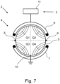
- Fig. 2 shows a second exemplary embodiment of a method 1 for determining the flow profile in the measuring tube 5 of a magnetic-inductive flow measuring device 2, the flow measuring device 2 corresponding to that in Fig. 7 flowmeter shown is designed.
- a transducer 3 and a transducer 4 the transducer 4 having a measuring tube 5, a first coil 6 for generating a first magnetic field within the measuring tube 5, a second coil 7 for generating a second magnetic field within the measuring tube, a first electrode 8 and a second electrode 9, a reference electrode 10.
- a ground ring can also be present.
- the first electrode 8 and the second electrode 9 are arranged diametrically on the measuring tube 5 for measuring a voltage occurring in the fluid and the reference electrode 10 is arranged at an angle of approximately 90 ° to the first electrode 8 and to the second electrode 9 .
- the measuring transducer has a control and evaluation unit 11.
- the first coil 6 is now energized with a first excitation current to generate a first magnetic field within the measuring tube 5.
- the second coil 7 is energized with a second excitation current 13 to generate a second magnetic field.
- the first 6 and the second coil 7 are energized in such a way that the first and the second magnetic fields are directed in opposite directions to one another.
- the in prevails within the measuring tube 5 Fig. 7 magnetic field shown.
- the measuring tube cross section can be clearly divided into four quadrants Q1 to Q4, using the in Fig. 2 Using the method shown, a vertical asymmetry between Q1 and Q3 or Q2 and Q4 can be determined.
- a first voltage E 1 is measured at the first electrode 8 against the reference potential 10 and further a second voltage E 2 is measured at the second electrode 9 against the reference potential 10 16.
- the voltages E 1 and E 2 are then evaluated to determine a vertical asymmetry of the flow profile 18. If the value of the voltage E 1 ⁇ 0, then the flow profile in the quadrants Q1 and Q3 of the left half of the measuring tube cross section is asymmetrical. If the value of the voltage E 2 ⁇ 0, the flow profile in the quadrants Q2 and Q4 of the right half of the measuring tube cross section is asymmetrical.
- Fig. 3 shows a third exemplary embodiment of a method 1 for determining the flow profile in the measuring tube 5 of a magnetic-inductive flow measuring device 2, the flow measuring device 2 having a measuring transducer 3 and a measuring sensor 4, the measuring sensor 4 having a measuring tube 5, a first coil 6 for generating a first Magnetic field within the measuring tube 5, a second coil 7 for generating a second magnetic field within the measuring tube, a first electrode 8 and a second electrode 9, a reference electrode 10.
- the first electrode 8 and the second electrode 9 are arranged diametrically on the measuring tube 5 for measuring a voltage occurring in the fluid and the reference electrode 10 is arranged at an angle of approximately 90 ° to the first electrode 8 and to the second electrode 9 .
- the measuring transducer has a control and evaluation unit 11.
- the first coil 6 is now energized with a first excitation current to generate a first magnetic field within the measuring tube 5.
- the second coil 7 is energized with a second excitation current 13 to generate a second magnetic field.
- the first 6 and the second coil 7 are energized in such a way that the first magnetic field and the second magnetic field, as in Fig. 6 shown, are aligned. This corresponds to the first measurement state M 1 of method 1.
- the voltages E 1 and E 2 are then determined 15,16.
- a next step 12 the first coil 6 is again energized and the second coil 7 is further energized 13, the coils 6, 7 now being energized in such a way that the first magnetic field and the second magnetic field, as in Fig. 7 shown are aligned in opposite directions. This corresponds to the second measurement state M 2 of method 1.
- the voltages E 1 and E 2 are then determined 15, 16. Finally, the evaluation 19 of the voltages E 1 and E 2 of the first measuring state M 1 and the second measuring state M 2 takes place for the qualitative determination of the flow profile. As part of the evaluation 19, on the one hand, by comparing the voltages E 1 and E 2 of the first measurement state M 1 , as already shown Fig. 1 described, determined whether there is a horizontal asymmetry between the left and right halves of the airfoil. In addition, how to Fig. 2 described, the voltages E 1 and E 2 of the second measuring state M 2 are evaluated to determine a vertical asymmetry.
- Fig. 4 shows a fourth exemplary embodiment of a method 1 for determining the flow profile in the measuring tube 5 of a magnetic-inductive flow measuring device 2.
- the voltages E 1 and E 2 are initially in a first measuring state M 1 , where a rectified magnetic field is present within the measuring tube 5 and then the voltages E 1 and E 2 are determined in a second measuring state M 2 , where an opposing magnetic field is present within the measuring tube 5 .
- the first coil 6 and the second coil 7 are energized again, so that a magnetic field in opposite directions is present within the measuring tube 5, each magnetic field being inverted compared to the second measuring state. This corresponds to the third measurement state M 3 .
- the voltage E 1 and the voltage E 2 are determined 15, 16.
- the flow profile is determined taking into account the voltages E 1 and E 2 of all three measuring states M 1 , M 2 and M 3 .
- Fig. 5 shows a representation of the measuring tube cross section of the measuring tube 5 through which the fluid flows, the measuring tube cross section and thus the flow profile being divided into four quadrants Q1 to Q4.
- the aforementioned flow profile types can be distinguished as follows: Type differential
- flow profile type D or F If one of the flow profile types A, B, C or E is not detected, then there is a flow profile in which one quadrant has a significantly higher or lower speed than the other three quadrants (flow profile type D or F).
- the result is a method described and illustrated with which the flow profile of a fluid flowing through a measuring tube can be determined in a spatially resolved manner. If this is taken into account when determining the flow velocity or the flow rate of the fluid, the reliability of the determination of the flow velocity or the flow rate is particularly high.
Landscapes
- Physics & Mathematics (AREA)
- Electromagnetism (AREA)
- Fluid Mechanics (AREA)
- General Physics & Mathematics (AREA)
- Engineering & Computer Science (AREA)
- Power Engineering (AREA)
- Measuring Volume Flow (AREA)
Claims (10)
- Procédé (1) de détermination du profil d'écoulement dans le tube de mesure (5) d'un débitmètre magnéto-inductif (2), le débitmètre (2) comportant au moins un convertisseur de valeurs de mesure (3) et au moins un transducteur (4), le transducteur (4) comportant au moins un tube de mesure (5), au moins une première bobine (6) destinée à générer un premier champ magnétique à l'intérieur du tube de mesure (5), au moins une deuxième bobine (7) destinée à générer un deuxième champ magnétique à l'intérieur du tube de mesure (5), au moins une première électrode (8) et au moins une deuxième électrode (9), la première électrode (8) et la deuxième électrode (9) étant disposées sur le tube de mesure (5) pour mesurer une tension apparaissant dans le fluide, et le transducteur (3) comportant au moins une unité de commande et d'évaluation (11), un moyen (10) étant prévu pour générer un potentiel de référence, le moyen de génération du potentiel de référence étant conçu comme une électrode de référence ou comme une bague de mise à la terre, la première électrode (8) et la deuxième électrode (9) étant disposées diamétralement de manière à ce que la ligne de liaison des électrodes soit disposée perpendiculairement à un champ magnétique de même sens généré par la première bobine (6) et la deuxième bobine (7) pour déterminer la vitesse d'écoulement du fluide et le procédé (1) comprenant les étapes suivantes :- alimenter (12) la première bobine (6) avec un premier courant d'excitation afin de générer un premier champ magnétique,- alimenter (13) la deuxième bobine (7) avec un deuxième courant d'excitation afin de générer un deuxième champ magnétique,- mesurer (15) une première tension E1 au niveau de la première électrode (8) par rapport au potentiel de référence,- mesurer (16) une deuxième tension E2 au niveau de la deuxième électrode (9) par rapport au potentiel de référence,caractérisé en ce que le procédé comprend les étapes suivantes :- déterminer (17, 18, 19, 20) une asymétrie verticale et/ou une asymétrie horizontale du profil d'écoulement à partir de la première valeur de mesure de tension E1 et de la deuxième valeur de mesure de tension E2,la tension tombant dans certaines sous-zones du tube de mesure ou de la section transversale d'écoulement étant mesurée séparément par rapport au potentiel de référence,différents états de mesure pouvant être générés par variation du champ magnétique à l'intérieur du tube de mesure ou des champs magnétiques générés par les bobines individuelles et le profil d'écoulement dans les différentes sous-zones dû à l'effet de différents champs magnétiques étant caractérisé par la mesure séparée des tensions E1 et E2 sur chaque électrode dans les différents états de mesure, etune pluralité de profils d'écoulement sous la forme de différents rapports de tension entre la tension El mesurée au niveau de la première électrode et la tension E2 mesurée au niveau de la deuxième électrode étant stockée dans l'unité d'évaluation avec prise en compte des différents états de mesure, eten ce que la détermination de l'asymétrie verticale et/ou de l'asymétrie horizontale du profil d'écoulement est effectuée au moyen d'une interrogation concernant ces rapports de tensions.
- Procédé (1) selon la revendication 1, caractérisé en ce que la première bobine (6) et la deuxième bobine (7) sont alimentées de manière à ce que le premier champ magnétique et le deuxième champ magnétique soient de même sens et que la détermination (17, 19, 20) de l'asymétrie horizontale du profil d'écoulement soit effectuée à partir de la comparaison de la première valeur de mesure de tension E1 et de la deuxième valeur de mesure de tension E2.
- Procédé (1) selon la revendication 1 ou 2, caractérisé en ce que la première bobine (6) et la deuxième bobine (7) sont alimentées alternativement ou chronologiquement avant ou après la génération de champs magnétiques de même sens de manière à ce que le premier champ magnétique et le deuxième champ magnétique soient dirigés dans des sens opposés et à ce que la détermination (18, 19, 20) de l'asymétrie verticale du profil d'écoulement soit effectuée à partir de la première valeur de mesure de tension E1 et de la deuxième valeur de mesure de tension E2.
- Procédé (1) selon l'une des revendications 1 à 3, caractérisé en ce que, dans un premier état de mesure M1, la première bobine (6) et la deuxième bobine (7) sont alimentées de manière à ce que le premier champ magnétique et le deuxième champ magnétique soient de même sens et qu'au moins la première valeur de mesure de tension E1 et la deuxième valeur de mesure de tension E2 soient déterminées et en ce que, dans un deuxième état de mesure M2, la première bobine (6) et la deuxième bobine (7) sont alimentées de manière à ce que le premier champ magnétique et le deuxième champ magnétique soient de sens opposés et qu'au moins la première valeur de mesure de tension E1 et la deuxième valeur de mesure de tension E2 soient déterminées, et que la détermination (17, 18, 19, 20) de l'asymétrie verticale et de l'asymétrie horizontale soit effectuée à partir des valeurs de mesure de tension E1 et E2 déterminées dans le premier état de mesure M1 et des valeurs de mesure de tension E1 et E2 déterminées dans le deuxième état de mesure M2.
- Procédé (1) selon l'une des revendications 1 à 4, caractérisé en ce que, dans un état de mesure supplémentaire, la première bobine (6) et la deuxième bobine (7) sont alimentées de manière à ce que le champ magnétique de chaque bobine (6, 7) soit inversé et que la première valeur de mesure de tension E1 et la deuxième valeur de mesure de tension E2 soient déterminées et que la première valeur de mesure de tension E1 et la deuxième valeur de mesure de tension E2 soient prises en compte lors de la détermination (20) de l'asymétrie verticale et/ou de l'asymétrie horizontale du profil d'écoulement.
- Procédé (1) selon l'une des revendications 1 à 5, caractérisé en ce que le potentiel de référence est un potentiel de masse.
- Procédé (1) selon l'une des revendications 1 à 6, caractérisé en ce que la vitesse d'écoulement v du fluide est déterminée à partir des valeurs de mesure de tension E1 et E2 mesurées avec des champs magnétiques de même sens.
- Débitmètre magnéto-inductif (2) comprenant au moins un convertisseur de valeurs de mesure (3) et au moins un transducteur (4), le transducteur (4) comportant au moins un tube de mesure (5), au moins une première bobine (6) destinée à générer un premier champ magnétique à l'intérieur du tube de mesure (5), au moins une deuxième bobine (7) destinée à générer un deuxième champ magnétique à l'intérieur du tube de mesure (5), au moins une première électrode (8) et au moins une deuxième électrode (9), la première électrode (8) et la deuxième électrode (9) étant disposées sur le tube de mesure (5) afin de mesurer une tension apparaissant dans le fluide, et le convertisseur de valeurs de mesure (3) comportant au moins une unité de commande et d'évaluation (11), un moyen (10) étant prévu pour générer un potentiel de référence, le moyen de génération du potentiel de référence étant conçu comme une électrode de référence ou comme une bague de mise à la terre, le première électrode (8) et la deuxième électrode (9) étant disposées diamétralement de manière à ce que la ligne de liaison des électrodes soit disposée perpendiculairement à un champ magnétique de même sens généré par la première bobine (6) et la deuxième bobine (7) afin de déterminer la vitesse d'écoulement du fluide,
caractérisé en ce quel'unité de commande et d'évaluation (11) est conçue de manière à déterminer en fonctionnement une asymétrie verticale et/ou une asymétrie horizontale du profil d'écoulement à partir des valeurs de mesure de tension E1 et E2 mesurées au niveau des électrodes (8, 9), les valeurs de mesure de tension E1 et E2 étant chacune mesurées par rapport au potentiel de référence,la tension tombant dans des sous-zones individuelles du tube de mesure ou dans la section transversale d'écoulement est mesurée séparément par rapport au potentiel de référence,différents états de mesure peuvent être générés par variation du champ magnétique à l'intérieur du tube de mesure ou des champs magnétiques générés par les bobines individuelles etle profil d'écoulement dans les sous-zones individuelles dû à l'effet de différents champs magnétiques étant caractérisé par la mesure séparée des tensions E1 et E2 sur chaque électrode dans les différents états de mesure, etune pluralité de profils d'écoulement sous la forme de différents rapports de tension entre la tension El mesurée au niveau de la première électrode et la tension E2 mesurée au niveau de la deuxième électrode est stockée dans l'unité d'évaluation avec prise en compte des différents états de mesure, etla détermination de l'asymétrie verticale et/ou de l'asymétrie horizontale du profil d'écoulement est effectuée au moyen d'une interrogation concernant ces rapports de tensions. - Débitmètre magnéto-inductif (2) selon la revendication 8, caractérisé en ce que le débitmètre (2) est adapté pour mettre en œuvre en fonctionnement un procédé (1) selon l'une des revendications 1 à 7.
- Utilisation d'un débitmètre magnéto-inductif (2) pour déterminer le profil d'écoulement d'un fluide qui s'écoule dans un tube de meure (5), le débitmètre (2) comprenant au moins un convertisseur de valeurs de mesure (3) et au moins un transducteur (4), le transducteur (4) comportant au moins un tube de mesure (5), au moins une première bobine (6) destinée à générer un premier champ magnétique à l'intérieur du tube de mesure (5), au moins une deuxième bobine (7) destinée à générer un deuxième champ magnétique à l'intérieur du tube de mesure (5), au moins une première électrode (8) et au moins une deuxième électrode (9), la première électrode (8) et la deuxième électrode (9) étant disposées sur le tube de mesure (5) afin de mesurer une tension apparaissant dans le fluide, et le convertisseur de valeurs de mesure (3) comportant au moins une unité de commande et d'évaluation (11), un moyen (10) étant prévu pour générer un potentiel de référence, le moyen de génération du potentiel de référence étant conçu comme une électrode de référence ou comme une bague de mise à la terre, le première électrode (8) et la deuxième électrode (9) étant disposées diamétralement de manière à ce que la ligne de liaison des électrodes soit disposée perpendiculairement à un champ magnétique de même sens généré par la première bobine (6) et la deuxième bobine (7) afin de déterminer la vitesse d'écoulement du fluide,
caractérisée en ce quel'unité de commande et d'évaluation (11) est conçue de manière à déterminer en fonctionnement une asymétrie verticale et/ou une asymétrie horizontale du profil d'écoulement à partir des valeurs de mesure de tension E1 et E2 mesurées au niveau des électrodes (8, 9), les valeurs de mesure de tension E1 et E2 étant chacune mesurées par rapport au potentiel de référence,la tension tombant dans des sous-zones individuelles du tube de mesure ou dans la section transversale d'écoulement étant mesurée séparément par rapport au potentiel de référence,différents états de mesure pouvant être générés par variation du champ magnétique à l'intérieur du tube de mesure ou des champs magnétiques générés par les bobines individuelles et le profil d'écoulement dans les sous-zones individuelles dû à l'effet de différents champs magnétiques étant caractérisé par la mesure séparée des tensions E1 et E2 sur chaque électrode dans les différents états de mesure,et une pluralité de profils d'écoulement sous la forme de différents rapports de tension entre la tension El mesurée au niveau de la première électrode et la tension E2 mesurée au niveau de la deuxième électrode étant stockée dans l'unité d'évaluation avec prise en compte des différents états de mesure, et en ce que la détermination de l'asymétrie verticale et/ou de l'asymétrie horizontale du profil d'écoulement est effectuée au moyen d'une interrogation concernant ces rapports de tensions.
Applications Claiming Priority (1)
| Application Number | Priority Date | Filing Date | Title |
|---|---|---|---|
| DE102017105547.9A DE102017105547A1 (de) | 2017-03-15 | 2017-03-15 | Verfahren zur Bestimmung des Strömungsprofils, Messwertumformer, magnetisch-induktives Durchflussmessgerät und Verwendung eines magnetisch-induktiven Durchflussmessgeräts |
Publications (2)
| Publication Number | Publication Date |
|---|---|
| EP3376176A1 EP3376176A1 (fr) | 2018-09-19 |
| EP3376176B1 true EP3376176B1 (fr) | 2024-02-28 |
Family
ID=61598933
Family Applications (1)
| Application Number | Title | Priority Date | Filing Date |
|---|---|---|---|
| EP18160483.6A Active EP3376176B1 (fr) | 2017-03-15 | 2018-03-07 | Procédé de détermination de profilé d'écoulement, transducteur, débitmètre à induction magnétique et utilisation d'un débitmètre à induction magnétique |
Country Status (4)
| Country | Link |
|---|---|
| US (1) | US10753776B2 (fr) |
| EP (1) | EP3376176B1 (fr) |
| CN (1) | CN108627206B (fr) |
| DE (1) | DE102017105547A1 (fr) |
Families Citing this family (3)
| Publication number | Priority date | Publication date | Assignee | Title |
|---|---|---|---|---|
| DE102018132935A1 (de) * | 2018-12-19 | 2020-06-25 | Endress+Hauser Flowtec Ag | Magnetisch-induktives Durchflussmessgerät und Messstelle |
| EP4067832A1 (fr) * | 2021-03-31 | 2022-10-05 | Siemens Aktiengesellschaft | Débitmètre électromagnétique comportant une pluralité de bobines |
| DE102022134109A1 (de) * | 2022-12-20 | 2024-06-20 | Endress+Hauser Flowtec Ag | Magnetisch-induktives Durchflussmessgerät |
Citations (4)
| Publication number | Priority date | Publication date | Assignee | Title |
|---|---|---|---|---|
| DE10214323C1 (de) * | 2002-03-28 | 2003-08-28 | Krohne Messtechnik Kg | Magnetisch-induktives Durchflußmeßverfahren |
| DE102007053222A1 (de) * | 2007-11-06 | 2009-05-07 | Endress + Hauser Flowtec Ag | Vorrichtung und Verfahren zur Signalverarbeitung von Spannungssignalen von Elektroden eines magnetisch induktiven Durchflussmessgeräts |
| WO2016142128A1 (fr) * | 2015-03-11 | 2016-09-15 | Endress+Hauser Flowtec Ag | Appareil magnéto-inductif de mesure de débit avec consommation réduite |
| US20200166392A1 (en) * | 2016-06-28 | 2020-05-28 | Siemens Aktiengesellschaft | Magnetically Inductive Flowmeter |
Family Cites Families (13)
| Publication number | Priority date | Publication date | Assignee | Title |
|---|---|---|---|---|
| US5280727A (en) * | 1987-09-11 | 1994-01-25 | Endress+Hauser Flowtec Ag | Electromagnetic flow measuring tube and method of making same |
| DE4330291A1 (de) | 1993-09-07 | 1995-03-09 | Fischer & Porter Gmbh | Vorrichtung zur Messung des Stroms einer ein Meßrohr durchströmenden Flüssigkeit |
| EP0770855B2 (fr) | 1995-10-20 | 2004-07-07 | Endress + Hauser (Deutschland) Holding GmbH | Débitmètre électromagnétique pour mesurer des liquides non-Newtoniens |
| US6634238B2 (en) | 2001-07-09 | 2003-10-21 | Endress + Hauser Flowtec Ag | Method of operating an electromagnetic flowmeter |
| EP1275940B1 (fr) | 2001-07-09 | 2014-04-09 | Endress + Hauser Flowtec AG | Méthode pour commander un débitmètre magnéto-inductif |
| CN100419386C (zh) * | 2001-09-20 | 2008-09-17 | 株式会社山武 | 电磁流量计 |
| DE10244646A1 (de) * | 2002-09-25 | 2004-04-08 | Ketelsen, Broder | Induktiver Durchflußmesser |
| DE10356009B4 (de) * | 2003-11-27 | 2007-10-18 | Krohne Meßtechnik GmbH & Co KG | Magnetisch-induktives Durchflußmeßgerät und Verfahren zum Betreiben eines magnetisch-induktiven Durchflußmeßgeräts |
| DE102012006891B4 (de) * | 2012-04-05 | 2019-05-23 | Krohne Ag | Magnetisch-induktives Durchflussmessgerät |
| US9021890B2 (en) * | 2012-09-26 | 2015-05-05 | Rosemount Inc. | Magnetic flowmeter with multiple coils |
| DE102015113390B4 (de) | 2015-08-13 | 2022-09-08 | Endress + Hauser Flowtec Ag | Magnetisch-induktives Durchflussmessgerät zur Ermittlung des Vorliegens eines vollausgebildeten rotationssymmetrischen Strömungsprofils |
| EP3184969A1 (fr) * | 2015-12-21 | 2017-06-28 | Proces-Data A/S | Débitmètre électromagnétique à électrodes multiples |
| CN205879281U (zh) * | 2016-08-02 | 2017-01-11 | 上海光华仪表有限公司 | 一种用于电磁流量计上的接地环 |
-
2017
- 2017-03-15 DE DE102017105547.9A patent/DE102017105547A1/de active Pending
-
2018
- 2018-03-07 EP EP18160483.6A patent/EP3376176B1/fr active Active
- 2018-03-14 US US15/920,852 patent/US10753776B2/en active Active
- 2018-03-15 CN CN201810213902.1A patent/CN108627206B/zh active Active
Patent Citations (4)
| Publication number | Priority date | Publication date | Assignee | Title |
|---|---|---|---|---|
| DE10214323C1 (de) * | 2002-03-28 | 2003-08-28 | Krohne Messtechnik Kg | Magnetisch-induktives Durchflußmeßverfahren |
| DE102007053222A1 (de) * | 2007-11-06 | 2009-05-07 | Endress + Hauser Flowtec Ag | Vorrichtung und Verfahren zur Signalverarbeitung von Spannungssignalen von Elektroden eines magnetisch induktiven Durchflussmessgeräts |
| WO2016142128A1 (fr) * | 2015-03-11 | 2016-09-15 | Endress+Hauser Flowtec Ag | Appareil magnéto-inductif de mesure de débit avec consommation réduite |
| US20200166392A1 (en) * | 2016-06-28 | 2020-05-28 | Siemens Aktiengesellschaft | Magnetically Inductive Flowmeter |
Also Published As
| Publication number | Publication date |
|---|---|
| EP3376176A1 (fr) | 2018-09-19 |
| CN108627206B (zh) | 2020-11-17 |
| US20180266859A1 (en) | 2018-09-20 |
| DE102017105547A1 (de) | 2018-09-20 |
| CN108627206A (zh) | 2018-10-09 |
| US10753776B2 (en) | 2020-08-25 |
Similar Documents
| Publication | Publication Date | Title |
|---|---|---|
| EP3335016B1 (fr) | Débitmètre magnéto-inductif et procédé de compensation d'une erreur de mesure induite par un débit | |
| DE102015116771B4 (de) | Verfahren zum Einstellen einer konstanten Magnetfeldstärke eines Magnetfelds bei einem magnetisch-induktiven Durchflussmessgerät und diesbezügliches magnetisch-induktives Durchflussmessgerät | |
| EP3775791B1 (fr) | Compteur de débit magnetique-inductif et unité de mesure comportant un tel compteur de débit magnetique-inductif | |
| EP2981833A1 (fr) | Résistance de mesure et procédé de mesure correspondant | |
| EP1536211B1 (fr) | Procédé pour faire fonctionner un débitmètre magnéto-inductif | |
| DE10064738A1 (de) | Meßgerät und Verfahren zur Prüfung des Meßbetriebs eines Meßgeräts | |
| EP3293499B1 (fr) | Procédé de fonctionnement d'un débitmètre magnétique inductif et débitmètre magnétique inductif | |
| EP3376176B1 (fr) | Procédé de détermination de profilé d'écoulement, transducteur, débitmètre à induction magnétique et utilisation d'un débitmètre à induction magnétique | |
| WO2016041723A1 (fr) | Débitmètre à induction magnétique pourvu d'un système magnétique à quatre bobines | |
| DE102020123945B4 (de) | Verfahren zum Betreiben eines magnetisch-induktiven Durchflussmessgeräts und entsprechendes magnetisch-induktives Durchflussmessgerät | |
| DE102015120103B4 (de) | Verfahren zur Durchflussmessung durch ein magnetisch-induktives Durchflussmessgerät | |
| EP0770855B2 (fr) | Débitmètre électromagnétique pour mesurer des liquides non-Newtoniens | |
| EP3211384A2 (fr) | Débitmètre à induction magnétique et procédé associé | |
| EP3891475B1 (fr) | Débitmètre magnetique inductif | |
| DE102005028723A1 (de) | Magnetisch-induktives Durchflussmessgerät | |
| DE112018000081T5 (de) | Durchflussmesser | |
| EP1275940A2 (fr) | Méthode pour commander un débitmètre magnéto-inductif | |
| DE102013103211A1 (de) | Magnetisch-induktives Durchflussmessgerät | |
| DE102013014016B4 (de) | Verfahren zum Betreiben eines magnetisch-induktiven Durchflussmessgeräts | |
| EP4071447A1 (fr) | Procédé de détermination de la conductivité d'un milieu, procédé de fonctionnement d'un débitmètre à induction magnétique, et débitmètre à induction magnétique | |
| EP4004496B1 (fr) | Débitmètre à induction magnétique et procédé de fonctionnement d'un débitmètre à induction magnétique | |
| EP4449064B1 (fr) | Procédé de détermination du niveau de remplissage d'un tuyau, unité d'évaluation, système de mesure de débit et produit-programme informatique | |
| EP4428500B1 (fr) | Procédé de fonctionnement d'un débitmètre à induction magnétique et débitmètre à induction magnétique | |
| DE102019108985A1 (de) | Magnetisch-induktives Durchflussmessgerät | |
| EP4296628B1 (fr) | Débitmètre magnéto-inductif |
Legal Events
| Date | Code | Title | Description |
|---|---|---|---|
| PUAI | Public reference made under article 153(3) epc to a published international application that has entered the european phase |
Free format text: ORIGINAL CODE: 0009012 |
|
| STAA | Information on the status of an ep patent application or granted ep patent |
Free format text: STATUS: THE APPLICATION HAS BEEN PUBLISHED |
|
| AK | Designated contracting states |
Kind code of ref document: A1 Designated state(s): AL AT BE BG CH CY CZ DE DK EE ES FI FR GB GR HR HU IE IS IT LI LT LU LV MC MK MT NL NO PL PT RO RS SE SI SK SM TR |
|
| AX | Request for extension of the european patent |
Extension state: BA ME |
|
| STAA | Information on the status of an ep patent application or granted ep patent |
Free format text: STATUS: REQUEST FOR EXAMINATION WAS MADE |
|
| 17P | Request for examination filed |
Effective date: 20190313 |
|
| RBV | Designated contracting states (corrected) |
Designated state(s): AL AT BE BG CH CY CZ DE DK EE ES FI FR GB GR HR HU IE IS IT LI LT LU LV MC MK MT NL NO PL PT RO RS SE SI SK SM TR |
|
| STAA | Information on the status of an ep patent application or granted ep patent |
Free format text: STATUS: EXAMINATION IS IN PROGRESS |
|
| 17Q | First examination report despatched |
Effective date: 20210127 |
|
| GRAJ | Information related to disapproval of communication of intention to grant by the applicant or resumption of examination proceedings by the epo deleted |
Free format text: ORIGINAL CODE: EPIDOSDIGR1 |
|
| GRAP | Despatch of communication of intention to grant a patent |
Free format text: ORIGINAL CODE: EPIDOSNIGR1 |
|
| GRAP | Despatch of communication of intention to grant a patent |
Free format text: ORIGINAL CODE: EPIDOSNIGR1 |
|
| STAA | Information on the status of an ep patent application or granted ep patent |
Free format text: STATUS: GRANT OF PATENT IS INTENDED |
|
| INTG | Intention to grant announced |
Effective date: 20231004 |
|
| INTG | Intention to grant announced |
Effective date: 20231012 |
|
| GRAS | Grant fee paid |
Free format text: ORIGINAL CODE: EPIDOSNIGR3 |
|
| GRAA | (expected) grant |
Free format text: ORIGINAL CODE: 0009210 |
|
| STAA | Information on the status of an ep patent application or granted ep patent |
Free format text: STATUS: THE PATENT HAS BEEN GRANTED |
|
| AK | Designated contracting states |
Kind code of ref document: B1 Designated state(s): AL AT BE BG CH CY CZ DE DK EE ES FI FR GB GR HR HU IE IS IT LI LT LU LV MC MK MT NL NO PL PT RO RS SE SI SK SM TR |
|
| REG | Reference to a national code |
Ref country code: GB Ref legal event code: FG4D Free format text: NOT ENGLISH |
|
| REG | Reference to a national code |
Ref country code: CH Ref legal event code: EP |
|
| REG | Reference to a national code |
Ref country code: DE Ref legal event code: R096 Ref document number: 502018014157 Country of ref document: DE |
|
| REG | Reference to a national code |
Ref country code: IE Ref legal event code: FG4D Free format text: LANGUAGE OF EP DOCUMENT: GERMAN |
|
| P01 | Opt-out of the competence of the unified patent court (upc) registered |
Effective date: 20240301 |
|
| REG | Reference to a national code |
Ref country code: LT Ref legal event code: MG9D |
|
| REG | Reference to a national code |
Ref country code: NL Ref legal event code: FP |
|
| PG25 | Lapsed in a contracting state [announced via postgrant information from national office to epo] |
Ref country code: IS Free format text: LAPSE BECAUSE OF FAILURE TO SUBMIT A TRANSLATION OF THE DESCRIPTION OR TO PAY THE FEE WITHIN THE PRESCRIBED TIME-LIMIT Effective date: 20240628 |
|
| PG25 | Lapsed in a contracting state [announced via postgrant information from national office to epo] |
Ref country code: LT Free format text: LAPSE BECAUSE OF FAILURE TO SUBMIT A TRANSLATION OF THE DESCRIPTION OR TO PAY THE FEE WITHIN THE PRESCRIBED TIME-LIMIT Effective date: 20240228 |
|
| PG25 | Lapsed in a contracting state [announced via postgrant information from national office to epo] |
Ref country code: GR Free format text: LAPSE BECAUSE OF FAILURE TO SUBMIT A TRANSLATION OF THE DESCRIPTION OR TO PAY THE FEE WITHIN THE PRESCRIBED TIME-LIMIT Effective date: 20240529 |
|
| PG25 | Lapsed in a contracting state [announced via postgrant information from national office to epo] |
Ref country code: HR Free format text: LAPSE BECAUSE OF FAILURE TO SUBMIT A TRANSLATION OF THE DESCRIPTION OR TO PAY THE FEE WITHIN THE PRESCRIBED TIME-LIMIT Effective date: 20240228 Ref country code: RS Free format text: LAPSE BECAUSE OF FAILURE TO SUBMIT A TRANSLATION OF THE DESCRIPTION OR TO PAY THE FEE WITHIN THE PRESCRIBED TIME-LIMIT Effective date: 20240528 |
|
| PG25 | Lapsed in a contracting state [announced via postgrant information from national office to epo] |
Ref country code: ES Free format text: LAPSE BECAUSE OF FAILURE TO SUBMIT A TRANSLATION OF THE DESCRIPTION OR TO PAY THE FEE WITHIN THE PRESCRIBED TIME-LIMIT Effective date: 20240228 |
|
| PG25 | Lapsed in a contracting state [announced via postgrant information from national office to epo] |
Ref country code: RS Free format text: LAPSE BECAUSE OF FAILURE TO SUBMIT A TRANSLATION OF THE DESCRIPTION OR TO PAY THE FEE WITHIN THE PRESCRIBED TIME-LIMIT Effective date: 20240528 Ref country code: NO Free format text: LAPSE BECAUSE OF FAILURE TO SUBMIT A TRANSLATION OF THE DESCRIPTION OR TO PAY THE FEE WITHIN THE PRESCRIBED TIME-LIMIT Effective date: 20240528 Ref country code: LT Free format text: LAPSE BECAUSE OF FAILURE TO SUBMIT A TRANSLATION OF THE DESCRIPTION OR TO PAY THE FEE WITHIN THE PRESCRIBED TIME-LIMIT Effective date: 20240228 Ref country code: IS Free format text: LAPSE BECAUSE OF FAILURE TO SUBMIT A TRANSLATION OF THE DESCRIPTION OR TO PAY THE FEE WITHIN THE PRESCRIBED TIME-LIMIT Effective date: 20240628 Ref country code: HR Free format text: LAPSE BECAUSE OF FAILURE TO SUBMIT A TRANSLATION OF THE DESCRIPTION OR TO PAY THE FEE WITHIN THE PRESCRIBED TIME-LIMIT Effective date: 20240228 Ref country code: GR Free format text: LAPSE BECAUSE OF FAILURE TO SUBMIT A TRANSLATION OF THE DESCRIPTION OR TO PAY THE FEE WITHIN THE PRESCRIBED TIME-LIMIT Effective date: 20240529 Ref country code: FI Free format text: LAPSE BECAUSE OF FAILURE TO SUBMIT A TRANSLATION OF THE DESCRIPTION OR TO PAY THE FEE WITHIN THE PRESCRIBED TIME-LIMIT Effective date: 20240228 Ref country code: ES Free format text: LAPSE BECAUSE OF FAILURE TO SUBMIT A TRANSLATION OF THE DESCRIPTION OR TO PAY THE FEE WITHIN THE PRESCRIBED TIME-LIMIT Effective date: 20240228 Ref country code: BG Free format text: LAPSE BECAUSE OF FAILURE TO SUBMIT A TRANSLATION OF THE DESCRIPTION OR TO PAY THE FEE WITHIN THE PRESCRIBED TIME-LIMIT Effective date: 20240228 |
|
| PG25 | Lapsed in a contracting state [announced via postgrant information from national office to epo] |
Ref country code: PL Free format text: LAPSE BECAUSE OF FAILURE TO SUBMIT A TRANSLATION OF THE DESCRIPTION OR TO PAY THE FEE WITHIN THE PRESCRIBED TIME-LIMIT Effective date: 20240228 Ref country code: PT Free format text: LAPSE BECAUSE OF FAILURE TO SUBMIT A TRANSLATION OF THE DESCRIPTION OR TO PAY THE FEE WITHIN THE PRESCRIBED TIME-LIMIT Effective date: 20240628 |
|
| PG25 | Lapsed in a contracting state [announced via postgrant information from national office to epo] |
Ref country code: SE Free format text: LAPSE BECAUSE OF FAILURE TO SUBMIT A TRANSLATION OF THE DESCRIPTION OR TO PAY THE FEE WITHIN THE PRESCRIBED TIME-LIMIT Effective date: 20240228 Ref country code: PT Free format text: LAPSE BECAUSE OF FAILURE TO SUBMIT A TRANSLATION OF THE DESCRIPTION OR TO PAY THE FEE WITHIN THE PRESCRIBED TIME-LIMIT Effective date: 20240628 Ref country code: PL Free format text: LAPSE BECAUSE OF FAILURE TO SUBMIT A TRANSLATION OF THE DESCRIPTION OR TO PAY THE FEE WITHIN THE PRESCRIBED TIME-LIMIT Effective date: 20240228 Ref country code: LV Free format text: LAPSE BECAUSE OF FAILURE TO SUBMIT A TRANSLATION OF THE DESCRIPTION OR TO PAY THE FEE WITHIN THE PRESCRIBED TIME-LIMIT Effective date: 20240228 |
|
| PG25 | Lapsed in a contracting state [announced via postgrant information from national office to epo] |
Ref country code: DK Free format text: LAPSE BECAUSE OF FAILURE TO SUBMIT A TRANSLATION OF THE DESCRIPTION OR TO PAY THE FEE WITHIN THE PRESCRIBED TIME-LIMIT Effective date: 20240228 |
|
| PG25 | Lapsed in a contracting state [announced via postgrant information from national office to epo] |
Ref country code: SM Free format text: LAPSE BECAUSE OF FAILURE TO SUBMIT A TRANSLATION OF THE DESCRIPTION OR TO PAY THE FEE WITHIN THE PRESCRIBED TIME-LIMIT Effective date: 20240228 |
|
| PG25 | Lapsed in a contracting state [announced via postgrant information from national office to epo] |
Ref country code: CZ Free format text: LAPSE BECAUSE OF FAILURE TO SUBMIT A TRANSLATION OF THE DESCRIPTION OR TO PAY THE FEE WITHIN THE PRESCRIBED TIME-LIMIT Effective date: 20240228 Ref country code: EE Free format text: LAPSE BECAUSE OF FAILURE TO SUBMIT A TRANSLATION OF THE DESCRIPTION OR TO PAY THE FEE WITHIN THE PRESCRIBED TIME-LIMIT Effective date: 20240228 |
|
| PG25 | Lapsed in a contracting state [announced via postgrant information from national office to epo] |
Ref country code: SK Free format text: LAPSE BECAUSE OF FAILURE TO SUBMIT A TRANSLATION OF THE DESCRIPTION OR TO PAY THE FEE WITHIN THE PRESCRIBED TIME-LIMIT Effective date: 20240228 |
|
| PG25 | Lapsed in a contracting state [announced via postgrant information from national office to epo] |
Ref country code: SM Free format text: LAPSE BECAUSE OF FAILURE TO SUBMIT A TRANSLATION OF THE DESCRIPTION OR TO PAY THE FEE WITHIN THE PRESCRIBED TIME-LIMIT Effective date: 20240228 Ref country code: SK Free format text: LAPSE BECAUSE OF FAILURE TO SUBMIT A TRANSLATION OF THE DESCRIPTION OR TO PAY THE FEE WITHIN THE PRESCRIBED TIME-LIMIT Effective date: 20240228 Ref country code: RO Free format text: LAPSE BECAUSE OF FAILURE TO SUBMIT A TRANSLATION OF THE DESCRIPTION OR TO PAY THE FEE WITHIN THE PRESCRIBED TIME-LIMIT Effective date: 20240228 Ref country code: EE Free format text: LAPSE BECAUSE OF FAILURE TO SUBMIT A TRANSLATION OF THE DESCRIPTION OR TO PAY THE FEE WITHIN THE PRESCRIBED TIME-LIMIT Effective date: 20240228 Ref country code: DK Free format text: LAPSE BECAUSE OF FAILURE TO SUBMIT A TRANSLATION OF THE DESCRIPTION OR TO PAY THE FEE WITHIN THE PRESCRIBED TIME-LIMIT Effective date: 20240228 Ref country code: CZ Free format text: LAPSE BECAUSE OF FAILURE TO SUBMIT A TRANSLATION OF THE DESCRIPTION OR TO PAY THE FEE WITHIN THE PRESCRIBED TIME-LIMIT Effective date: 20240228 |
|
| PG25 | Lapsed in a contracting state [announced via postgrant information from national office to epo] |
Ref country code: LU Free format text: LAPSE BECAUSE OF NON-PAYMENT OF DUE FEES Effective date: 20240307 |
|
| PG25 | Lapsed in a contracting state [announced via postgrant information from national office to epo] |
Ref country code: MC Free format text: LAPSE BECAUSE OF FAILURE TO SUBMIT A TRANSLATION OF THE DESCRIPTION OR TO PAY THE FEE WITHIN THE PRESCRIBED TIME-LIMIT Effective date: 20240228 |
|
| PG25 | Lapsed in a contracting state [announced via postgrant information from national office to epo] |
Ref country code: MC Free format text: LAPSE BECAUSE OF FAILURE TO SUBMIT A TRANSLATION OF THE DESCRIPTION OR TO PAY THE FEE WITHIN THE PRESCRIBED TIME-LIMIT Effective date: 20240228 Ref country code: LU Free format text: LAPSE BECAUSE OF NON-PAYMENT OF DUE FEES Effective date: 20240307 |
|
| REG | Reference to a national code |
Ref country code: DE Ref legal event code: R097 Ref document number: 502018014157 Country of ref document: DE |
|
| PG25 | Lapsed in a contracting state [announced via postgrant information from national office to epo] |
Ref country code: IT Free format text: LAPSE BECAUSE OF FAILURE TO SUBMIT A TRANSLATION OF THE DESCRIPTION OR TO PAY THE FEE WITHIN THE PRESCRIBED TIME-LIMIT Effective date: 20240228 |
|
| REG | Reference to a national code |
Ref country code: BE Ref legal event code: MM Effective date: 20240331 |
|
| PG25 | Lapsed in a contracting state [announced via postgrant information from national office to epo] |
Ref country code: IT Free format text: LAPSE BECAUSE OF FAILURE TO SUBMIT A TRANSLATION OF THE DESCRIPTION OR TO PAY THE FEE WITHIN THE PRESCRIBED TIME-LIMIT Effective date: 20240228 |
|
| PLBE | No opposition filed within time limit |
Free format text: ORIGINAL CODE: 0009261 |
|
| STAA | Information on the status of an ep patent application or granted ep patent |
Free format text: STATUS: NO OPPOSITION FILED WITHIN TIME LIMIT |
|
| PG25 | Lapsed in a contracting state [announced via postgrant information from national office to epo] |
Ref country code: BE Free format text: LAPSE BECAUSE OF NON-PAYMENT OF DUE FEES Effective date: 20240331 |
|
| PG25 | Lapsed in a contracting state [announced via postgrant information from national office to epo] |
Ref country code: IE Free format text: LAPSE BECAUSE OF NON-PAYMENT OF DUE FEES Effective date: 20240307 |
|
| GBPC | Gb: european patent ceased through non-payment of renewal fee |
Effective date: 20240528 |
|
| PG25 | Lapsed in a contracting state [announced via postgrant information from national office to epo] |
Ref country code: IE Free format text: LAPSE BECAUSE OF NON-PAYMENT OF DUE FEES Effective date: 20240307 Ref country code: BE Free format text: LAPSE BECAUSE OF NON-PAYMENT OF DUE FEES Effective date: 20240331 |
|
| 26N | No opposition filed |
Effective date: 20241129 |
|
| PG25 | Lapsed in a contracting state [announced via postgrant information from national office to epo] |
Ref country code: SI Free format text: LAPSE BECAUSE OF FAILURE TO SUBMIT A TRANSLATION OF THE DESCRIPTION OR TO PAY THE FEE WITHIN THE PRESCRIBED TIME-LIMIT Effective date: 20240228 |
|
| PG25 | Lapsed in a contracting state [announced via postgrant information from national office to epo] |
Ref country code: GB Free format text: LAPSE BECAUSE OF NON-PAYMENT OF DUE FEES Effective date: 20240528 |
|
| REG | Reference to a national code |
Ref country code: AT Ref legal event code: MM01 Ref document number: 1661638 Country of ref document: AT Kind code of ref document: T Effective date: 20240307 |
|
| PGFP | Annual fee paid to national office [announced via postgrant information from national office to epo] |
Ref country code: DE Payment date: 20250515 Year of fee payment: 8 |
|
| PGFP | Annual fee paid to national office [announced via postgrant information from national office to epo] |
Ref country code: CH Payment date: 20250401 Year of fee payment: 8 |
|
| PG25 | Lapsed in a contracting state [announced via postgrant information from national office to epo] |
Ref country code: AT Free format text: LAPSE BECAUSE OF NON-PAYMENT OF DUE FEES Effective date: 20240307 |
|
| PG25 | Lapsed in a contracting state [announced via postgrant information from national office to epo] |
Ref country code: CY Free format text: LAPSE BECAUSE OF FAILURE TO SUBMIT A TRANSLATION OF THE DESCRIPTION OR TO PAY THE FEE WITHIN THE PRESCRIBED TIME-LIMIT; INVALID AB INITIO Effective date: 20180307 |
|
| PG25 | Lapsed in a contracting state [announced via postgrant information from national office to epo] |
Ref country code: HU Free format text: LAPSE BECAUSE OF FAILURE TO SUBMIT A TRANSLATION OF THE DESCRIPTION OR TO PAY THE FEE WITHIN THE PRESCRIBED TIME-LIMIT; INVALID AB INITIO Effective date: 20180307 |
|
| PG25 | Lapsed in a contracting state [announced via postgrant information from national office to epo] |
Ref country code: TR Free format text: LAPSE BECAUSE OF FAILURE TO SUBMIT A TRANSLATION OF THE DESCRIPTION OR TO PAY THE FEE WITHIN THE PRESCRIBED TIME-LIMIT Effective date: 20240228 |
|
| REG | Reference to a national code |
Ref country code: CH Ref legal event code: U11 Free format text: ST27 STATUS EVENT CODE: U-0-0-U10-U11 (AS PROVIDED BY THE NATIONAL OFFICE) Effective date: 20260401 |
|
| PGFP | Annual fee paid to national office [announced via postgrant information from national office to epo] |
Ref country code: NL Payment date: 20260319 Year of fee payment: 9 |
|
| PGFP | Annual fee paid to national office [announced via postgrant information from national office to epo] |
Ref country code: FR Payment date: 20260320 Year of fee payment: 9 |