EP2734762B1 - Elektromagnetische ventilmontage für fahrzeugsitz - Google Patents
Elektromagnetische ventilmontage für fahrzeugsitz Download PDFInfo
- Publication number
- EP2734762B1 EP2734762B1 EP11757409.5A EP11757409A EP2734762B1 EP 2734762 B1 EP2734762 B1 EP 2734762B1 EP 11757409 A EP11757409 A EP 11757409A EP 2734762 B1 EP2734762 B1 EP 2734762B1
- Authority
- EP
- European Patent Office
- Prior art keywords
- plunger
- dampener
- support
- solenoid valve
- valve assembly
- Prior art date
- Legal status (The legal status is an assumption and is not a legal conclusion. Google has not performed a legal analysis and makes no representation as to the accuracy of the status listed.)
- Active
Links
Images





Classifications
-
- F—MECHANICAL ENGINEERING; LIGHTING; HEATING; WEAPONS; BLASTING
- F16—ENGINEERING ELEMENTS AND UNITS; GENERAL MEASURES FOR PRODUCING AND MAINTAINING EFFECTIVE FUNCTIONING OF MACHINES OR INSTALLATIONS; THERMAL INSULATION IN GENERAL
- F16K—VALVES; TAPS; COCKS; ACTUATING-FLOATS; DEVICES FOR VENTING OR AERATING
- F16K31/00—Actuating devices; Operating means; Releasing devices
- F16K31/02—Actuating devices; Operating means; Releasing devices electric; magnetic
- F16K31/06—Actuating devices; Operating means; Releasing devices electric; magnetic using a magnet, e.g. diaphragm valves, cutting off by means of a liquid
- F16K31/0686—Braking, pressure equilibration, shock absorbing
- F16K31/0696—Shock absorbing, e.g. using a dash-pot
-
- F—MECHANICAL ENGINEERING; LIGHTING; HEATING; WEAPONS; BLASTING
- F16—ENGINEERING ELEMENTS AND UNITS; GENERAL MEASURES FOR PRODUCING AND MAINTAINING EFFECTIVE FUNCTIONING OF MACHINES OR INSTALLATIONS; THERMAL INSULATION IN GENERAL
- F16K—VALVES; TAPS; COCKS; ACTUATING-FLOATS; DEVICES FOR VENTING OR AERATING
- F16K27/00—Construction of housing; Use of materials therefor
- F16K27/02—Construction of housing; Use of materials therefor of lift valves
- F16K27/029—Electromagnetically actuated valves
-
- B—PERFORMING OPERATIONS; TRANSPORTING
- B60—VEHICLES IN GENERAL
- B60N—SEATS SPECIALLY ADAPTED FOR VEHICLES; VEHICLE PASSENGER ACCOMMODATION NOT OTHERWISE PROVIDED FOR
- B60N2/00—Seats specially adapted for vehicles; Arrangement or mounting of seats in vehicles
- B60N2/70—Upholstery springs ; Upholstery
- B60N2/7023—Coach-like constructions
- B60N2/7035—Cushions
- B60N2/7047—Springs
- B60N2/7082—Springs with air or fluid cushions
-
- B—PERFORMING OPERATIONS; TRANSPORTING
- B60—VEHICLES IN GENERAL
- B60N—SEATS SPECIALLY ADAPTED FOR VEHICLES; VEHICLE PASSENGER ACCOMMODATION NOT OTHERWISE PROVIDED FOR
- B60N2/00—Seats specially adapted for vehicles; Arrangement or mounting of seats in vehicles
- B60N2/90—Details or parts not otherwise provided for
- B60N2/914—Hydro-pneumatic adjustments of the shape
-
- F—MECHANICAL ENGINEERING; LIGHTING; HEATING; WEAPONS; BLASTING
- F16—ENGINEERING ELEMENTS AND UNITS; GENERAL MEASURES FOR PRODUCING AND MAINTAINING EFFECTIVE FUNCTIONING OF MACHINES OR INSTALLATIONS; THERMAL INSULATION IN GENERAL
- F16K—VALVES; TAPS; COCKS; ACTUATING-FLOATS; DEVICES FOR VENTING OR AERATING
- F16K31/00—Actuating devices; Operating means; Releasing devices
- F16K31/02—Actuating devices; Operating means; Releasing devices electric; magnetic
- F16K31/06—Actuating devices; Operating means; Releasing devices electric; magnetic using a magnet, e.g. diaphragm valves, cutting off by means of a liquid
- F16K31/0644—One-way valve
- F16K31/0655—Lift valves
- F16K31/0658—Armature and valve member being one single element
-
- F—MECHANICAL ENGINEERING; LIGHTING; HEATING; WEAPONS; BLASTING
- F16—ENGINEERING ELEMENTS AND UNITS; GENERAL MEASURES FOR PRODUCING AND MAINTAINING EFFECTIVE FUNCTIONING OF MACHINES OR INSTALLATIONS; THERMAL INSULATION IN GENERAL
- F16K—VALVES; TAPS; COCKS; ACTUATING-FLOATS; DEVICES FOR VENTING OR AERATING
- F16K31/00—Actuating devices; Operating means; Releasing devices
- F16K31/02—Actuating devices; Operating means; Releasing devices electric; magnetic
- F16K31/06—Actuating devices; Operating means; Releasing devices electric; magnetic using a magnet, e.g. diaphragm valves, cutting off by means of a liquid
- F16K31/0686—Braking, pressure equilibration, shock absorbing
-
- H—ELECTRICITY
- H01—ELECTRIC ELEMENTS
- H01F—MAGNETS; INDUCTANCES; TRANSFORMERS; SELECTION OF MATERIALS FOR THEIR MAGNETIC PROPERTIES
- H01F7/00—Magnets
- H01F7/06—Electromagnets; Actuators including electromagnets
- H01F7/08—Electromagnets; Actuators including electromagnets with armatures
- H01F7/088—Electromagnets; Actuators including electromagnets with armatures provided with means for absorbing shocks
-
- H—ELECTRICITY
- H01—ELECTRIC ELEMENTS
- H01F—MAGNETS; INDUCTANCES; TRANSFORMERS; SELECTION OF MATERIALS FOR THEIR MAGNETIC PROPERTIES
- H01F7/00—Magnets
- H01F7/06—Electromagnets; Actuators including electromagnets
- H01F7/08—Electromagnets; Actuators including electromagnets with armatures
- H01F7/16—Rectilinearly-movable armatures
- H01F7/1607—Armatures entering the winding
Definitions
- the present invention relates to a seat assembly for a vehicle, and more specifically to a solenoid valve assembly for a seat of a vehicle.
- Solenoids are known in the art. Some solenoids include a plunger movable in response to a magnetic field. A common problem with solenoids having plungers is undesired noise. Therefore, various designs have been developed to try to reduce undesirable noise. For example, one such type of solenoid is disclosed in United States Patent No. 5,663,700 (the '700 patent) to Spence et al. The '700 patent discloses a solenoid including a plunger movable through a tube. A pair of wear bands are disposed about a periphery of the plunger. The wear bands form a seal with a tube wall of the tube.
- the wear bands engage the tube wall as the plunger moves which creates frictional forces that must be overcome to move the plunger to a desired position. Further, movement of the plunger is reduced due to the frictional forces.
- an air bleed passage in the wear bands allow air to pass therethrough which decreases acceleration of the plunger, and thus delays movement of the plunger to the desired position.
- EP 2045496 A1 to Cartier Technologies G WO 2007/088403 A1 to BorgWarner Inc., U.S. Pat. Pub. No. 2007/069145 A1 to Juergen et al. , and U.S. Pat. No. 3,446,473 to Barker each generally disclose solenoid valve assemblies that include movable plungers that allow fluid flow within a gap and a coil for controlling the relative positioning of the plunger.
- Each of these references also generally disclose one or more dampeners to prevent the direct engagement between the plunger and a support as the plunger moves to prevent or limit noise during operation.
- the one or more dampeners are configured such that they are always in contact with both the plunger and the support, and hence such continuous contact prevents the free movement of the plunger between a first and second position as the coil is energized or deenergized.
- the present invention provides for a solenoid valve assembly including a housing defining a cavity and a support disposed in the cavity.
- the support defines a bore along a longitudinal axis.
- the solenoid valve assembly further includes a coil disposed about the support and defining an energized state for generating a magnetic field and a de-energized state.
- the solenoid valve assembly also includes a plunger movably disposed in the bore of the support between a first position engaging the housing and a second position spaced from the housing. The plunger is radially spaced from the support relative to the longitudinal axis to define a gap between the plunger and the support.
- the solenoid valve assembly further includes a dampener coupled to one of the support and the plunger adjacent the gap to prevent direct engagement between the support and the plunger as the plunger moves between the first and second positions during the energized and de-energized states for reducing noise during operation.
- the present invention provides for a first dampener preventing direct engagement between the support and the plunger as the plunger moves for reducing noise during movement of the plunger.
- the first dampener prevents direct engagement between the support and the plunger as the plunger moves for maintaining a gap between the plunger and the support which allows the plunger to move more freely than the plunger design as discussed in the Background of the Invention section.
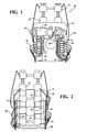
- a seat assembly 20 for a vehicle (not shown) is generally shown in Figure 1 .
- the seat assembly 20 includes a seat frame 22.
- the seat assembly 20 can include a seat with the seat frame 22 disposed in the seat. More specifically, the seat can include a back portion for supporting a user's back and a bottom portion for supporting the user's legs.
- the seat frame 22 can be disposed in the back portion and/or the bottom portion of the seat. It is to be appreciated that the seat frame 22 can be any suitable configuration.
- the seat assembly 20 includes a bladder 24 coupled to the seat frame 22.
- the bladder 24 defines an inflate position with the bladder 24 inflated and a deflate position with the bladder 24 deflated. It is to be appreciated that the bladder 24 can be partially inflated and partially deflated. Hence, the inflate position is defined as the bladder 24 being partially inflated or fully inflated and the deflate position is defined as the bladder 24 being partially deflated or fully deflated. It is to be appreciated that the bladder 24 can be coupled to the seat frame 22, the back portion, the bottom portion, or any other suitable location of the seat.
- the seat assembly 20 can further include a pump 26 mounted to the seat frame 22 for supplying fluid to the bladder 24 to inflate the bladder 24 to the inflate position.
- the pump 26 is activated for supplying fluid to the bladder 24.
- the fluid can be defined as air or any other suitable fluid.
- a plurality of tubes 28 can be utilized to couple together various components for guiding the fluid from the pump 26.
- tube(s) 28 can be coupled to the bladder 24 and/or the pump 26 for guiding the fluid from the pump 26 to the bladder 24.
- the seat assembly 20 further includes a solenoid valve assembly 30 mounted to the seat frame 22 and coupled to the bladder 24.
- the solenoid valve assembly 30 can be for the seat of the vehicle.
- the solenoid valve assembly 30 controls the flow of the fluid to the bladder 24.
- the solenoid valve assembly 30 controls when the bladder 24 is inflated to the inflate position and when the bladder 24 is deflated to the deflate position. Further, the solenoid valve assembly 30 controls when the bladder 24 is partially inflated and partially deflated.
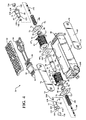
- the solenoid valve assembly 30 includes a housing 32 defining a cavity 34.
- the housing 32 is mounted to the seat frame 22 for securing the solenoid valve assembly 30 to the seat frame 22.
- the bladder 24 is coupled to the housing 32.
- at least one of the tubes 28 is attached to the housing 32 and the bladder 24 such that the tube(s) 28 couples the housing 32 to the bladder 24.
- the bladder 24 is attached directly to the housing 32.
- the housing 32 includes a first port 36 defining a first aperture 38 adjacent the cavity 34. More specifically, the first aperture 38 is in fluid communication with the cavity 34. Fluid flows into the cavity 34 of the housing 32 through the first port 36.
- at least one tube 28 is coupled to the first port 36 for guiding fluid from the pump 26 to the first port 36. As such, when a user desires to inflate the bladder 24, fluid is allowed to flow in through the first port 36 and into the cavity 34.
- the housing 32 includes a second port 40 adjacent the cavity 34 and spaced from the first port 36.
- the bladder 24 is coupled to the second port 40 with the second port 40 defining a second aperture 42 in fluid communication with the cavity 34 and the bladder 24 for inflating the bladder 24 to the inflate position and deflating the bladder 24 to the deflate position.
- the first and second apertures 38, 42 are in fluid communication with each other.
- the housing 32 includes a third port 44 defining a third aperture 46 adjacent the cavity 34. More specifically, the third aperture 46 is in fluid communication with the cavity 34. As such, the first, second, and third apertures 38, 42, 46 are in fluid communication with each other. Fluid flows out of the cavity 34 and out of the bladder 24 through the third port 44. For example, when the user desires to deflate the bladder 24, fluid is allowed to flow out of the cavity 34, the second port 40, and the third port 44.
- the solenoid valve assembly 30 also includes a support 48 disposed in the cavity 34.
- the support 48 defines a bore 50 and a recess 52 spaced from the bore 50.
- the bore 50 is disposed along a longitudinal axis L with the recess 52 being radially spaced relative to the longitudinal axis L.
- the recess 52 can be further defined as a plurality of recesses 52 spaced from each other relative to the longitudinal axis L. Specifically, one of the recesses 52 can be disposed adjacent one end of the support 48 and another one of the recesses 52 can be disposed adjacent another end of the support 48.
- the support 48 is further defined as a first support 48
- the bore 50 is further defined as a first bore 50
- the recess 52 is further defined as a first recess 52 and will be referred to as the first support 48, the first bore 50, and the first recess 52 for the following discussion.
- the solenoid valve assembly 30 can further include a second support 54 disposed in the cavity 34 and adjacent the first support 48.
- the second support 54 defines a second bore 56 adjacent the first bore 50. More specifically, the first and second supports 48, 54 are spaced from each other and the second bore 56 is disposed along the longitudinal axis L.
- the second support 54 also defines a second recess 58 spaced from the second bore 56 with the second recess 58 being radially spaced relative to the longitudinal axis L.
- the second recess 58 can be further defined as a plurality of second recesses 58 spaced from each other relative to the longitudinal axis L.
- one of the second recesses 58 can be disposed adjacent one end of the second support 54 and another one of the second recesses 58 can be disposed adjacent another end of the second support 54.
- first and second supports 48, 54 are mirror images of each other. It is to further be appreciated that the first and second supports 48, 54 can be different configurations from each other. It is to also be appreciated that the first and second supports 48, 54 can each be referred to as a bobbin as known to those skilled in the art.
- the first and second supports 48, 54 can be formed of polymeric material(s) and more specifically non-electrical and non-magnetic material(s). In one embodiment, the polymeric material(s) of the first and second supports 48, 54 can be further defined as plastic. It is to be appreciated that the first and second supports 48, 54 can be formed of any suitable non-electrical and non-magnetic material(s).
- the solenoid valve assembly 30 includes a coil 60 disposed about the first support 48 and defines an energized state for generating a magnetic field or magnetic flux and a de-energized state.
- the coil 60 is further defined as a first coil 60 and will be referred to as the first coil 60 in the following discussion.
- the solenoid valve assembly 30 can further include a second coil 62 disposed about the second support 54 and defines an energized state for generating a magnetic field and a de-energized state.
- the first and second coils 60, 62 can be formed of metal material(s) and more specifically electrically conductive material(s). In one embodiment, the metal material(s) of the first and second coils 60, 62 can be further defined as copper. In another embodiment, the metal material(s) of the first and second coils 60, 62 can be further defined as an alloy. Suitable alloys for the first and second coils 60, 62 include aluminum. It is to be appreciated that the first and second coils 60, 62 can be formed of any suitable conductive material(s) for generating the magnetic fields.
- the solenoid valve assembly 30 can also include a plug 64 coupled to the housing 32 for providing current or electricity to the first and second coils 60, 62. More specifically, the plug 64 includes a plurality of wires 66 spaced from each other for providing current or electricity to the first and second coils 60, 62 to generate the magnetic field for the energized state. Specifically, a pair of wires 66 are coupled to the first coil 60 and another pair of wires 66 are coupled to the second coil 62. The first and second coils 60, 62 are in the de-energized state when no current flows through the first and second coils 60, 62.
- a plurality of posts 67 extend from the first and second supports 48, 54 with one wire 66 coupled to each of the posts 67 for providing current or electricity to the first and second coils 60, 62. More specifically, a pair of posts 67 extend from the first support 48 and another pair of posts 67 extend from the second support 54. As such, one pair of wires 66 are coupled to the pair of posts 67 of the first support 48 and another pair of wires 66 are coupled to the pair of posts 67 of the second support 54.
- the wires 66 can be attached to the first and second coils 60, 62, and more specifically, the posts 67, by soldering, clamping, press-fit, fasteners, and/or any other suitable method.
- the solenoid valve assembly 30 can further include a center plate 68 disposed between the first and second supports 48, 54. Further, the center plate 68 is disposed between the first and second coils 60, 62. The center plate 68 guides the magnetic field when the first and/or second coils 60, 62 are in the energized state.
- the center plate 68 can be any suitable configuration.
- the center plate 68 can be formed of metal material(s) and more specifically magnetic material(s). In one embodiment, the metal material(s) of the center plate 68 is further defined as steel. It is to be appreciated that the center plate 68 can be formed of any suitable magnetic material(s).
- the solenoid valve assembly 30 can also include a first plate 69 and a second plate 71 spaced from each other and disposed in the cavity 34 of the housing 32.
- the first and second plates 69, 71 guide the magnetic field when the first and/or second coils 60, 62 are in the energized state.
- the first and second supports 48, 54, as well as the first and second coils 60, 62, are disposed between the first and second plates 69, 71. More specifically, the first and second plates 69, 71 are spaced from each other transverse to the longitudinal axis L.
- the center plate 68 is disposed between the first and second plates 69, 71 such that one edge of the center plate 68 abuts the first plate 69 and another edge of the center plate 69 abuts the second plate 71.
- the center plate 68 and the first and second plates 69, 71 cooperate to guide the magnetic field when the first and/or second coils 60, 62 are in the energized state.
- the first and second plates 69, 71 are mirror images of each other. It is to further be appreciated that the first and second plates 69, 71 can be different configurations from each other.
- the solenoid valve assembly 30 can also include a first bracket 70 adjacent the first support 48 and a second bracket 72 adjacent the second support 54. More specifically, the first bracket 70 is disposed between the housing 32 and the first support 48 and the second bracket 72 is disposed between the second support 54 and the housing 32. The first bracket 70 maintains the orientation or position of the first support 48 and the second bracket 72 maintains the orientation or position of the second support 54.
- first and second brackets 70, 72 attach to the first and second plates 69, 71.
- the first and second brackets 70, 72 can each include a plurality of tags 73 extending therefrom for engaging the first and second plates 69, 71.
- the first and second plates 69, 71 can define a plurality of cutouts 75 spaced from each other.
- the tags 73 engage the cutouts 75 for securing the first and second plates 69, 71 to the first and second brackets 70, 72.
- the first and second brackets 70, 72 also guide the magnetic field when the first and/or second coils 60, 62 are in the energized state.
- first and second brackets 70, 72, as well as the center plate 68 and the first and second plates 69, 71 cooperate to guide the magnetic field when the first and/or second coils 60, 62 are in the energized state.
- first and second brackets 70, 72, as well as the center plate 68 and the first and second plates 69, 71 cooperate to guide the magnetic field when the first and/or second coils 60, 62 are in the energized state, thus providing a more effective solenoid valve assembly 30.
- the first and second brackets 70, 72 are mirror images of each other. It is to further be appreciated that the first and second brackets 70, 72 can be different configurations from each other.
- the first and second brackets 70, 72 can be formed of metal material(s) and more specifically magnetic material(s). In one embodiment, the metal material(s) of the first and second brackets 70, 72 is further defined as steel. It is to be appreciated that the first and second brackets 70, 72 can be formed of any suitable magnetic material(s).
- the solenoid valve assembly 30 includes a plunger 74 movably disposed in the first bore 50 of the first support 48 between a first position engaging the housing 32 and a second position spaced from the housing 32.
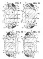
- the plunger 74 is shown in the first position in Figures 5 , 6 , and 9 and the plunger 74 is shown in the second position in Figures 7 and 10 .
- the plunger 74 prevents fluid communication between the cavity 34 and the first aperture 38 when in the first position and the plunger 74 allows fluid communication between the cavity 34 and the first aperture 38 when in the second position.
- the plunger 74 is radially spaced from the first support 48 to define a gap 76 between the plunger 74 and the first support 48.
- the plunger 74 is radially spaced from the first support 48 relative to the longitudinal axis L.
- the plunger 74 is also radially spaced from the first bracket 70 such that the plunger 74 is movable through the first bracket 70 between the first and second positions.
- the plunger 74 is further defined as a first plunger 74 and the gap 76 is further defined as a first gap 76 and will be referred to as the first plunger 74 and the first gap 76 below.
- the solenoid valve assembly 30 can further include a second plunger 78 movably disposed in the second bore 56 of the second support 54 between a third position engaging the housing 32 and a fourth position spaced from the housing 32.
- the second plunger 78 is shown in the third position in Figures 5 and 11 and the second plunger 78 is shown in the fourth position in Figures 8 and 12 .
- the second plunger 78 is radially spaced from the second support 54 to define a second gap 80 between the second plunger 78 and the second support 54.
- the second plunger 78 is radially spaced from the second bracket 72 such that the second plunger 78 is movable through the second bracket 72 between the third and fourth positions.
- the second plunger 78 prevents fluid communication between the cavity 34 and the third aperture 46 when in the third position and the second plunger 78 allows fluid communication between the cavity 34 and the third aperture 46 when in the fourth position.
- first and second plungers 74, 78 are mirror images of each other. It is to further be appreciated that the first and second plungers 74, 78 can be different configurations from each other.
- the first and second plungers 74, 78 can be formed of metal material(s) and more specifically, magnetic material(s). In one embodiment, the metal material(s) of the first and second plungers 74, 78 is further defined as steel. It is to be appreciated that the first and second plungers 74, 78 can be formed of any suitable magnetic material(s).
- the first and second plungers 74, 78 are formed of the magnetic material(s) for moving the first and second plungers 74, 78 in response to the magnetic fields. In other words, when the magnetic field is generated by the first coil 60, the first plunger 74 moves between the first and second positions. Likewise, when the magnetic field is generated by the second coil 62, the second plunger 78 moves between the third and fourth positions.
- the center plate 68 is disposed between the first and second coils 60, 62 for guiding the magnetic field generated by the first coil 60. More specifically, the first and second brackets 70, 72, as well as the center plate 68 and the first and second plates 69, 71 cooperate to guide the magnetic field when the first and/or second coils 60, 62 are in the energized state. Hence, the first bracket 70, the center plate 68, and the first and second plates 69, 71 cooperate to guide or focus the magnetic field through the first gap 76 when the first coil 60 is in the energized state, thus causing the first plunger 74 to move.
- the second bracket 72, the center plate 68, and the first and second plates 69, 71 cooperate to guide or focus the magnetic field through the second gap 80 when the second coil 62 is in the energized state, thus causing the second plunger 78 to move.
- the magnetic field generated by the first and second coils 60, 62 can attract the first and second plungers 74, 78 respectively (paramagnetism).
- the magnetic field generated by the first and second coils 60, 62 can repel the first and second plungers 74, 78 respectively (diamagnetism).
- first and second plungers 74, 78 each define an outer surface 82. More specifically, the outer surface 82 of the first and second plungers 74, 78 each include a shoulder 84 to define a first outer diameter OD 1 and a second outer diameter OD 2 less than the first outer diameter OD 1 , which will be discussed further below.
- the solenoid valve assembly 30 also includes a dampener 86 coupled to one of the first support 48 and the first plunger 74 to prevent direct engagement between the first support 48 and the first plunger 74 as the first plunger 74 moves between the first and second positions during the energized and de-energized states for reducing noise during operation. More specifically, the dampener 86 is coupled to one of the first support 48 and the first plunger 74 adjacent the first gap 76 to prevent direct engagement between the first support 48 and the first plunger 74 as the first plunger 74 moves between the first and second positions during the energized and de-energized states for reducing noise during operation.
- the dampener 86 prevents direct engagement between the first support 48 and the first plunger 74 and maintains the first gap 76 between the first plunger 74 and the first support 48 which allows the first plunger 74 to move more freely. It is to be appreciated that the dampener 86 can be coupled to the first bracket 70.
- the dampener 86 is attached to the first support 48. In one configuration, the dampener 86 is attached to the first support 48 in the first recess 52. The dampener 86 is disposed in the first recess 52 adjacent the first bracket 70. The dampener 86 defines a hole 88 adjacent the first bore 50 with the first plunger 74 disposed in the hole 88. Further, the hole 88 of the dampener 86 is disposed along the longitudinal axis L. The first plunger 74 moves through the hole 88 between the first and second positions.
- the dampener 86 is attached to the first plunger 74.
- the hole 88 is adjacent the first bore 50 with the first plunger 74 and the dampener 86 moving concurrently through the first bore 50.
- the dampener 86 is attached to the outer surface 82 of the first plunger 74, and more specifically, the dampener 86 is attached to the outer surface 82 defining the first outer diameter OD 1 .
- the dampener 86 can be attached to the first support 48, the first plunger 74, or the first bracket 70 by a molding, such as injecting molding, adhesive, press fit, fasteners, welding, or any other suitable method for securing/attaching the dampener 86 thereon.
- the dampener 86 can be defined as an o-ring.
- the dampener 86 is further defined as a first dampener 86 for the below discussion.
- the first dampener 86 includes a lip 90 extending radially toward the first plunger 74 for maintaining the first gap 76 between the first support 48 and the first plunger 74 as the first plunger 74 moves between the first and second positions during the energized and de-energized states. Further, the lip 90 extends radially toward the longitudinal axis L for maintaining the first gap 76 between the first support 48 and the first plunger 74 as the first plunger 74 moves between the first and second positions during the energized and de-energized states.
- the first dampener 86 includes a tab 92 extending outwardly away from the lip 90.
- the tab 92 is utilized for manufacturing of the first dampener 86. If desired, the tab 92 can maintain an orientation or position of the first dampener 86. Further, if desired, the tab 92 can assist in removing the first dampener 86 from the first support 48. It is to be appreciated that the first recess 52 is also complementary to the configuration of the tab 92 of the first recess 52.
- the solenoid valve assembly 30 can further include a second first dampener 94 coupled to one of the second support 54 and the second plunger 78 adjacent the second gap 80 to prevent direct engagement between the second support 54 and the second plunger 78 as the second plunger 78 moves between the third and fourth positions during the energized and de-energized states.
- the second first dampener 94 prevents direct engagement between the second support 54 and the second plunger 78 and maintains the second gap 80 between the second plunger 78 and the second support 54 which allows the second plunger 78 to move more freely.
- the second first dampener 94 can be coupled to the second bracket 72.
- the second first dampener 94 can be attached to the second support 54, the second plunger 78, or the second bracket 72 by a molding, such as injecting molding, adhesive, press fit, fasteners, welding, or any other suitable method for securing/attaching the second first dampener 94 thereon.
- the second first dampener 94 is a mirror image of the first dampener 86, and therefore, also includes the lip 90, the hole 88, and optionally the tab 92 as discussed above and therefore will not be re-discussed.
- the second first dampener 94 can be defined as an o-ring.
- the first dampener 86 and the second first dampener 94 can be different configurations from each other.
- the solenoid valve assembly 30 also includes an armature 96 disposed in the first bore 50.
- the armature 96 is disposed in the second bore 56.
- the armature 96 is coupled to at least one of the first and second supports 48, 54 to prevent movement of the armature 96 in the first and/or second bores 50, 56.
- the armature 96 is coupled to the first support 48 and in another embodiment the armature 96 is coupled to the second support 54. It is to be appreciated that the armature 96 can be coupled to both the first and second supports 48,54.
- the armature 96 can be formed of metal material(s) and more specifically magnetic material(s). In one embodiment, the metal material(s) of the armature 96 is further defined as steel. It is to be appreciated that the armature 96 can be formed of any suitable magnetic material(s). The armature 96 is formed of the magnetic material(s) for guiding the magnetic field generated by the first and/or second coils 60, 62.
- the armature 96 includes a projection 98 for coupling the armature 96 to at least one of the first and second supports 48, 54 for preventing movement of the armature 96 in the first and/or second bores 50, 56.
- the projection 98 extends from the armature 96 away from the longitudinal axis L, and more specifically, the projection 98 extends radially about the armature 96.
- the projection 98 is disposed in one of the first recesses 52 of the first support 48.
- the projection 98 is disposed in the first recess 52 adjacent the center plate 68. It is to be appreciated that the projection 98 can be sandwiched between the first support 48 and the center plate 68.
- the projection 98 is disposed in one of the second recesses 58 of the second support 54.
- the projection 98 is disposed in the second recess 58 adjacent the center plate 68.
- the projection 98 can be sandwiched between the second support 54 and the center plate 68.
- the projection 98 can be defined as a plurality of projections 98 with one of the projections 98 disposed in one of the first recesses 52 and another one of the projections 98 disposed in one of the second recesses 58. It is to further be appreciated that the projection 98 can be in any suitable location.
- the projection 98 provides a stop for the center plate 68 during assembling of the solenoid valve assembly 30.
- the armature 96 can also include an engagement surface adjacent the projection 98 for receiving the center plate 68.
- the center plate 68 is disposed over the engagement surface for securing the center plate 68 to the armature 96.
- the engagement surface can be knurled or any other suitable configuration.
- the armature 96 includes a step 100 facing the first plunger 74.
- the step 100 is further defined as a first step 100 and will be referred to as the first step 100 in the following discussion.
- the armature 96 also includes a second step 102 facing the second plunger 78.
- the first step 100 of the armature 96 faces the shoulder 84 of the first plunger 74 and likewise, the second step 102 of the armature 96 faces the shoulder 84 of the second plunger 78.
- the solenoid valve assembly 30 can further include a biasing member 104 engaging the first plunger 74 and the armature 96 for continuously biasing the first plunger 74 toward the first position. More specifically, the biasing member 104 engages the shoulder 84 of the first plunger 74 and the first step 100 of the armature 96 for continuously biasing the first plunger 74 toward the first position.
- the biasing member 104 is further defined as a first biasing member 104 and further includes a second biasing member 106 engaging the shoulder 84 of the second plunger 78 and the second step 102 of the armature 96 for continuously biasing the second plunger 78 toward the third position. It is to be appreciated that the first and second biasing members 104, 106 can be any suitable configuration and location.
- first and/or second biasing members 104, 106 can be defined as a spring that either pushes or pulls the first and/or second plungers 74, 78 respectively.
- first biasing member 104 can be configured such that the first biasing member 104 continuously bias the first plunger 74 to the second position
- second biasing member 106 can be configured such that the second biasing member 106 continuously bias the second plunger 78 to the fourth position.
- the armature 96 further includes a first distal end 108 and a second distal end 110 spaced from each other along the longitudinal axis L.
- the first step 100 is disposed adjacent the first distal end 108 and the second step 102 is disposed adjacent the second distal end 110.
- the first and second distal ends 108, 110 each include a flat surface 112 and a taper 114.
- the taper 114 of the first distal end 108 slopes upwardly toward the first step 100 and the taper 114 of the second distal end 110 slopes upwardly toward the second step 102.
- first and second distal ends 108, 110 of the armature 96 are mirror images of each other. It is to further be appreciated that the first and second distal ends 108, 110 of the armature 96 can be different configurations from each other.
- the armature 96 also defines a hollow 116 along the longitudinal axis L.
- the hollow 116 is disposed through the armature 96 between the first and second distal ends 108, 110. More specifically, the hollow 116 is disposed through the armature 96 and the flat surface 112 of the first and second distal ends 108, 110. The hollow 116 is spaced from the taper 114 of the first and second distal ends 108, 110. It is to be appreciated that the armature 96 can be any suitable configuration.
- the first and second plungers 74, 78 each include a first end 118 facing the housing 32 and a second end 120 spaced from the first end 118 and facing the armature 96. More specifically, the second end 120 of the first plunger 74 faces the first distal end 108 of the armature 96 and the second end 120 of the second plunger 78 faces the second distal end 110 of the armature 96. Further, the first end 118 of the first plunger 74 faces the first aperture 38 of the first port 36 and the first end 118 of the second plunger 78 faces the third aperture 46 of the third port 44.
- the first and second plungers 74, 78 each include a first flange 122 and a second flange 124 spaced from each other to define a groove 126 between the first and second flanges 122, 124.
- the shoulder 84 of the first plunger 74 is spaced from the first and second flanges 122, 124 of the first plunger 74 with the first outer diameter OD 1 adjacent the second flange 124 of the first plunger 74.
- the shoulder 84 of the second plunger 78 is spaced from the first and second flanges 122, 124 of the second plunger 78 with the first outer diameter OD 1 adjacent the second flange 124 of the second plunger 78.
- the first flange 122 of the first plunger 74 engages the housing 32 when in the first position and the first flange 122 of the second plunger 78 engages the housing 32 when in the third position.
- the first and second flanges 122, 124 of the first plunger 74 are disposed between the housing 32 and the first bracket 70.
- the first and second flanges 122, 124 of the second plunger 78 are disposed between the housing 32 and the second bracket 72.
- the solenoid valve assembly 30 can also include a second dampener 128 spaced from the first dampener 86.
- the second dampener 128 is coupled to one of the first and second ends 118, 120 of the first plunger 74 to prevent direct engagement between the first plunger 74 and one of the housing 32 and the armature 96 for reducing noise during operation.
- the second dampener 128 is coupled to the first end 118 of the first plunger 74 such that the second dampener 128 engages the housing 32 when the first plunger 74 is in the first position. In other words, the second dampener 128 abuts the housing 32 when the first plunger 74 is in the first position.
- the second dampener 128 is sandwiched between the housing 32 and the first flange 122 when the first plunger 74 is in the first position. Therefore, when in the first position, the second dampener 128 is disposed over the first aperture 38 of the first port 36 for preventing fluid from flowing into the cavity 34.
- the second dampener 128 is coupled to the second end 120 of the first plunger 74 such that the second dampener 128 engages the armature 96 when the first plunger 74 is in the second position.
- the second dampener 128 is coupled to the first end 118 of the first plunger 74.
- the second dampener 128 is disposed over the first flange 122 of the first plunger 74. More specifically, the second dampener 128 covers the first flange 122 and is disposed in the groove 126 between the first and second flanges 122, 124 for attaching the second dampener 128 to the first end 118 of the first plunger 74.
- the solenoid valve assembly 30 can further include a second second dampener 130 spaced from the second first dampener 94.
- the second second dampener 130 is coupled to one of the first and second ends 118, 120 of the second plunger 78 to prevent direct engagement between the second plunger 78 and one of the housing 32 and the armature 96 for reducing noise.
- the second second dampener 130 is coupled to the first end 118 of the second plunger 78.
- the second second dampener 130 abuts the housing 32 when the second plunger 78 is in the third position. As such, a portion of the second second dampener 130 is sandwiched between the housing 32 and the first flange 122 when the second plunger 78 is in the third position.
- the second second dampener 130 when in the third position, the second second dampener 130 is disposed over the third aperture 46 of the third port 44 for preventing fluid from flowing out of the cavity 34 and out of the bladder 24.
- the second second dampener 130 is coupled to the first end 118 of the second plunger 78.
- the second second dampener 130 is disposed over the first flange 122 of the second plunger 78. More specifically, the second second dampener 130 covers the first flange 122 and is disposed in the groove 126 between the first and second flanges 122, 124 for attaching the second second dampener 130 to the first end 118 of the second plunger 78.
- the second second dampener 130 is a mirror image of the second dampener 128. It is to further be appreciated that the second dampener 128 and the second second dampener 130 can be different configurations from each other.
- the second end 120 of the first and second plungers 74, 78 each define a depression 132 extending toward the first end 118 respectively.
- the depression 132 of the first plunger 74 is generally complementary to the first distal end 108 of the armature 96 and the depression 132 of the second plunger 78 is generally complementary to the second distal end 110 of the armature 96.
- the depression 132 of the first and second plungers 74, 78 each include an angled portion 134 complementary to the taper 114 of the first and second distal ends 108, 110 of the armature 96 respectively.
- the angled portion 134 of the first and second plungers 74, 78 cooperate with the taper 114 of the first and second distal ends 108, 110 of the armature 96 respectively for increasing an effective stroke of the first and second plungers 74, 78.
- the angled portion 134 of the first and second plungers 74, 78 overlap the taper 114 of the first and second distal ends 108, 110 of the armature 96, respectively. Therefore, a distance between the first plunger 74 and the armature 96 along the longitudinal axis L is decreased thus increasing the effective stroke of the first plunger 74 when the first coil 60 is in the energized state.
- the depression 132 of the first and second plungers 74, 78 each include a cradle 136 adjacent the angled portion 134 with a portion of the cradle 136 complementary to the flat surface 112 of the first and second distal ends 108, 110 of the armature 96 respectively.
- first and second plungers 74, 78 each define a chamber 138 facing the hollow 116 of the armature 96. More specifically, the chamber 138 of the first plunger 74 extends from the second end 120 toward the first end 118 of the first plunger 74. Likewise, the chamber 138 of the second plunger 78 extends from the second end 120 toward the first end 118 of the second plunger 78. It is to be appreciated that the first and second plungers 74, 78 can be any suitable configuration.
- the solenoid valve assembly 30 can further include a guide 140 attached to the first plunger 74 such that the guide 140 moves concurrently with the first plunger 74 between the first and second positions.
- the guide 140 is further defined as a first guide 140 and will be referred to as the first guide 140 in the below discussion.
- the solenoid valve assembly 30 further includes a second guide 142 attached to the second plunger 78 such that the second guide 142 moves concurrently with the second plunger 78 between the third and fourth positions.
- the chamber 138 of the first plunger 74 and the hollow 116 of the armature 96 receive the first guide 140.
- the chamber 138 of the second plunger 78 and the hollow 116 of the armature 96 receive the second guide 142.
- the first guide 140 can be press fit to the chamber 138 of the first plunger 74 and the second guide 142 can be press fit to the chamber 138 of the second plunger 78. It is to be appreciated that the first and second guides 140, 142 can be attached to the first and second plungers 74, 78 respectively by any suitable method, such as for example, adhesive, welding, fasteners, friction/press fit, etc.
- the first guide 140 generally guides the first plunger 74 along the longitudinal axis L during movement between the first and second positions.
- the second guide 142 generally guides 140 the second plunger 78 along the longitudinal axis L during movement between the third and fourth positions.
- the first and second guides 140, 142 each define a length. Increasing the length of the first and second guides 140, 142 provide better guiding of the first and second plungers 74, 78.
- the hollow 116 of the armature 96 is configured to guide the first and second guides 140, 142 during movement of the first and second plungers 74, 78 respectively.
- the hollow 116 of the armature 96 defines a first inner diameter ID 1 a second inner diameter ID 2 adjacent the first inner diameter ID 1 , and a third inner diameter ID 3 with the second inner diameter ID 2 disposed between the first and third inner diameters ID 1 , ID 3 .
- the second and third inner diameters ID 2 , ID 3 are greater than the first inner diameter ID 1 .
- the second inner diameter ID 2 is less than the third inner diameter ID 3 with the first guide 140 configured to be movable in the second and third inner diameters ID 2 , ID 3 . As such, the first guide 140 cannot enter the first inner diameter ID 1 .
- the hollow 116 of the armature 96 also defines a fourth inner diameter ID 4 adjacent the first inner diameter ID 1 and spaced from the second and third inner diameters ID 2 , ID 3 .
- the hollow 116 of the armature 96 defines a fifth inner diameter ID 5 with the fourth inner diameter ID 4 disposed between the first and fifth inner diameters ID 1 , ID 5 .
- the fourth and fifth inner diameters ID 4 , ID 5 are greater than the first inner diameter ID 1 .
- the fourth inner diameter ID 4 is less than the fifth inner diameter ID 5 with the second guide 142 configured to be movable in the fourth and fifth inner diameters ID 4 , ID 5 . As such, the second guide 142 cannot enter the first inner diameter ID 1 .
- the third inner diameter ID 3 provides less guidance to the first guide 140 than the second inner diameter ID 2 because of the third inner diameter ID 3 is greater than the second inner diameter ID 2 .
- the second inner diameter ID 2 provides the most guidance because the second inner diameter ID 2 is closer to an outer diameter of the first guide 140.
- the fifth diameter ID 5 provides less guidance to the second guide 142 than the fourth inner diameter ID 4 because of the fifth inner diameter ID 5 is greater than the fourth inner diameter ID 4 .
- the fourth inner diameter ID 4 provides the most guidance because the fourth inner diameter ID 4 is closer to an outer diameter of the second guide 142.
- the third and fifth inner diameters ID 3 , ID 5 allow the first and second guides 140, 142 respectively to move transverse to the longitudinal axis L.
- the second and fourth inner diameters ID 2 , ID 4 allow the first and second guides 140, 142 respectively to move transverse to the longitudinal axis L.
- the first and second guides 140, 142 are spaced from a portion of the hollow 116 to allow the first and second guides 140, 142 to move off-center from the longitudinal axis L.
- the first and second guides 140, 142 can further be defined as elongated pins.
- first and second guides 140, 142 can be any suitable configuration for guiding the first and second plungers 74, 78 respectively.
- first and second guides 140, 142 can be attached to the armature 96 such that the first plunger 74 moves relative to the first guide 140 and the second plunger 78 moves relative to the second guide 142.
- the first and second guides 140, 142 are each formed of metal material(s) and more specifically non-magnetic material(s)., In one embodiment, the metal material(s) of the first and second guides 140, 142 is further defined as brass. It is to be appreciated that the first and second guides 140, 142 can be formed of any suitable non-magnetic material(s).
- the solenoid valve assembly 30 can further include a third dampener 144 coupled to the second end 120 of the first plunger 74.
- the second dampener 128 prevents direct engagement between the first plunger 74 and the housing 32 and the third dampener 144 prevents direct engagement between the first plunger 74 and the armature 96.
- the third dampener 144 is disposed in the cradle 136 of the depression 132 of the second end 120 of the first plunger 74. When the first plunger 74 moves to the second position, the third dampener 144 is sandwiched between the second end 120 of the first plunger 74 and the first distal end 108 of the armature 96.
- the third dampener 144 is sandwiched between the cradle 136 of the depression 132 of the first plunger 74 and the flat surface 112 of the first distal end 108 of the armature 96.
- the third dampener 144 is attached to the first guide 140. It is to be appreciated that the third dampener 144 can be attached to the armature 96.
- the solenoid valve assembly 30 can further include a second third dampener 146 coupled to the second end 120 of the second plunger 78.
- the second second dampener 130 prevents direct engagement between the second plunger 78 and the housing 32 and the second third dampener 146 prevents direct engagement between the second plunger 78 and the armature 96.
- the second third dampener 146 is disposed in the cradle 136 of the depression 132 of the second end 120 of the second plunger 78. When the second plunger 78 moves to the fourth position, the second third dampener 146 is sandwiched between the second end 120 of the second plunger 78 and the second distal end 110 of the armature 96.
- the second third dampener 146 is sandwiched between the cradle 136 of the depression 132 of the second plunger 78 and the flat surface 112 of the second distal end 110 of the armature 96.
- the second third dampener 146 is attached to the second guide 142. It is to be appreciated that the second third dampener 146 can be attached to the armature 96. It is to be appreciated that the second third dampener 146 is a mirror image of the third dampener 144. It is to further be appreciated that the third dampener 144 and the second third dampener 146 can be different configurations from each other.
- All of the dampeners 86, 94, 128, 130, 144, 146 can be formed of polymeric material(s) and more specifically plastic material(s).
- the plastic material(s) of the dampeners 86, 94, 128, 130, 144, 146 can be thermoplastic material(s) and/or themoset material(s).
- the polymeric material(s) of the dampeners 86, 94, 128, 130, 144, 146 is further defined as silicon.
- the polymeric material(s) of the dampeners 86, 94, 128, 130, 144, 146 is further defined as thermoplastic elastomers (TPE).
- one or more of the dampeners 86, 94, 128, 130, 144, 146 can be formed of silicon and one or more the dampeners 86, 94, 128, 130, 144, 146 can be formed of TPE. It is to further be appreciated that the dampeners 86, 94, 128, 130, 144, 146 can be formed of any suitable material(s).
- the solenoid valve assembly 30 can be further defined a plurality of solenoid valve assemblies 30.
- the solenoid valve assemblies 30 can be coupled to each other in a row with each solenoid valve assembly 30 controlling one bladder 24.
- the housing 32 of each solenoid valve assembly 30 defines a path 148 adjacent the first aperture 38 of the first port 36, and more specifically, the path 148 is in fluid communication with the first aperture 38.
- the path 148 of each of the solenoid valve assemblies 30 cooperate with each other for guiding the fluid from one solenoid valve assembly 30 to the next for selectively inflating the desired bladder(s) 24.
- the solenoid valve assemblies 30 can be grouped together in various locations.
- the operation of the seat assembly 20 is discussed below.
- the pump 26 is turned on to flow fluid down the path 148 of the solenoid valve assemblies 30.
- the function of one solenoid valve assembly 30 will be discussed in relation to inflating and deflating one bladder 24.
- the first plunger 74 is disposed in the first position and the second plunger 78 is disposed in the third position such that no fluid flows into or out of the cavity 34 of the housing 32.
- the second dampener 128 engages the housing 32 over the first aperture 38 for preventing fluid from flowing into the cavity 34 and the second second dampener 130 engages the housing 32 over the third aperture 46 for preventing fluid from flowing out of the cavity 34 and out of the bladder 24.
- the second plunger 78 remains in the third position.
- the user engages a first switch (not shown) and current flows through one pair of the wires 66 to the first coil 60 such that the first coil 60 is energized to the energized state, thus generating the magnetic field.
- the first bracket 70, the center plate 68, and the first and second plates 69, 71 cooperate to guide the magnetic field through the first gap 76 when the first coil 60 is in the energized state, thus causing the first plunger 74 to move.
- the first plunger 74 moves away from the housing 32 to the second position in response to the magnetic field being generated.
- the magnetic field is strong enough to overcome a biasing force of the first biasing member 104 to move the first plunger 74 to the second position.
- the first plunger 74 moves off-center from the longitudinal axis L as shown in Figures 7 and 10 .
- the magnetic field pulls the first plunger 74 transverse to the longitudinal axis L.
- This off-center movement causes the first plunger 74 to engage or compress a portion of the first dampener 86 thus preventing direct contact between the first plunger 74 and the first support 48 and reducing noise during operation of the first plunger 74.
- the first plunger 74 engages the lip 90 of the first dampener 86.
- the first plunger 74 can engage the first dampener 86 in any transverse direction to the longitudinal axis L.
- the magnetic field can cause the first plunger 74 to move off-center relative to the longitudinal axis L in any direction. It is to be appreciated that the off-center movement can be so small that the first plunger 74 does not engage the first dampener 86.
- the third dampener 144 is sandwiched or compressed between the second end 120 of the first plunger 74 and the first distal end 108 of the armature 96 for preventing direct contact between the first plunger 74 and the armature 96 for reducing noise during operation of the first plunger 74.
- the bladder 24 is inflated to a desired amount, the user disengages the first switch and current stops flowing through the pair of the wires 66 to the first coil 60 such that the first coil 60 is in the de-energized state and no magnetic field is generated.
- the first biasing member 104 biases the first plunger 74 back to the first position such that the second dampener 128 engages the housing 32 over the first aperture 38 for preventing fluid from flowing into the cavity 34.
- the second dampener 128 is sandwiched or compressed between the housing 32 and the first flange 122 of the first plunger 74 and the third dampener 144 is de-compressed.
- the first plunger 74 remains in the first position.
- the user engages a second switch (not shown) and current flows through another pair of the wires 66 to the second coil 62 such that the second coil 62 is energized to the energized state, thus generating the magnetic field.
- the second bracket 72, the center plate 68, and the first and second plates 69, 71 cooperate to guide the magnetic field through the second gap 80 when the second coil 62 is in the energized state, thus causing the second plunger 78 to move.
- the second plunger 78 moves away from the housing 32 to the fourth position in response to the magnetic field being generated.
- the magnetic field is strong enough to overcome a biasing force of the second biasing member 106 to move the second plunger 78 to the fourth position.
- the second plunger 78 moves off-center from the longitudinal axis L as shown in Figures 8 and 12 .
- the magnetic field pulls the second plunger 78 transverse to the longitudinal axis L.
- This off-center movement causes the second plunger 78 to engage or compress a portion of the second first dampener 94 thus preventing direct contact between the second plunger 78 and the second support 54 and reducing noise during operation of the second plunger 78.
- the second first dampener 94 engages the lip 90 of the second first dampener 94.
- the second plunger 78 can engage the second first dampener 94 in any transverse direction to the longitudinal axis L.
- the magnetic field can cause the second plunger 78 to move off-center relative to the longitudinal axis L in any direction. It is to be appreciated that the off-center movement can be so small that the second plunger 78 does not engage the second first dampener 94.
- the second third dampener 146 is sandwiched or compressed between the second end 120 of the second plunger 78 and the second distal end 110 of the armature 96 for preventing direct contact between the second plunger 78 and the armature 96 for reducing noise during operation of the second plunger 78.
- the bladder 24 is deflated to a desired amount, the user disengages the second switch and current stops flowing through the pair of the wires 66 to the second coil 62 such that the second coil 62 is in the de-energized state and no magnetic field is generated.
- the second biasing member 106 biases the second plunger 78 back to the third position such that the second second dampener 130 engages the housing 32 over the third aperture 46 for preventing fluid from flowing out of the cavity 34 and out of the bladder 24.
- the second second dampener 130 is sandwiched or compressed between the housing 32 and the first flange 122 of the second plunger 78 and the second third dampener 146 is de-compressed.
- first and second plungers 74, 78 and the first and second guides 140, 142 moving off-center from the longitudinal axis L in Figures 7 , 8 , 10, and 12 are exaggerated for illustrative purposes only.
Landscapes
- Engineering & Computer Science (AREA)
- General Engineering & Computer Science (AREA)
- Physics & Mathematics (AREA)
- Electromagnetism (AREA)
- Mechanical Engineering (AREA)
- Power Engineering (AREA)
- Aviation & Aerospace Engineering (AREA)
- Transportation (AREA)
- Magnetically Actuated Valves (AREA)
Claims (23)
- Solenoidventilaufbau (30) mit
einem Gehäuse (32), das einen Hohlraum (34) definiert, einem Träger (48), der in dem Hohlraum (34) angeordnet ist und eine Bohrung (50) entlang einer Längsachse definiert,
einer Spule (60), die um den Träger (48) herum angeordnet ist und die einen mit Energie versorgten Zustand zum Erzeugen eines Magnetfeldes und einen nicht mit Energie versorgten Zustand definiert,
einem Kolben (74), der in der Bohrung (50) des Trägers (48) zwischen einer ersten Position in Berührung mit dem Gehäuse (32) und einer zweiten Position auf Abstand zu dem Gehäuse (32) beweglich ist, wobei der Kolben (74) radial auf Abstand zu dem Träger (48) relativ zu der Längsachse liegt, um eine Lücke (76) zwischen dem Kolben (74) und dem Träger (48) zu definieren, und
einem Dämpfer (86), der angrenzend an die Lücke (76) mit einem von dem Träger (48) und dem Kolben (74) gekoppelt ist, wobei der Dämpfer (86) sich in die Lücke (76) erstreckt, um einen Zwischenraum zwischen dem Dämpfer (86) und dem anderen von dem Kolben (74) und dem Träger (48) in der ersten Position zu definieren, wobei der Dämpfer (86) die Lücke (76) wenigstens teilweise aufrechterhält, um eine direkte Berührung zwischen dem Träger (48) und dem Kolben (74) zu verhindern, wenn der Kolben (74) sich zwischen den ersten und zweiten Positionen während der mit Energie versorgten und nicht mit Energie versorgten Zustände bewegt, um Geräusche während des Betriebs zu reduzieren. - Solenoidventilaufbau (30) nach Anspruch 1, wobei der Dämpfer (86) eine Lippe (90) aufweist, die radial zu der Längsachse hin verläuft, um den Zwischenraum weiter zu definieren und die Lücke (76) zwischen dem Träger (48) und dem Kolben (74) aufrechtzuerhalten, wenn der Kolben (74) sich während der mit Energie versorgten und nicht mit Energie versorgten Zustände zwischen den ersten und zweiten Positionen bewegt.
- Solenoidventilaufbau (30) nach Anspruch 2, wobei der Dämpfer (86) einen Fortsatz (92) aufweist, der sich nach außen weg von der Lippe (90) erstreckt.
- Solenoidventilaufbau (30) nach Anspruch 1, wobei der Dämpfer (86) an dem Träger (48) angebracht ist und eine Öffnung (88) entlang der Längsachse definiert, wobei der Kolben (74) in der Öffnung (88) angeordnet ist.
- Solenoidventilaufbau (30) nach Anspruch 4, wobei der Träger (48) eine Vertiefung (52) definiert, wobei der Dämpfer (86) in der Vertiefung (52) mit dem Träger (48) verbunden ist.
- Solenoidventilaufbau (30) nach Anspruch 1, wobei der Dämpfer (86) eine Öffnung (88) entlang der Längsachse definiert, wobei der Kolben (74) in der Öffnung (88) angeordnet ist, so dass der Dämpfer (86) mit dem Kolben (74) verbunden ist.
- Solenoidventilaufbau (30) nach Anspruch 6, wobei der Kolben (74) eine äußere Oberfläche (82) definiert, wobei der Dämpfer (86) mit der äußeren Oberfläche (82) verbunden ist.
- Solenoidventilaufbau (30) nach Anspruch 7, wobei die äußere Oberfläche (82) des Kolbens (74) eine Schulter (84) umfasst, um einen ersten äußeren Durchmesser und einen zweiten äußeren Durchmesser zu definieren, der kleiner als der erste äußere Durchmesser ist, wobei der Dämpfer (86) an der äußeren Oberfläche (82), die den ersten äußeren Durchmesser definiert, angebracht ist.
- Solenoidventilaufbau (30) nach einem der vorhergehenden Ansprüche, der weiter aufweist:einen Anker (96), der in der Bohrung (50) angeordnet ist und mit dem Träger (48) verbunden ist, um Bewegung des Ankers (96) in der Bohrung (50) zu verhindern,wobei der Kolben (74) ein erstes, dem Gehäuse (32) zugewandtes Ende (118) und ein zweites Ende hat, das auf Abstand zu dem ersten Ende (118) liegt und dem Anker (96) zugewandt ist, undeinen zweiten Dämpfer (128), der auf Abstand zu dem ersten Dämpfer (86) liegt und mit einem von dem ersten Ende (118) und dem zweiten Ende (120) des Kolbens (74) verbunden ist, um direkte Berührung zwischen dem Kolben (74) und einem von dem Gehäuse (32) und dem Anker (96) zu verhindern, um Geräusche während des Betriebs zu reduzieren.
- Solenoidventilaufbau (30) nach Anspruch 9, wobei der Anker (96) eine der Schulter (84) des Kolbens (74) zugewandte Stufe (100) aufweist und weiter ein Vorspannglied (104) vorhanden ist, das an der Schulter (84) und der Stufe (100) ansetzt, um den Kolben (74) kontinuierlich zu der ersten Position hin vorzuspannen.
- Solenoidventilaufbau (30) nach Anspruch 9, wobei der zweite Dämpfer (128) mit dem ersten Ende (118) des Kolbens (74) verbunden ist und weiter ein dritter Dämpfer (144) vorhanden ist, der mit dem zweiten Ende (120) des Kolbens (74) verbunden ist, so dass der zweite Dämpfer (128) direkten Kontakt zwischen dem Kolben (74) und dem Gehäuse (32) und der dritte Dämpfer (144) direkten Kontakt zwischen dem Kolben (74) und dem Anker (96) verhindert.
- Solenoidventilaufbau (30) nach Anspruch 11, der weiter eine an dem Kolben (74) angebrachte Führung (140) aufweist, so dass die Führung (140) sich mit dem Kolben (74) zwischen den ersten und zweiten Positionen bewegt, wobei der dritte Dämpfer (144) an der Führung (140) befestigt ist.
- Solenoidventilaufbau (30) nach Anspruch 12, wobei der Kolben (74) eine Kammer definiert und der Anker (96) eine Aushöhlung (116) definiert, wobei die Kammer und die Aushöhlung (116) die Führung (140) aufnehmen.
- Solenoidventilaufbau (30) nach Anspruch 9, wobei der zweite Dämpfer (128) mit dem ersten Ende (118) des Kolbens (74) verbunden ist, so dass der zweite Dämpfer (128) das Gehäuse (32) berührt, wenn der Kolben (74) sich in der ersten Position befindet.
- Solenoidventilaufbau (30) nach Anspruch 9, wobei der zweite Dämpfer (128) mit dem zweiten Ende (120) des Kolbens (74) verbunden ist, so dass der zweite Dämpfer (128) den Anker (96) berührt, wenn sich der Kolben (74) in der zweiten Position befindet.
- Solenoidventilaufbau (30) nach Anspruch 9, der weiter ein Vorspannglied (104) aufweist, das sich an dem Kolben (74) und dem Anker (96) abstützt, um den Kolben (74) kontinuierlich zu der ersten Position hin vorzuspannen.
- Sitzaufbau (20) für ein Fahrzeug mit einem Solenoidventilaufbau (30) nach einem der vorhergehenden Ansprüche, wobei der Sitzaufbau (20) aufweist:einen Sitzrahmen (22), der mit dem Solenoidventilaufbau (30) verbunden ist, undein Blasenelement (74), das mit dem Sitzrahmen (22) und mit dem Solenoidventilaufbau (30) verbunden ist und einen aufgeblasenen Zustand mit einem aufgeblasenen Blasenelement (24) und einen entlüfteten Zustand mit entlüftetem Blasenelement (24) definiert.
- Sitzaufbau (20) nach Anspruch 17, wobei das Gehäuse (32) einen ersten Anschluss (36) aufweist, der eine erste Öffnung (38) angrenzend an den Hohlraum (34) definiert, wobei der Kolben (74) Fluidkommunikation zwischen dem Hohlraum (34) und der ersten Öffnung (38) verhindert, wenn er sich in der ersten Position befindet, und wobei der Kolben (74) Fluidkommunikation zwischen dem Hohlraum (34) und der ersten Öffnung (38) zulässt, wenn er sich in der zweiten Position befindet.
- Sitzaufbau (20) nach Anspruch 18, wobei das Gehäuse (32) einen zweiten Anschluss (40) angrenzend an den Hohlraum (34) und auf Abstand zu dem ersten Anschluss (36) aufweist, wobei das Blasenelement (24) mit dem zweiten Anschluss (40) verbunden ist und wobei der zweite Anschluss (40) eine zweite Öffnung (42) in Fluidkommunikation mit dem Hohlraum (34) und mit dem Blasenelement (24) definiert, um das Blasenelement (24) in den aufgeblasenen Zustand aufzublasen und das Blasenelement (24) in den entlüfteten Zustand zu entlüften.
- Sitzaufbau (20) nach Anspruch 17, wobei der Kolben (74) weiter als ein erster Kolben (74) definiert ist, die Lücke (76) weiter als eine erste Lücke (76) definiert ist, der Träger (48) weiter als ein erster Träger (48) und die Bohrung (50) weiter als eine erste Bohrung (50) definiert ist und wobei ein zweiter Träger (54) vorhanden ist, der benachbart zu dem ersten Träger (48) liegt und eine zweite Bohrung (56) benachbart zu der ersten Bohrung (50) definiert, und wobei weiter ein zweiter Kolben (78) vorhanden ist, der in der zweiten Bohrung (56) des zweiten Trägers (54) beweglich zwischen einer dritten Position in Anlage an dem Gehäuse (32) und einer vierten Position auf Abstand zu dem Gehäuse (32) angeordnet ist, wobei der zweite Kolben (78) radial auf Abstand zu dem zweiten Träger (54) liegt, um eine zweite Lücke (80) zwischen dem zweiten Kolben (78) und dem zweiten Träger (54) zu definieren.
- Sitzaufbau (20) nach Anspruch 20, wobei die Spule (60) weiter als eine erste Spule (60) definiert ist und der Dämpfer (86) weiter als ein erster Dämpfer (86) definiert ist und weiter eine zweite Spule (62) vorhanden ist, die um den zweiten Träger (54) angeordnet ist und die einen mit Energie versorgtem Zustand zum Erzeugen eines Magnetfeldes und einen nicht mit Energie versorgten Zustand definiert, und weiter ein zweiter Dämpfer (94) vorhanden ist, der mit einem von dem zweiten Träger (54) und den zweiten Kolben (78) angrenzend an die zweite Lücke (80) verbunden ist, um direkten Kontakt zwischen dem zweiten Träger (54) und dem zweiten Kolben (78) zu verhindern, wenn sich der zweite Kolben (78) zwischen den dritten und vierten Positionen während der mit Energie versorgten und der nicht mit Energie versorgten Zustände bewegt.
- Sitzaufbau (20) nach Anspruch 20, wobei das Gehäuse (32) einen dritten Anschluss aufweist, der eine dritte Öffnung (46) angrenzend an den Hohlraum (34) definiert, wobei der zweite Kolben (78) Fluidkommunikation zwischen dem Hohlraum (34) und der dritten Öffnung (46) verhindert, wenn er sich in der dritten Position befindet, und der zweite Kolben (78) Fluidkommunikation zwischen dem Hohlraum (34) und der dritten Öffnung (46) zulässt, wenn er sich in der vierten Position befindet.
- Sitzaufbau (20) nach Anspruch 17, wobei der Dämpfer (86) eine Lippe (90) aufweist, die radial zu dem Kolben hin (74) verläuft, um die Lücke zwischen dem Träger (48) und dem Kolben (74) aufrechtzuerhalten, wenn der Kolben (74) sich zwischen den ersten und zweiten Positionen während der mit Energie versorgten und der nicht mit Energie versorgten Zustände bewegt.
Applications Claiming Priority (1)
| Application Number | Priority Date | Filing Date | Title |
|---|---|---|---|
| PCT/IB2011/001702 WO2013011340A1 (en) | 2011-07-20 | 2011-07-20 | Solenoid valve assembly for a seat of a vehicle |
Publications (2)
| Publication Number | Publication Date |
|---|---|
| EP2734762A1 EP2734762A1 (de) | 2014-05-28 |
| EP2734762B1 true EP2734762B1 (de) | 2015-04-29 |
Family
ID=44651870
Family Applications (1)
| Application Number | Title | Priority Date | Filing Date |
|---|---|---|---|
| EP11757409.5A Active EP2734762B1 (de) | 2011-07-20 | 2011-07-20 | Elektromagnetische ventilmontage für fahrzeugsitz |
Country Status (4)
| Country | Link |
|---|---|
| US (1) | US9677683B2 (de) |
| EP (1) | EP2734762B1 (de) |
| CN (1) | CN103688093B (de) |
| WO (1) | WO2013011340A1 (de) |
Families Citing this family (21)
| Publication number | Priority date | Publication date | Assignee | Title |
|---|---|---|---|---|
| DE102014221796A1 (de) * | 2014-10-27 | 2016-04-28 | Conti Temic Microelectronic Gmbh | Ventileinheit zur Steuerung des Durchflusses eines Druckmittels sowie Ventilanordnung |
| DE102015213221A1 (de) * | 2015-07-15 | 2017-01-19 | Robert Bosch Gmbh | Ventil zum Zumessen eines Fluids |
| CN105570522B (zh) * | 2015-08-14 | 2018-01-02 | 北京光华荣昌汽车部件有限公司 | 气悬浮座椅升降用磁力控制气阀 |
| DE102015219195B4 (de) | 2015-10-05 | 2019-07-04 | Conti Temic Microelectronic Gmbh | Pneumatisches Magnetventil |
| DE102015219176B3 (de) | 2015-10-05 | 2017-03-30 | Conti Temic Microelectronic Gmbh | Pneumatisches Magnetventil |
| DE102015219207B3 (de) * | 2015-10-05 | 2017-02-09 | Conti Temic Microelectronic Gmbh | Druckverteiler für ein Kraftfahrzeug |
| DE102015219182B4 (de) | 2015-10-05 | 2019-07-04 | Conti Temic Microelectronic Gmbh | Pneumatisches Magnetventil |
| DE102015219197B4 (de) | 2015-10-05 | 2019-07-04 | Conti Temic Microelectronic Gmbh | Pneumatisches Magnetventil |
| KR101784149B1 (ko) * | 2015-10-08 | 2017-11-07 | 현대다이모스(주) | 차량용 공압 밸브 |
| KR20170059047A (ko) * | 2015-11-19 | 2017-05-30 | 현대다이모스(주) | 차량용 공압 밸브 |
| US10993546B2 (en) | 2016-10-28 | 2021-05-04 | Sleep Number Corporation | Noise reducing plunger |
| DE102018206549B4 (de) | 2018-04-27 | 2020-02-20 | Conti Temic Microelectronic Gmbh | Pneumatisches Magnetventil |
| US10825595B2 (en) * | 2018-07-06 | 2020-11-03 | Hamilton Sundstrand Corporation | Solenoid dampening during non-active operation |
| EP3699466B1 (de) * | 2019-02-19 | 2022-07-13 | Schukra Gerätebau GmbH | Fluidventilsystem mit modulen und verfahren zur herstellung davon |
| DE202019101901U1 (de) * | 2019-04-02 | 2020-04-03 | Alfmeier Präzision SE | Hubelement und Verstelleinrichtung |
| EP3990813A4 (de) | 2019-06-28 | 2023-08-02 | Leggett & Platt Canada Co. | Fluidverwaltungssystem |
| WO2021026630A1 (en) * | 2019-08-09 | 2021-02-18 | Leggett & Platt Canada Co. | Latching valve |
| EP3869074B1 (de) | 2020-02-24 | 2023-06-21 | Schukra Berndorf GmbH | Elektrisch betätigte ventile |
| US11832728B2 (en) | 2021-08-24 | 2023-12-05 | Sleep Number Corporation | Controlling vibration transmission within inflation assemblies |
| KR102667651B1 (ko) * | 2022-10-27 | 2024-05-30 | 주식회사 디에스시동탄 | 솔레노이드 밸브 |
| WO2025188939A1 (en) * | 2024-03-06 | 2025-09-12 | Gentherm Incorporated | Suspension plate assembly for pneumatics |
Family Cites Families (19)
| Publication number | Priority date | Publication date | Assignee | Title |
|---|---|---|---|---|
| US3446473A (en) * | 1964-11-23 | 1969-05-27 | Monsanto Co | Pulsed solenoid control valves |
| US4072919A (en) | 1976-11-03 | 1978-02-07 | Addmaster Corporation | Solenoid construction |
| US4611632A (en) * | 1985-05-06 | 1986-09-16 | Imperial Clevite Inc. | Hydraulic solenoid valve structure |
| US5300908A (en) | 1990-10-10 | 1994-04-05 | Brady Usa, Inc. | High speed solenoid |
| US5150879A (en) * | 1991-05-08 | 1992-09-29 | Valve Tech, Inc. | Thruster valve |
| US5663700A (en) | 1995-08-25 | 1997-09-02 | Trombetta Corporation | Sound dampening solenoid |
| FR2761447A1 (fr) | 1997-03-26 | 1998-10-02 | Eaton Sa Monaco | Electrovanne cyclee de regulation de debit de fluide |
| US6105616A (en) * | 1997-03-28 | 2000-08-22 | Sturman Industries, Inc. | Double actuator control valve that has a neutral position |
| DE19805049A1 (de) | 1998-02-09 | 1999-08-12 | Schultz Wolfgang E | Elektromagnet |
| US5967608A (en) | 1998-05-06 | 1999-10-19 | Bytec Incorporated | Pneumatic lumbar adjustment system |
| CN2349062Y (zh) * | 1998-08-06 | 1999-11-17 | 毛征 | 气垫车座 |
| DE19905176A1 (de) | 1999-02-09 | 2000-08-10 | Fev Motorentech Gmbh | Elektromagnetischer Aktuator mit Luftdämpfungselement |
| US6595485B2 (en) | 2001-08-08 | 2003-07-22 | Delphi Technologies, Inc. | Solenoid valve with cushion between plunger and plunger stop |
| US6935612B2 (en) | 2003-05-21 | 2005-08-30 | Airsep Corporation | Solenoid valve |
| DE10343940A1 (de) * | 2003-09-23 | 2005-04-14 | Robert Bosch Gmbh | Magnetventil mit geräuschreduzierender Dämpferscheibe |
| KR20060006405A (ko) | 2004-07-16 | 2006-01-19 | 현대자동차주식회사 | 솔레노이드 |
| EP1991768A1 (de) * | 2006-02-02 | 2008-11-19 | Borgwarner, Inc. | Turbolader |
| DE102007012151B4 (de) | 2007-03-12 | 2009-09-10 | Thomas Magnete Gmbh | Proportionalmagnet |
| FR2921992B1 (fr) | 2007-10-04 | 2009-12-11 | Cartier Technologies G | Vanne a clapet a pression equilibree. |
-
2011
- 2011-07-20 EP EP11757409.5A patent/EP2734762B1/de active Active
- 2011-07-20 WO PCT/IB2011/001702 patent/WO2013011340A1/en not_active Ceased
- 2011-07-20 CN CN201180072321.7A patent/CN103688093B/zh active Active
- 2011-07-20 US US14/233,656 patent/US9677683B2/en active Active
Also Published As
| Publication number | Publication date |
|---|---|
| US20140191549A1 (en) | 2014-07-10 |
| US9677683B2 (en) | 2017-06-13 |
| CN103688093A (zh) | 2014-03-26 |
| WO2013011340A1 (en) | 2013-01-24 |
| CN103688093B (zh) | 2016-08-10 |
| EP2734762A1 (de) | 2014-05-28 |
Similar Documents
| Publication | Publication Date | Title |
|---|---|---|
| EP2734762B1 (de) | Elektromagnetische ventilmontage für fahrzeugsitz | |
| US6598852B2 (en) | Solenoid valve | |
| US6985060B2 (en) | Control unit for vehicle brake system | |
| US8368493B2 (en) | Linear solenoid | |
| JP4058749B2 (ja) | 電磁駆動装置およびそれを用いた電磁弁 | |
| US6405757B1 (en) | Low power solenoid valve assembly | |
| KR101900587B1 (ko) | 폴 피스와 플럭스 슬리브의 정렬불량에 강한 솔레노이드 | |
| KR20150098209A (ko) | 전자 밸브 | |
| JP2010278403A (ja) | リニアアクチュエータ | |
| EP2221516A1 (de) | Elektromagnetisches ventil | |
| KR20210064375A (ko) | 솔레노이드 | |
| US20150108382A1 (en) | Solenoid valve | |
| KR20180109711A (ko) | 전자기 밸브 및 전자기 밸브의 제조 방법 | |
| KR20190065313A (ko) | 전자기 액추에이터 | |
| JP2018162867A5 (de) | ||
| US7513482B2 (en) | Actuator for controlling brake hydraulic pressure and solenoid valve thereof | |
| JP2016017572A (ja) | ソレノイドバルブ | |
| JP2008196597A (ja) | リニアソレノイド | |
| US20170114764A1 (en) | Fuel injection valve | |
| US7073770B2 (en) | Electromagnetic valve | |
| US11948737B2 (en) | Solenoid | |
| JP7650608B2 (ja) | ソレノイドバルブ | |
| US11908620B2 (en) | Solenoid | |
| US11948738B2 (en) | Systems and methods for a solenoid having a permanent magnet | |
| JP2007100841A (ja) | スプール弁装置 |
Legal Events
| Date | Code | Title | Description |
|---|---|---|---|
| PUAI | Public reference made under article 153(3) epc to a published international application that has entered the european phase |
Free format text: ORIGINAL CODE: 0009012 |
|
| 17P | Request for examination filed |
Effective date: 20131212 |
|
| AK | Designated contracting states |
Kind code of ref document: A1 Designated state(s): AL AT BE BG CH CY CZ DE DK EE ES FI FR GB GR HR HU IE IS IT LI LT LU LV MC MK MT NL NO PL PT RO RS SE SI SK SM TR |
|
| DAX | Request for extension of the european patent (deleted) | ||
| GRAP | Despatch of communication of intention to grant a patent |
Free format text: ORIGINAL CODE: EPIDOSNIGR1 |
|
| INTG | Intention to grant announced |
Effective date: 20150127 |
|
| GRAS | Grant fee paid |
Free format text: ORIGINAL CODE: EPIDOSNIGR3 |
|
| GRAA | (expected) grant |
Free format text: ORIGINAL CODE: 0009210 |
|
| AK | Designated contracting states |
Kind code of ref document: B1 Designated state(s): AL AT BE BG CH CY CZ DE DK EE ES FI FR GB GR HR HU IE IS IT LI LT LU LV MC MK MT NL NO PL PT RO RS SE SI SK SM TR |
|
| REG | Reference to a national code |
Ref country code: GB Ref legal event code: FG4D |
|
| REG | Reference to a national code |
Ref country code: CH Ref legal event code: EP |
|
| REG | Reference to a national code |
Ref country code: AT Ref legal event code: REF Ref document number: 724627 Country of ref document: AT Kind code of ref document: T Effective date: 20150515 |
|
| REG | Reference to a national code |
Ref country code: IE Ref legal event code: FG4D |
|
| REG | Reference to a national code |
Ref country code: DE Ref legal event code: R096 Ref document number: 602011016121 Country of ref document: DE Effective date: 20150611 |
|
| REG | Reference to a national code |
Ref country code: NL Ref legal event code: VDEP Effective date: 20150429 |
|
| REG | Reference to a national code |
Ref country code: AT Ref legal event code: MK05 Ref document number: 724627 Country of ref document: AT Kind code of ref document: T Effective date: 20150429 |
|
| REG | Reference to a national code |
Ref country code: LT Ref legal event code: MG4D |
|
| PG25 | Lapsed in a contracting state [announced via postgrant information from national office to epo] |
Ref country code: NL Free format text: LAPSE BECAUSE OF FAILURE TO SUBMIT A TRANSLATION OF THE DESCRIPTION OR TO PAY THE FEE WITHIN THE PRESCRIBED TIME-LIMIT Effective date: 20150429 |
|
| PG25 | Lapsed in a contracting state [announced via postgrant information from national office to epo] |
Ref country code: FI Free format text: LAPSE BECAUSE OF FAILURE TO SUBMIT A TRANSLATION OF THE DESCRIPTION OR TO PAY THE FEE WITHIN THE PRESCRIBED TIME-LIMIT Effective date: 20150429 Ref country code: HR Free format text: LAPSE BECAUSE OF FAILURE TO SUBMIT A TRANSLATION OF THE DESCRIPTION OR TO PAY THE FEE WITHIN THE PRESCRIBED TIME-LIMIT Effective date: 20150429 Ref country code: LT Free format text: LAPSE BECAUSE OF FAILURE TO SUBMIT A TRANSLATION OF THE DESCRIPTION OR TO PAY THE FEE WITHIN THE PRESCRIBED TIME-LIMIT Effective date: 20150429 Ref country code: PT Free format text: LAPSE BECAUSE OF FAILURE TO SUBMIT A TRANSLATION OF THE DESCRIPTION OR TO PAY THE FEE WITHIN THE PRESCRIBED TIME-LIMIT Effective date: 20150831 Ref country code: NO Free format text: LAPSE BECAUSE OF FAILURE TO SUBMIT A TRANSLATION OF THE DESCRIPTION OR TO PAY THE FEE WITHIN THE PRESCRIBED TIME-LIMIT Effective date: 20150729 Ref country code: ES Free format text: LAPSE BECAUSE OF FAILURE TO SUBMIT A TRANSLATION OF THE DESCRIPTION OR TO PAY THE FEE WITHIN THE PRESCRIBED TIME-LIMIT Effective date: 20150429 |
|
| PG25 | Lapsed in a contracting state [announced via postgrant information from national office to epo] |
Ref country code: GR Free format text: LAPSE BECAUSE OF FAILURE TO SUBMIT A TRANSLATION OF THE DESCRIPTION OR TO PAY THE FEE WITHIN THE PRESCRIBED TIME-LIMIT Effective date: 20150730 Ref country code: RS Free format text: LAPSE BECAUSE OF FAILURE TO SUBMIT A TRANSLATION OF THE DESCRIPTION OR TO PAY THE FEE WITHIN THE PRESCRIBED TIME-LIMIT Effective date: 20150429 Ref country code: LV Free format text: LAPSE BECAUSE OF FAILURE TO SUBMIT A TRANSLATION OF THE DESCRIPTION OR TO PAY THE FEE WITHIN THE PRESCRIBED TIME-LIMIT Effective date: 20150429 Ref country code: AT Free format text: LAPSE BECAUSE OF FAILURE TO SUBMIT A TRANSLATION OF THE DESCRIPTION OR TO PAY THE FEE WITHIN THE PRESCRIBED TIME-LIMIT Effective date: 20150429 Ref country code: IS Free format text: LAPSE BECAUSE OF FAILURE TO SUBMIT A TRANSLATION OF THE DESCRIPTION OR TO PAY THE FEE WITHIN THE PRESCRIBED TIME-LIMIT Effective date: 20150829 |
|
| PG25 | Lapsed in a contracting state [announced via postgrant information from national office to epo] |
Ref country code: DK Free format text: LAPSE BECAUSE OF FAILURE TO SUBMIT A TRANSLATION OF THE DESCRIPTION OR TO PAY THE FEE WITHIN THE PRESCRIBED TIME-LIMIT Effective date: 20150429 Ref country code: EE Free format text: LAPSE BECAUSE OF FAILURE TO SUBMIT A TRANSLATION OF THE DESCRIPTION OR TO PAY THE FEE WITHIN THE PRESCRIBED TIME-LIMIT Effective date: 20150429 |
|
| REG | Reference to a national code |
Ref country code: DE Ref legal event code: R097 Ref document number: 602011016121 Country of ref document: DE |
|
| PG25 | Lapsed in a contracting state [announced via postgrant information from national office to epo] |
Ref country code: PL Free format text: LAPSE BECAUSE OF FAILURE TO SUBMIT A TRANSLATION OF THE DESCRIPTION OR TO PAY THE FEE WITHIN THE PRESCRIBED TIME-LIMIT Effective date: 20150429 Ref country code: RO Free format text: LAPSE BECAUSE OF NON-PAYMENT OF DUE FEES Effective date: 20150429 Ref country code: MC Free format text: LAPSE BECAUSE OF FAILURE TO SUBMIT A TRANSLATION OF THE DESCRIPTION OR TO PAY THE FEE WITHIN THE PRESCRIBED TIME-LIMIT Effective date: 20150429 Ref country code: CZ Free format text: LAPSE BECAUSE OF FAILURE TO SUBMIT A TRANSLATION OF THE DESCRIPTION OR TO PAY THE FEE WITHIN THE PRESCRIBED TIME-LIMIT Effective date: 20150429 Ref country code: SK Free format text: LAPSE BECAUSE OF FAILURE TO SUBMIT A TRANSLATION OF THE DESCRIPTION OR TO PAY THE FEE WITHIN THE PRESCRIBED TIME-LIMIT Effective date: 20150429 |
|
| REG | Reference to a national code |
Ref country code: CH Ref legal event code: PL |
|
| PLBE | No opposition filed within time limit |
Free format text: ORIGINAL CODE: 0009261 |
|
| STAA | Information on the status of an ep patent application or granted ep patent |
Free format text: STATUS: NO OPPOSITION FILED WITHIN TIME LIMIT |
|
| PG25 | Lapsed in a contracting state [announced via postgrant information from national office to epo] |
Ref country code: LU Free format text: LAPSE BECAUSE OF FAILURE TO SUBMIT A TRANSLATION OF THE DESCRIPTION OR TO PAY THE FEE WITHIN THE PRESCRIBED TIME-LIMIT Effective date: 20150720 |
|
| 26N | No opposition filed |
Effective date: 20160201 |
|
| REG | Reference to a national code |
Ref country code: IE Ref legal event code: MM4A |
|
| PG25 | Lapsed in a contracting state [announced via postgrant information from national office to epo] |
Ref country code: IT Free format text: LAPSE BECAUSE OF FAILURE TO SUBMIT A TRANSLATION OF THE DESCRIPTION OR TO PAY THE FEE WITHIN THE PRESCRIBED TIME-LIMIT Effective date: 20150429 Ref country code: CH Free format text: LAPSE BECAUSE OF NON-PAYMENT OF DUE FEES Effective date: 20150731 Ref country code: LI Free format text: LAPSE BECAUSE OF NON-PAYMENT OF DUE FEES Effective date: 20150731 |
|
| PG25 | Lapsed in a contracting state [announced via postgrant information from national office to epo] |
Ref country code: SI Free format text: LAPSE BECAUSE OF FAILURE TO SUBMIT A TRANSLATION OF THE DESCRIPTION OR TO PAY THE FEE WITHIN THE PRESCRIBED TIME-LIMIT Effective date: 20150429 |
|
| REG | Reference to a national code |
Ref country code: FR Ref legal event code: PLFP Year of fee payment: 6 |
|
| PG25 | Lapsed in a contracting state [announced via postgrant information from national office to epo] |
Ref country code: IE Free format text: LAPSE BECAUSE OF NON-PAYMENT OF DUE FEES Effective date: 20150720 |
|
| PG25 | Lapsed in a contracting state [announced via postgrant information from national office to epo] |
Ref country code: BE Free format text: LAPSE BECAUSE OF FAILURE TO SUBMIT A TRANSLATION OF THE DESCRIPTION OR TO PAY THE FEE WITHIN THE PRESCRIBED TIME-LIMIT Effective date: 20150429 |
|
| PG25 | Lapsed in a contracting state [announced via postgrant information from national office to epo] |
Ref country code: MT Free format text: LAPSE BECAUSE OF FAILURE TO SUBMIT A TRANSLATION OF THE DESCRIPTION OR TO PAY THE FEE WITHIN THE PRESCRIBED TIME-LIMIT Effective date: 20150429 |
|
| PG25 | Lapsed in a contracting state [announced via postgrant information from national office to epo] |
Ref country code: HU Free format text: LAPSE BECAUSE OF FAILURE TO SUBMIT A TRANSLATION OF THE DESCRIPTION OR TO PAY THE FEE WITHIN THE PRESCRIBED TIME-LIMIT; INVALID AB INITIO Effective date: 20110720 Ref country code: BG Free format text: LAPSE BECAUSE OF FAILURE TO SUBMIT A TRANSLATION OF THE DESCRIPTION OR TO PAY THE FEE WITHIN THE PRESCRIBED TIME-LIMIT Effective date: 20150429 Ref country code: SM Free format text: LAPSE BECAUSE OF FAILURE TO SUBMIT A TRANSLATION OF THE DESCRIPTION OR TO PAY THE FEE WITHIN THE PRESCRIBED TIME-LIMIT Effective date: 20150429 |
|
| REG | Reference to a national code |
Ref country code: FR Ref legal event code: PLFP Year of fee payment: 7 |
|
| PG25 | Lapsed in a contracting state [announced via postgrant information from national office to epo] |
Ref country code: SE Free format text: LAPSE BECAUSE OF FAILURE TO SUBMIT A TRANSLATION OF THE DESCRIPTION OR TO PAY THE FEE WITHIN THE PRESCRIBED TIME-LIMIT Effective date: 20150429 Ref country code: CY Free format text: LAPSE BECAUSE OF FAILURE TO SUBMIT A TRANSLATION OF THE DESCRIPTION OR TO PAY THE FEE WITHIN THE PRESCRIBED TIME-LIMIT Effective date: 20150429 |
|
| PGFP | Annual fee paid to national office [announced via postgrant information from national office to epo] |
Ref country code: GB Payment date: 20170719 Year of fee payment: 7 |
|
| REG | Reference to a national code |
Ref country code: FR Ref legal event code: PLFP Year of fee payment: 8 |
|
| PG25 | Lapsed in a contracting state [announced via postgrant information from national office to epo] |
Ref country code: MK Free format text: LAPSE BECAUSE OF FAILURE TO SUBMIT A TRANSLATION OF THE DESCRIPTION OR TO PAY THE FEE WITHIN THE PRESCRIBED TIME-LIMIT Effective date: 20150429 Ref country code: TR Free format text: LAPSE BECAUSE OF FAILURE TO SUBMIT A TRANSLATION OF THE DESCRIPTION OR TO PAY THE FEE WITHIN THE PRESCRIBED TIME-LIMIT Effective date: 20150429 |
|
| PG25 | Lapsed in a contracting state [announced via postgrant information from national office to epo] |
Ref country code: AL Free format text: LAPSE BECAUSE OF FAILURE TO SUBMIT A TRANSLATION OF THE DESCRIPTION OR TO PAY THE FEE WITHIN THE PRESCRIBED TIME-LIMIT Effective date: 20150429 |
|
| GBPC | Gb: european patent ceased through non-payment of renewal fee |
Effective date: 20180720 |
|
| PG25 | Lapsed in a contracting state [announced via postgrant information from national office to epo] |
Ref country code: GB Free format text: LAPSE BECAUSE OF NON-PAYMENT OF DUE FEES Effective date: 20180720 |
|
| REG | Reference to a national code |
Ref country code: DE Ref legal event code: R082 Ref document number: 602011016121 Country of ref document: DE |
|
| REG | Reference to a national code |
Ref country code: DE Ref legal event code: R081 Ref document number: 602011016121 Country of ref document: DE Owner name: LEAR CORPORATION, SOUTHFIELD, US Free format text: FORMER OWNER: KONGSBERG AUTOMOTIVE AB, MULLSJOE, SE |
|
| P01 | Opt-out of the competence of the unified patent court (upc) registered |
Effective date: 20230529 |
|
| PGFP | Annual fee paid to national office [announced via postgrant information from national office to epo] |
Ref country code: DE Payment date: 20250728 Year of fee payment: 15 |
|
| PGFP | Annual fee paid to national office [announced via postgrant information from national office to epo] |
Ref country code: FR Payment date: 20250725 Year of fee payment: 15 |