EP2735657B1 - Chaîne cinématique d'un véhicule, notamment d'une machine de travail mobile - Google Patents
Chaîne cinématique d'un véhicule, notamment d'une machine de travail mobile Download PDFInfo
- Publication number
- EP2735657B1 EP2735657B1 EP13191528.2A EP13191528A EP2735657B1 EP 2735657 B1 EP2735657 B1 EP 2735657B1 EP 13191528 A EP13191528 A EP 13191528A EP 2735657 B1 EP2735657 B1 EP 2735657B1
- Authority
- EP
- European Patent Office
- Prior art keywords
- pressure medium
- pump
- drive train
- hydraulic pump
- feed
- Prior art date
- Legal status (The legal status is an assumption and is not a legal conclusion. Google has not performed a legal analysis and makes no representation as to the accuracy of the status listed.)
- Active
Links
Images


Classifications
-
- B—PERFORMING OPERATIONS; TRANSPORTING
- B60—VEHICLES IN GENERAL
- B60K—ARRANGEMENT OR MOUNTING OF PROPULSION UNITS OR OF TRANSMISSIONS IN VEHICLES; ARRANGEMENT OR MOUNTING OF PLURAL DIVERSE PRIME-MOVERS IN VEHICLES; AUXILIARY DRIVES FOR VEHICLES; INSTRUMENTATION OR DASHBOARDS FOR VEHICLES; ARRANGEMENTS IN CONNECTION WITH COOLING, AIR INTAKE, GAS EXHAUST OR FUEL SUPPLY OF PROPULSION UNITS IN VEHICLES
- B60K6/00—Arrangement or mounting of plural diverse prime-movers for mutual or common propulsion, e.g. hybrid propulsion systems comprising electric motors and internal combustion engines
- B60K6/08—Prime-movers comprising combustion engines and mechanical or fluid energy storing means
- B60K6/12—Prime-movers comprising combustion engines and mechanical or fluid energy storing means by means of a chargeable fluidic accumulator
-
- F—MECHANICAL ENGINEERING; LIGHTING; HEATING; WEAPONS; BLASTING
- F04—POSITIVE - DISPLACEMENT MACHINES FOR LIQUIDS; PUMPS FOR LIQUIDS OR ELASTIC FLUIDS
- F04B—POSITIVE-DISPLACEMENT MACHINES FOR LIQUIDS; PUMPS
- F04B35/00—Piston pumps specially adapted for elastic fluids and characterised by the driving means to their working members, or by combination with, or adaptation to, specific driving engines or motors, not otherwise provided for
- F04B35/002—Piston pumps specially adapted for elastic fluids and characterised by the driving means to their working members, or by combination with, or adaptation to, specific driving engines or motors, not otherwise provided for driven by internal combustion engines
-
- B—PERFORMING OPERATIONS; TRANSPORTING
- B60—VEHICLES IN GENERAL
- B60W—CONJOINT CONTROL OF VEHICLE SUB-UNITS OF DIFFERENT TYPE OR DIFFERENT FUNCTION; CONTROL SYSTEMS SPECIALLY ADAPTED FOR HYBRID VEHICLES; ROAD VEHICLE DRIVE CONTROL SYSTEMS FOR PURPOSES NOT RELATED TO THE CONTROL OF A PARTICULAR SUB-UNIT
- B60W20/00—Control systems specially adapted for hybrid vehicles
- B60W20/10—Controlling the power contribution of each of the prime movers to meet required power demand
- B60W20/15—Control strategies specially adapted for achieving a particular effect
- B60W20/19—Control strategies specially adapted for achieving a particular effect for achieving enhanced acceleration
-
- B—PERFORMING OPERATIONS; TRANSPORTING
- B66—HOISTING; LIFTING; HAULING
- B66F—HOISTING, LIFTING, HAULING OR PUSHING, NOT OTHERWISE PROVIDED FOR, e.g. DEVICES WHICH APPLY A LIFTING OR PUSHING FORCE DIRECTLY TO THE SURFACE OF A LOAD
- B66F9/00—Devices for lifting or lowering bulky or heavy goods for loading or unloading purposes
- B66F9/06—Devices for lifting or lowering bulky or heavy goods for loading or unloading purposes movable, with their loads, on wheels or the like, e.g. fork-lift trucks
- B66F9/075—Constructional features or details
- B66F9/20—Means for actuating or controlling masts, platforms, or forks
- B66F9/22—Hydraulic devices or systems
-
- E—FIXED CONSTRUCTIONS
- E02—HYDRAULIC ENGINEERING; FOUNDATIONS; SOIL SHIFTING
- E02F—DREDGING; SOIL-SHIFTING
- E02F9/00—Component parts of dredgers or soil-shifting machines, not restricted to one of the kinds covered by groups E02F3/00 - E02F7/00
- E02F9/20—Drives; Control devices
- E02F9/22—Hydraulic or pneumatic drives
- E02F9/2217—Hydraulic or pneumatic drives with energy recovery arrangements, e.g. using accumulators, flywheels
-
- E—FIXED CONSTRUCTIONS
- E02—HYDRAULIC ENGINEERING; FOUNDATIONS; SOIL SHIFTING
- E02F—DREDGING; SOIL-SHIFTING
- E02F9/00—Component parts of dredgers or soil-shifting machines, not restricted to one of the kinds covered by groups E02F3/00 - E02F7/00
- E02F9/20—Drives; Control devices
- E02F9/22—Hydraulic or pneumatic drives
- E02F9/2278—Hydraulic circuits
- E02F9/2289—Closed circuit
-
- E—FIXED CONSTRUCTIONS
- E02—HYDRAULIC ENGINEERING; FOUNDATIONS; SOIL SHIFTING
- E02F—DREDGING; SOIL-SHIFTING
- E02F9/00—Component parts of dredgers or soil-shifting machines, not restricted to one of the kinds covered by groups E02F3/00 - E02F7/00
- E02F9/20—Drives; Control devices
- E02F9/22—Hydraulic or pneumatic drives
- E02F9/2278—Hydraulic circuits
- E02F9/2292—Systems with two or more pumps
-
- E—FIXED CONSTRUCTIONS
- E02—HYDRAULIC ENGINEERING; FOUNDATIONS; SOIL SHIFTING
- E02F—DREDGING; SOIL-SHIFTING
- E02F9/00—Component parts of dredgers or soil-shifting machines, not restricted to one of the kinds covered by groups E02F3/00 - E02F7/00
- E02F9/20—Drives; Control devices
- E02F9/22—Hydraulic or pneumatic drives
- E02F9/2278—Hydraulic circuits
- E02F9/2296—Systems with a variable displacement pump
-
- F—MECHANICAL ENGINEERING; LIGHTING; HEATING; WEAPONS; BLASTING
- F02—COMBUSTION ENGINES; HOT-GAS OR COMBUSTION-PRODUCT ENGINE PLANTS
- F02N—STARTING OF COMBUSTION ENGINES; STARTING AIDS FOR SUCH ENGINES, NOT OTHERWISE PROVIDED FOR
- F02N7/00—Starting apparatus having fluid-driven auxiliary engines or apparatus
-
- F—MECHANICAL ENGINEERING; LIGHTING; HEATING; WEAPONS; BLASTING
- F02—COMBUSTION ENGINES; HOT-GAS OR COMBUSTION-PRODUCT ENGINE PLANTS
- F02N—STARTING OF COMBUSTION ENGINES; STARTING AIDS FOR SUCH ENGINES, NOT OTHERWISE PROVIDED FOR
- F02N7/00—Starting apparatus having fluid-driven auxiliary engines or apparatus
- F02N7/08—Starting apparatus having fluid-driven auxiliary engines or apparatus the engines being of rotary type
-
- F—MECHANICAL ENGINEERING; LIGHTING; HEATING; WEAPONS; BLASTING
- F15—FLUID-PRESSURE ACTUATORS; HYDRAULICS OR PNEUMATICS IN GENERAL
- F15B—SYSTEMS ACTING BY MEANS OF FLUIDS IN GENERAL; FLUID-PRESSURE ACTUATORS, e.g. SERVOMOTORS; DETAILS OF FLUID-PRESSURE SYSTEMS, NOT OTHERWISE PROVIDED FOR
- F15B1/00—Installations or systems with accumulators; Supply reservoir or sump assemblies
- F15B1/02—Installations or systems with accumulators
- F15B1/024—Installations or systems with accumulators used as a supplementary power source, e.g. to store energy in idle periods to balance pump load
-
- B—PERFORMING OPERATIONS; TRANSPORTING
- B60—VEHICLES IN GENERAL
- B60K—ARRANGEMENT OR MOUNTING OF PROPULSION UNITS OR OF TRANSMISSIONS IN VEHICLES; ARRANGEMENT OR MOUNTING OF PLURAL DIVERSE PRIME-MOVERS IN VEHICLES; AUXILIARY DRIVES FOR VEHICLES; INSTRUMENTATION OR DASHBOARDS FOR VEHICLES; ARRANGEMENTS IN CONNECTION WITH COOLING, AIR INTAKE, GAS EXHAUST OR FUEL SUPPLY OF PROPULSION UNITS IN VEHICLES
- B60K6/00—Arrangement or mounting of plural diverse prime-movers for mutual or common propulsion, e.g. hybrid propulsion systems comprising electric motors and internal combustion engines
- B60K6/08—Prime-movers comprising combustion engines and mechanical or fluid energy storing means
- B60K6/12—Prime-movers comprising combustion engines and mechanical or fluid energy storing means by means of a chargeable fluidic accumulator
- B60K2006/126—Prime-movers comprising combustion engines and mechanical or fluid energy storing means by means of a chargeable fluidic accumulator the hydraulic accumulator starts the engine
-
- F—MECHANICAL ENGINEERING; LIGHTING; HEATING; WEAPONS; BLASTING
- F02—COMBUSTION ENGINES; HOT-GAS OR COMBUSTION-PRODUCT ENGINE PLANTS
- F02N—STARTING OF COMBUSTION ENGINES; STARTING AIDS FOR SUCH ENGINES, NOT OTHERWISE PROVIDED FOR
- F02N11/00—Starting of engines by means of electric motors
- F02N11/08—Circuits specially adapted for starting of engines
- F02N11/0814—Circuits specially adapted for starting of engines comprising means for controlling automatic idle-start-stop
-
- F—MECHANICAL ENGINEERING; LIGHTING; HEATING; WEAPONS; BLASTING
- F15—FLUID-PRESSURE ACTUATORS; HYDRAULICS OR PNEUMATICS IN GENERAL
- F15B—SYSTEMS ACTING BY MEANS OF FLUIDS IN GENERAL; FLUID-PRESSURE ACTUATORS, e.g. SERVOMOTORS; DETAILS OF FLUID-PRESSURE SYSTEMS, NOT OTHERWISE PROVIDED FOR
- F15B1/00—Installations or systems with accumulators; Supply reservoir or sump assemblies
- F15B1/02—Installations or systems with accumulators
- F15B1/027—Installations or systems with accumulators having accumulator charging devices
- F15B1/033—Installations or systems with accumulators having accumulator charging devices with electrical control means
-
- F—MECHANICAL ENGINEERING; LIGHTING; HEATING; WEAPONS; BLASTING
- F15—FLUID-PRESSURE ACTUATORS; HYDRAULICS OR PNEUMATICS IN GENERAL
- F15B—SYSTEMS ACTING BY MEANS OF FLUIDS IN GENERAL; FLUID-PRESSURE ACTUATORS, e.g. SERVOMOTORS; DETAILS OF FLUID-PRESSURE SYSTEMS, NOT OTHERWISE PROVIDED FOR
- F15B2211/00—Circuits for servomotor systems
- F15B2211/20—Fluid pressure source, e.g. accumulator or variable axial piston pump
- F15B2211/205—Systems with pumps
- F15B2211/20507—Type of prime mover
- F15B2211/20523—Internal combustion engine
-
- F—MECHANICAL ENGINEERING; LIGHTING; HEATING; WEAPONS; BLASTING
- F15—FLUID-PRESSURE ACTUATORS; HYDRAULICS OR PNEUMATICS IN GENERAL
- F15B—SYSTEMS ACTING BY MEANS OF FLUIDS IN GENERAL; FLUID-PRESSURE ACTUATORS, e.g. SERVOMOTORS; DETAILS OF FLUID-PRESSURE SYSTEMS, NOT OTHERWISE PROVIDED FOR
- F15B2211/00—Circuits for servomotor systems
- F15B2211/20—Fluid pressure source, e.g. accumulator or variable axial piston pump
- F15B2211/205—Systems with pumps
- F15B2211/2053—Type of pump
- F15B2211/20546—Type of pump variable capacity
-
- F—MECHANICAL ENGINEERING; LIGHTING; HEATING; WEAPONS; BLASTING
- F15—FLUID-PRESSURE ACTUATORS; HYDRAULICS OR PNEUMATICS IN GENERAL
- F15B—SYSTEMS ACTING BY MEANS OF FLUIDS IN GENERAL; FLUID-PRESSURE ACTUATORS, e.g. SERVOMOTORS; DETAILS OF FLUID-PRESSURE SYSTEMS, NOT OTHERWISE PROVIDED FOR
- F15B2211/00—Circuits for servomotor systems
- F15B2211/20—Fluid pressure source, e.g. accumulator or variable axial piston pump
- F15B2211/205—Systems with pumps
- F15B2211/2053—Type of pump
- F15B2211/20569—Type of pump capable of working as pump and motor
-
- F—MECHANICAL ENGINEERING; LIGHTING; HEATING; WEAPONS; BLASTING
- F15—FLUID-PRESSURE ACTUATORS; HYDRAULICS OR PNEUMATICS IN GENERAL
- F15B—SYSTEMS ACTING BY MEANS OF FLUIDS IN GENERAL; FLUID-PRESSURE ACTUATORS, e.g. SERVOMOTORS; DETAILS OF FLUID-PRESSURE SYSTEMS, NOT OTHERWISE PROVIDED FOR
- F15B2211/00—Circuits for servomotor systems
- F15B2211/20—Fluid pressure source, e.g. accumulator or variable axial piston pump
- F15B2211/205—Systems with pumps
- F15B2211/20576—Systems with pumps with multiple pumps
-
- F—MECHANICAL ENGINEERING; LIGHTING; HEATING; WEAPONS; BLASTING
- F15—FLUID-PRESSURE ACTUATORS; HYDRAULICS OR PNEUMATICS IN GENERAL
- F15B—SYSTEMS ACTING BY MEANS OF FLUIDS IN GENERAL; FLUID-PRESSURE ACTUATORS, e.g. SERVOMOTORS; DETAILS OF FLUID-PRESSURE SYSTEMS, NOT OTHERWISE PROVIDED FOR
- F15B2211/00—Circuits for servomotor systems
- F15B2211/20—Fluid pressure source, e.g. accumulator or variable axial piston pump
- F15B2211/21—Systems with pressure sources other than pumps, e.g. with a pyrotechnical charge
- F15B2211/212—Systems with pressure sources other than pumps, e.g. with a pyrotechnical charge the pressure sources being accumulators
-
- F—MECHANICAL ENGINEERING; LIGHTING; HEATING; WEAPONS; BLASTING
- F15—FLUID-PRESSURE ACTUATORS; HYDRAULICS OR PNEUMATICS IN GENERAL
- F15B—SYSTEMS ACTING BY MEANS OF FLUIDS IN GENERAL; FLUID-PRESSURE ACTUATORS, e.g. SERVOMOTORS; DETAILS OF FLUID-PRESSURE SYSTEMS, NOT OTHERWISE PROVIDED FOR
- F15B2211/00—Circuits for servomotor systems
- F15B2211/60—Circuit components or control therefor
- F15B2211/61—Secondary circuits
- F15B2211/613—Feeding circuits
-
- F—MECHANICAL ENGINEERING; LIGHTING; HEATING; WEAPONS; BLASTING
- F15—FLUID-PRESSURE ACTUATORS; HYDRAULICS OR PNEUMATICS IN GENERAL
- F15B—SYSTEMS ACTING BY MEANS OF FLUIDS IN GENERAL; FLUID-PRESSURE ACTUATORS, e.g. SERVOMOTORS; DETAILS OF FLUID-PRESSURE SYSTEMS, NOT OTHERWISE PROVIDED FOR
- F15B2211/00—Circuits for servomotor systems
- F15B2211/70—Output members, e.g. hydraulic motors or cylinders or control therefor
- F15B2211/78—Control of multiple output members
- F15B2211/781—Control of multiple output members one or more output members having priority
-
- F—MECHANICAL ENGINEERING; LIGHTING; HEATING; WEAPONS; BLASTING
- F15—FLUID-PRESSURE ACTUATORS; HYDRAULICS OR PNEUMATICS IN GENERAL
- F15B—SYSTEMS ACTING BY MEANS OF FLUIDS IN GENERAL; FLUID-PRESSURE ACTUATORS, e.g. SERVOMOTORS; DETAILS OF FLUID-PRESSURE SYSTEMS, NOT OTHERWISE PROVIDED FOR
- F15B2211/00—Circuits for servomotor systems
- F15B2211/80—Other types of control related to particular problems or conditions
- F15B2211/85—Control during special operating conditions
- F15B2211/851—Control during special operating conditions during starting
-
- F—MECHANICAL ENGINEERING; LIGHTING; HEATING; WEAPONS; BLASTING
- F15—FLUID-PRESSURE ACTUATORS; HYDRAULICS OR PNEUMATICS IN GENERAL
- F15B—SYSTEMS ACTING BY MEANS OF FLUIDS IN GENERAL; FLUID-PRESSURE ACTUATORS, e.g. SERVOMOTORS; DETAILS OF FLUID-PRESSURE SYSTEMS, NOT OTHERWISE PROVIDED FOR
- F15B2211/00—Circuits for servomotor systems
- F15B2211/80—Other types of control related to particular problems or conditions
- F15B2211/88—Control measures for saving energy
-
- Y—GENERAL TAGGING OF NEW TECHNOLOGICAL DEVELOPMENTS; GENERAL TAGGING OF CROSS-SECTIONAL TECHNOLOGIES SPANNING OVER SEVERAL SECTIONS OF THE IPC; TECHNICAL SUBJECTS COVERED BY FORMER USPC CROSS-REFERENCE ART COLLECTIONS [XRACs] AND DIGESTS
- Y02—TECHNOLOGIES OR APPLICATIONS FOR MITIGATION OR ADAPTATION AGAINST CLIMATE CHANGE
- Y02T—CLIMATE CHANGE MITIGATION TECHNOLOGIES RELATED TO TRANSPORTATION
- Y02T10/00—Road transport of goods or passengers
- Y02T10/60—Other road transportation technologies with climate change mitigation effect
- Y02T10/62—Hybrid vehicles
Definitions
- the invention relates to a drive train of a vehicle, in particular a mobile working machine, with an internal combustion engine and a working hydraulic system driven by the internal combustion engine, the working hydraulic system comprising working functions of the working machine and having at least one hydraulic pump driven by the internal combustion engine, which can be operated as a pump and motor, wherein the hydraulic pump sucks pressure medium from a container with a suction side during pump operation and conveys it into a delivery line leading to the working hydraulic system, and wherein pressure medium from a pressure medium reservoir can be supplied to the hydraulic pump on the suction side during engine operation.
- Mobile self-propelled work machines in particular industrial trucks, agricultural machinery, forestry machinery and construction machinery, such as excavators, wheel loaders and telescopic handlers, tractors, combine harvesters, forage harvesters, sugar beet or potato harvesters, have a drive train with an internal combustion engine, a traction drive and a working hydraulic system for the work functions of drives work machine. At least one hydraulic pump driven by the internal combustion engine is provided to supply the working hydraulic system with pressure medium.
- the internal combustion engine is operated at a lower idling speed. Such idle operation takes place during breaks in work or during work interruptions.
- starter devices operated by electric motors are generally used, with which, to start the switched-off internal combustion engine, the speed required for the self-running of the internal combustion engine is generated with an electric starter motor which is connected to the crankshaft of the internal combustion engine via a gearbox .
- the transmission is usually formed by a pinion on the output shaft of the electric starter motor and a ring gear on the crankshaft of the internal combustion engine and has a high transmission ratio, so that a fast-running and small electric starter motor can be used.
- the hydraulic pump of the working hydraulic system which is arranged in the drive train, also requires additional energy during the starting process of the combustion engine.
- Existing electromotive, gear-reduced starting devices of the internal combustion engine are therefore not suitable for producing a start-stop function with the corresponding fatigue strength and the required starting energy in an economical manner.
- hydrostatic drives are therefore used as hydraulic starters of the internal combustion engine for a start-stop function, which are drivingly connected to the crankshaft of the internal combustion engine and are operated with pressure medium from a pressure medium reservoir when the internal combustion engine is started.
- a drive train is known in which, in addition to the hydraulic pump of the working hydraulic system, another hydraulic motor is provided as a starter of the internal combustion engine for a start-stop function of the internal combustion engine. Since such an additional hydraulic motor in the drive train is dragged along by the running internal combustion engine during normal operation, losses occur that reduce the overall efficiency of the work machine.
- the suction side connected to the reservoir during pump operation, with the suction channel has a correspondingly large cross section, with engine operation, in which the pressure medium accumulator is connected to the suction side of the hydraulic pump of the working hydraulic system, generally not having the housing of the hydraulic pump with sufficient strength for high pressures, so that the hydraulic pump can only be operated with limited pressures on the suction side during engine operation.
- only a limited torque that can be generated in the drive train is available when the hydraulic pump is operating as a motor.
- the suction side and the suction channel of the hydraulic pump could be designed to be resistant to high pressure, but this requires complex structural changes to the hydraulic pump, which increase the construction cost of the hydraulic pump.
- a drive train of a vehicle which has two hydraulic pumps driven by an internal combustion engine for supplying working hydraulics, which can each be operated as a pump and motor, which in pump operation suck pressure medium from a container with a suction side and convey it into a delivery line leading to the working hydraulics and which are driven in engine operation on the suction side of pressure medium from a pressure medium reservoir.
- the WO 2011/041410 A2 discloses a hydraulic system with a drive motor and a working hydraulic system driven by the drive motor, the working hydraulic system comprising working functions of the working machine and having at least one hydraulic pump driven by the drive motor, which can be operated as a pump and motor, the hydraulic pump in pump operation having a suction side pressure medium from one Draws in the container and conveys it into a delivery line that runs to the working hydraulic system.
- the WO 2008/009950 A1 discloses a hydraulic system with an internal combustion engine and a working hydraulic system driven by the internal combustion engine, the working hydraulic system comprising working functions of the working machine and having at least one hydraulic pump driven by the internal combustion engine, which can be operated as a pump and motor, the hydraulic pump in pump operation having a suction side of pressure medium from a Draws in the container and conveys it into a delivery line that runs to the working hydraulic system. Furthermore, a pressure medium accumulator is provided, which is connected to the delivery side of the hydraulic pump.
- the object of the present invention is to provide a drive train of the type mentioned at the outset, in which an increased torque can be introduced into the drive train with little structural effort.
- the drive train has a feed pump driven by the internal combustion engine, which supplies a feed circuit, the feed circuit having a feed pressure line to which consumers of the feed circuit are connected, the feed pump being operable as a pump and motor, which in Pump operation sucks pressure medium from the container on a suction side and pumps it into the feed pressure line leading to a feed circuit, wherein pressure medium from the pressure medium reservoir can be fed to the feed pump during engine operation on the suction side, with a first electrically actuable device for controlling the connection of the pressure medium reservoir to the suction side of the hydraulic pump Control valve and for controlling the connection of the pressure medium accumulator to the suction side of the feed pump, a second electrically actuated control valve is provided.
- the hydraulic pump of the working hydraulic system and the feed pump can each be operated as a motor with pressure medium from the pressure medium reservoir. Due to the motor operation of the feed pump according to the invention, the torque that can be introduced into the drive train can be increased with little additional construction effort. In this case, no complex changes are required on the hydraulic pump of the working hydraulic system, so that overall a high torque can be introduced into the drive train in engine operation of the hydraulic pump and the feed pump with little construction effort.
- the two control valves make it possible in a simple manner to control the motor operation of the hydraulic pump of the working hydraulic system and the motor operation of the feed pump separately from each other by means of one control valve each, so that when the hydraulic pump of the working hydraulic system is in pump operation and thus the working hydraulic system is actuated by motor operation of the feed pump, the internal combustion engine can be supported with additional torque from the feed pump.
- separate control valves make it possible to adapt the torque for starting the switched-off internal combustion engine according to the starting behavior, so that, for example, for a cold start of the internal combustion engine, the hydraulic pump is operated together with the feed pump as a motor and for a warm start only the working hydraulic pump or the feed pump is operated as a motor becomes.
- the drive train has a feed pump driven by the internal combustion engine, which supplies a feed circuit, the feed circuit having a feed pressure line to which loads of the feed circuit are connected, the feed pump being operable as a pump and motor which in pump operation sucks pressure medium from the container with a suction side and conveys it into the feed pressure line leading to a feed circuit, wherein pressure medium from the pressure medium accumulator can be fed to the feed pump in motor operation on the suction side, wherein for controlling the connection of the pressure medium accumulator with the suction side of the hydraulic pump and for controlling the connection of the pressure medium accumulator to the suction side of the feed pump is provided with a common electrically actuatable control valve which is guided in a connection from the pressure medium accumulator to a common intake duct of the hydraulic pump and the feed pump gs effet arranged, wherein the common suction channel connects the suction side of the hydraulic pump and the suction side of the feed pump with the container.
- the hydraulic pump of the working hydraulic system and the feed pump can each be operated as a motor with pressure medium from the pressure medium reservoir.
- the motor operation of the feed pump according to the invention can with little additional construction effort, the torque that can be introduced into the drive train can be increased. In this case, no complex changes are required on the hydraulic pump of the working hydraulic system, so that overall a high torque can be introduced into the drive train in engine operation of the hydraulic pump and the feed pump with little construction effort.
- the hydraulic pump is designed as a hydraulic starter for starting the internal combustion engine with a start-stop function.
- a hydraulic starter for starting the internal combustion engine can be formed in a simple manner in order to achieve a start-stop function.
- the feed pump can be used as a hydraulic starter for starting the internal combustion engine with a start-stop function and/or as a booster drive to support the running Internal combustion engine trained.
- the torque for a starting process can be increased in a simple manner, for example in the case of a cold start to achieve sufficient torque for starting the switched-off internal combustion engine or with a corresponding limitation of the pressure possible on the suction side of the hydraulic pump in engine operation to generate sufficient torque to start the stopped combustion engine.
- a booster drive can be achieved and an additional torque can be introduced into the drive train, with which the running internal combustion engine can be used during an acceleration process or when the vehicle is being driven when the vehicle is stationary at a target speed and when the working hydraulic system is actuated can be supported.
- the hydrostatic booster drive formed by the feed pump enables fuel savings in the internal combustion engine and downsizing of the internal combustion engine.
- the first control valve is preferably arranged in a connecting line that runs from the pressure fluid reservoir to an intake line of the hydraulic pump, the intake line leading from the container to the intake side of the hydraulic pump.
- shut-off valve blocking in the direction of the tank in particular a non-return valve blocking in the direction of the tank, is arranged in the intake line leading from the tank to the suction side of the hydraulic pump, the pressure medium can easily flow out of the pressure medium reservoir into the tank when the hydraulic pump is operating as a motor be avoided and a suction of pressure medium from the container can be achieved in pump operation of the hydraulic pump.
- the second control valve is preferably arranged in a connecting line routed from the pressure medium reservoir to an intake line of the charge pump, the intake line being routed from the container to the intake side of the charge pump.
- a check valve that blocks in the direction of the container in particular a check valve that blocks in the direction of the container, is arranged in the intake line leading from the container to the suction side of the feed pump simple way in the engine operation of the feed pump an outflow of the pressure medium from the pressure medium reservoir into the container can be avoided and in the pump operation of the feed pump a suction of pressure medium from the container can be achieved.
- a common intake duct for the hydraulic pump of the working hydraulic system and the feed pump makes it possible to arrange a check valve blocking in the direction of the container, in particular a check valve blocking in the direction of the container, in the common intake duct.
- a check valve blocking in the direction of the container in particular a check valve blocking in the direction of the container, in the common intake duct.
- the pressure fluid reservoir can be connected to the delivery line for charging, with a pressure fluid line leading to the pressure fluid reservoir being connected to the delivery line of the hydraulic pump leading to the working hydraulic system.
- a check valve is expediently arranged in the pressure medium line. With such a check valve, the pressure medium accumulator can easily be charged with pressure medium in the open position of the check valve, and after the charging process the pressure medium accumulator charged with pressure medium can be shut off in the closed position of the check valve.
- the check valve is designed as a non-return valve that opens automatically and as a function of pressure in the direction of the pressure medium accumulator.
- a check valve has a low construction cost and makes it possible to load the pressure medium accumulator with pressure medium via the delivery line and to shut off the pressure medium accumulator after the loading process.
- the pressure medium accumulator can be loaded when a hydraulic consumer of the working hydraulic system is actuated.
- a throttle device in particular an orifice plate or throttle, is arranged in the pressure fluid line according to an advantageous development of the invention.
- the shut-off valve is designed as an electrically actuatable control valve with a shut-off position and a flow position.
- an electrically operable control valve also makes it possible in a favorable manner to charge the pressure medium accumulator via the delivery line with pressure medium and to shut off the pressure medium accumulator after the charging process, with the control valve continuing to operate appropriate control allows to limit the loading volume flow in the accumulator in the appropriate operating conditions.
- the pressure medium accumulator is assigned a pressure sensor, the charging process of the pressure medium accumulator and the connection to the control valve or the control valves can be controlled in a simple manner in connection with an electronic control device controlling a charging valve, the discharge operation of the pressure medium accumulator.
- a charging valve throttling the delivery line is arranged for charging the pressure fluid accumulator and the pressure fluid line is connected to the delivery line upstream of the charging valve.
- the charging valve is designed as a retarder valve according to one embodiment of the invention, which is actuated during braking operation of the vehicle into a throttle position that throttles the delivery line.
- a retarder valve by throttling the delivery line of the hydraulic pump when the vehicle is braking, an additional, braking torque can be applied to the output shaft formed by the crankshaft, which counteracts the torque acting as a motor on the drive pump, and thus brakes the vehicle.
- energy can also be recovered in a simple manner and the pressure fluid accumulator can be charged, so that the kinetic energy of the vehicle during a braking operation is used to charge the pressure fluid accumulator.
- the hydraulic pump is provided for supplying a hydraulic steering device and the delivery side of the hydraulic pump is assigned a priority valve for preferentially supplying the steering hydraulics, to which the delivery line of the working hydraulic system is connected on the output side.
- a priority valve for preferentially supplying the steering hydraulics, to which the delivery line of the working hydraulic system is connected on the output side.
- the hydraulic pump and/or the feed pump is/are preferably operated in motor mode.
- the hydraulic motor alone or the hydraulic motor together with the feed pump can be operated in motor mode in order to provide sufficient torque in the drive train for starting the internal combustion engine.
- the feed pump is advantageously operated in motor mode. Since the feed pump usually has a smaller displacement volume than the hydraulic pump, motor operation of the feed pump makes it possible to feed additional torque into the drive train over a longer period of time when the combustion engine is running, so that the boost drive of the feed pump reduces fuel consumption of the internal combustion engine can be achieved or the boost drive of the feed pump can be used to downsize the internal combustion engine.
- the hydraulic pump of the working hydraulic system can be designed as a fixed displacement pump with a fixed displacement volume or as a variable displacement pump with an adjustable displacement volume.
- the hydraulic pump of the working hydraulic system is expediently designed as an axial piston machine, preferably as an axial piston machine in a swash plate design, or as a radial piston machine or as a gear wheel machine.
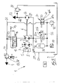
- a drive train 1 according to the invention of a mobile work machine not shown in detail, for example an industrial truck or a construction or agricultural machine, is shown in a schematic representation.
- the drive train 1 consists of an internal combustion engine 2, for example a diesel engine, a traction drive 3 of the vehicle driven by the internal combustion engine 2, and a working hydraulic system 4 driven by the internal combustion engine 2.
- an internal combustion engine 2 for example a diesel engine
- a traction drive 3 of the vehicle driven by the internal combustion engine 2 and a working hydraulic system 4 driven by the internal combustion engine 2.
- the travel drive 3 is designed as a hydrostatic travel drive, which consists of a drive pump 5 with an adjustable delivery volume, which is drive-connected to an output shaft 6 of the internal combustion engine 2 for driving purposes.
- the drive pump 5 is connected in a closed circuit to one or more hydraulic motors, which have a fixed or adjustable displacement volume and are not shown in detail, and which are operatively connected to the driven wheels of the machine in a way that is not shown.
- the traction drive 3 can alternatively be formed as an electric traction drive with an electric generator driven by the internal combustion engine 2 and one or more electric traction motors.
- a mechanical travel drive with a mechanical transmission for example a multi-step transmission or a power-split transmission or a torque converter transmission, can be provided as the travel drive.
- the working hydraulics system 4 includes working functions of the working machine, for example working hydraulics for operating a load handling device on a lifting mast in the case of an industrial truck, or in the case of an excavator, for example trained construction machine the working functions of the working equipment trained by a shovel.
- the working hydraulics system 4 comprises at least one hydraulic pump 7 operated in an open circuit, which is in driving connection with the output shaft 6 of the internal combustion engine 2 for driving purposes.
- the hydraulic pump 7 of the working hydraulic system 4 is in the embodiment figure 1 designed as a variable displacement pump with a variable displacement volume, for example as an axial piston machine with a swash plate design.
- the hydraulic pump 7 of the working hydraulic system 4 can alternatively be designed as a fixed displacement pump with a constant displacement volume.
- the hydraulic pump 7 On the inlet side, the hydraulic pump 7 is connected to the suction side by means of a suction line 8 with a container 9 .
- a delivery line 10 connected to the delivery side of the hydraulic pump 7 on the output side is connected to a control valve device, not shown in detail, by means of which the hydraulic consumers of the working hydraulic system 4, not shown in detail, can be controlled.
- the control valve device preferably includes one or more directional control valves for actuating the consumers.
- a priority valve 12 is also shown, with which the preferred supply of a consumer supplied by the hydraulic pump 7, for example a hydraulic steering device, can be ensured.
- the priority valve 12 is connected on the input side to the delivery side of the hydraulic pump 7 and on the output side is connected to the delivery line 10 leading to the working hydraulic system 4 and a delivery line 13 leading to the steering device.
- the priority valve 12 is controlled by a spring 14 and the load pressure of the steering device present in a load pressure line 15 .
- the drive train 1 also includes a feed pump 20 which is connected to the output shaft 6 for driving purposes.
- the feed pump 20 is designed as a constant displacement pump with a constant displacement volume, which is operated in an open circuit.
- the feed pump 20 is connected to the suction side via a suction line 21 with the container 9 and pumps into a feed pressure line 22 connected to the delivery side, to which the corresponding consumers of a feed circuit 23 are connected, for example adjustment devices for adjusting the Displacement volume of the drive pump 5 and the hydraulic pump 7, a feed device of the hydrostatic drive, a braking system of the vehicle and pilot valves for the control valves of the working hydraulic system 4.
- the feed pressure line 22 is assigned a pressure limiting device 24, for example a pressure limiting valve.
- the hydraulic pump 7 of the working hydraulic system 4 is designed as a two-quadrant drive mechanism which can be operated as a pump and motor with the same direction of rotation and the same direction of flow of the pressure medium.
- the hydraulic pump 7 draws in pressure medium from the container 9 via the intake line 8 and delivers the pressure medium via the priority valve 12 into the delivery line 10 of the working hydraulic system 4 or the delivery line 13 of the steering device.
- the hydraulic pump 7 is driven on the suction side with pressure medium from a pressure medium accumulator 25.
- the pressure medium reservoir 25 is connected to the delivery line 10 of the hydraulic pump 7 leading to the working hydraulic system 4 by means of a pressure medium line 26 for charging with pressure medium.
- an electrically actuable charging valve 27 which, when activated, can be actuated into a throttle position which throttles the delivery line 10 in order to build up a pressure.
- the loading valve 27 is preferably designed as a retarder valve 28, which is actuated into a throttle position when the vehicle is braking, in order to impose an additional, braking torque on the output shaft 6 formed by the crankshaft by building up pressure in the delivery line 10, which torque corresponds to the torque acting as a motor counteracts this at the drive pump 5 and thus brakes the vehicle.
- the pressure medium line 26 is connected to the delivery line 10 upstream of the charging valve 27 and thus between the charging valve 27 and the priority valve 12 .
- a shut-off valve 30 is arranged in the pressure medium line 26 and, in the exemplary embodiment shown, is designed as a non-return valve 31 that opens automatically and as a function of the pressure in the direction of the pressure medium accumulator 25 . Furthermore, the pressure medium line 26 between the check valve 30 and the pressure medium accumulator 25 is assigned a pressure relief valve 32 to secure the pressure in the pressure medium accumulator 25 . In the pressure medium line 26, a throttle device 33 is also arranged to limit the charging volume flow of the pressure medium accumulator 25, which can be designed as an orifice plate or throttle. The throttle device 33 can be arranged upstream of the shut-off valve 30 or alternatively downstream of the shut-off valve 30--as shown.
- the pressure medium line 26 between the check valve 30 and the pressure medium accumulator 25 is also associated with a pressure sensor 34 .
- the pressure sensor 34 is used to monitor the charging pressure and thus the charging status of the pressure fluid accumulator 25.
- the connection of the pressure medium accumulator 25 to the suction side of the hydraulic pump 7 for motor operation of the hydraulic pump 7 can be controlled by means of a first electrically actuatable control valve 35 .
- the control valve 35 has a blocking position 35a and a throughflow position 35b, the blocking position 35a preferably being designed to be leak-proof with a blocking valve blocking in the direction of the hydraulic pump 7 .
- the control valve 35 is arranged in a connecting line 36 which leads from the pressure medium line 26 between the check valve 30 and the pressure medium accumulator 25 to the suction line 8 leading to the suction side of the hydraulic pump 7 .
- shut-off valve 37 blocking in the direction of the container 9, which is preferably designed as a non-return valve 38 blocking in the direction of the container.
- the feed pump 20 is also designed as a two-quadrant drive mechanism which can be operated as a pump and motor with the same direction of rotation and the same direction of flow of the pressure medium.
- the feed pump 20 sucks in pressure medium from the container 9 with the intake line 21 connected to the suction side and pumps it into the feed pressure line 22 , which is connected to the delivery side of the feed pump 20 .
- feed pump 20 is designed in addition to hydraulic pump 7 as a hydraulic starter with a start-stop function for starting internal combustion engine 2 and/or as a booster drive to support running internal combustion engine 2, feed pump 7 driven on the suction side with pressure medium from the pressure medium reservoir 25.
- a second electrically actuable control valve 45 is provided to control the connection of the pressure medium reservoir 25 to the suction side of the feed pump 20 for motor operation of the feed pump 20 .
- the control valve 45 has a blocking position 45a and a throughflow position 45b, the blocking position 45a preferably being designed to be leak-proof with a blocking valve blocking in the direction of the feed pump 20 .
- the additional control valve 45 is arranged in a connecting line 46 which leads from the pressure medium line 26 between the check valve 30 and the pressure medium accumulator 25 to the intake line 21 of the feed pump 20 .
- shut-off valve 47 blocking in the direction of the tank 9 , which is preferably designed as a non-return valve 48 blocking in the direction of the tank 9 .
- An electronic control device 40 is connected to the pressure sensor 34 on the input side and serves to control the charging valve 27 as well as the first control valve 35 and the second control valve 45.
- FIG 2 an embodiment of a drive train 1 according to the invention is shown, in which the hydraulic pump 7 of the working hydraulic system 4 and the feed pump 20 have a common intake channel 50, which connects the suction side and thus the suction line 8 of the hydraulic pump 7 and the suction side and thus the suction line 21 of the feed pump 20 the container 9 connects.
- a blocking valve in the direction of the container 51 is arranged, which is preferably designed as a non-return valve 52 blocking in the direction of the container.
- a common electrically actuated control valve 55 is provided to control the connection of the suction sides of the hydraulic pump 7 and the feed pump 20 for motor operation of the two engines.
- the control valve 55 has a blocking position 55a and a throughflow position 55b, the blocking position 45a preferably being designed to be leak-proof with a blocking valve blocking in the direction of the intake passage 50 .
- the control valve 55 can be actuated by the electronic control device 40 .
- the common control valve 55 is arranged in a connecting line 56 which leads from the pressure medium line 26 between the check valve 30 and the pressure medium accumulator 25 to the common suction channel 50 of the hydraulic pump 7 and the feed pump 20 .
- the shut-off valve 30 is designed as an electrically actuated control valve 60 with a shut-off position 60a and a flow position 60b.
- the blocking position 60a is preferably designed to be leak-tight in both flow directions with a blocking valve blocking in the direction of the pressure medium reservoir 25 and a blocking valve blocking in the direction of the delivery line 10 .
- the control valve 60 can also be actuated by means of the electronic control device 40 .
- control valves 35, 45, 55 and the control valve 60 of Figures 1 to 3 can be designed as switching valves or as proportional valves that throttle in intermediate positions.
- the charging valve 27 is designed as a retarder valve 28 and is actuated into a throttle position when the vehicle is braking, since the kinetic energy of the braking vehicle is used to charge the pressure fluid accumulator 25 and energy can thus be recovered.
- the drive pump 5 works as a motor that drives the hydraulic pump 7 of the working hydraulics system 4, so that the pressure medium reservoir 25 can be charged with pressure medium via the retarder valve 28, which is actuated in the direction of the throttle position.
- the hydraulic pump 7 When the consumers of the working hydraulic system 4 are actuated, the hydraulic pump 7 thus promotes a delivery flow to actuate the consumers of the working hydraulic system 4 and also serves to deliver a delivery flow to charge the pressure fluid accumulator 25.
- the hydraulic pump 7 can be supplied on the primary side by that supplied by the internal combustion engine 2 performance are driven.
- the hydraulic pump 7 In conjunction with the retarder valve 28, the hydraulic pump 7 is driven to charge the pressure fluid accumulator 25 with the kinetic energy of the vehicle absorbed when the vehicle is decelerated in braking operation.
- the hydraulic pump 7 of the working hydraulic system 4 is used in engine operation as a hydraulic starter for the switched off internal combustion engine 2 in order to achieve a start-stop function.
- the control valve 35 is actuated to the flow position 35b.
- the check valve 37 in the intake line 8 prevents the pressure medium from flowing out of the pressure medium reservoir 25 into the container 9.
- a speed sensor (not shown in detail) connected to the control device 40 is provided, which is connected to the internal combustion engine 2 or the output shaft 6 is assigned, that is Control valve 35 is actuated in the blocking position 35a in order to prevent further emptying of the accumulator 25.
- the motor operation of the feed pump 20 can support the acceleration of the vehicle by the booster drive and the additional torque of the feed pump 20 by connecting the pressure fluid reservoir 25 to the feed pump 20 via the control valve 45 at the beginning of the acceleration process of the vehicle.
- the duration of the boost process can be limited as a function of the state of charge of the pressure fluid accumulator 25, which is detected by the pressure sensor 34. If there is still sufficient pressure medium in the pressure medium reservoir 25 at the end of the vehicle's acceleration process, the motor operation of the feed pump 20 can be maintained even when the vehicle is stationary at the target speed in order to use the torque from the booster drive of the feed pump 20.
- the internal combustion engine 2 can be supported with an additional torque from the booster drive of the feed pump 20 when actuating one or more consumers of the working hydraulic system 4, with the hydraulic pump 7 working as a pump .
Landscapes
- Engineering & Computer Science (AREA)
- General Engineering & Computer Science (AREA)
- Structural Engineering (AREA)
- Mechanical Engineering (AREA)
- Civil Engineering (AREA)
- Combustion & Propulsion (AREA)
- Chemical & Material Sciences (AREA)
- Mining & Mineral Resources (AREA)
- Transportation (AREA)
- Physics & Mathematics (AREA)
- Fluid Mechanics (AREA)
- Life Sciences & Earth Sciences (AREA)
- Geology (AREA)
- Automation & Control Theory (AREA)
- Fluid-Pressure Circuits (AREA)
Claims (22)
- Chaîne cinématique (1) d'un véhicule, notamment d'une machine de travail mobile, comportant un moteur à combustion interne (2) et un système hydraulique de travail (4) entraîné par le moteur à combustion interne (2), le système hydraulique de travail (4) comprenant des fonctions de travail de la machine de travail et présentant au moins une pompe hydraulique (7) entraînée par le moteur à combustion interne (2), laquelle peut fonctionner comme pompe et moteur, la pompe hydraulique (7), lors du fonctionnement comme pompe, aspirant un fluide sous pression hors d'un réservoir (9) par un côté d'aspiration et le refoulant dans une conduite de refoulement (10) guidée jusqu'au système hydraulique de travail (4) et, lors du fonctionnement comme moteur, du fluide sous pression pouvant être acheminé à la pompe hydraulique (7) à partir d'un accumulateur de fluide sous pression (25) sur le côté d'aspiration, caractérisée en ce que la chaîne cinématique (1) présente une pompe d'alimentation (20) entraînée par le moteur à combustion interne (2), laquelle alimente un circuit d'alimentation (23), le circuit d'alimentation (23) présentant une conduite sous pression d'alimentation (22) à laquelle sont raccordés les consommateurs du circuit d'alimentation (23), la pompe d'alimentation (20) pouvant fonctionner comme pompe et moteur, laquelle pompe d'alimentation, lors du fonctionnement comme pompe, aspire un fluide sous pression hors du réservoir (9) par un côté d'aspiration et le refoule dans la conduite sous pression d'alimentation (22) guidée jusqu'au circuit d'alimentation (23), et, lors du fonctionnement comme moteur, du fluide sous pression pouvant être acheminé à la pompe d'alimentation (20) à partir de l'accumulateur de fluide sous pression (25) sur le côté d'aspiration, une première soupape de commande (35) pouvant être actionnée électriquement étant prévue pour la commande de la liaison de l'accumulateur de fluide sous pression (25) au côté d'aspiration de la pompe hydraulique (7) et une deuxième soupape de commande (45) pouvant être actionnée électriquement étant prévue pour la commande de la liaison de l'accumulateur de fluide sous pression (25) au côté d'aspiration de la pompe d'alimentation (20) .
- Chaîne cinématique (1) d'un véhicule, notamment d'une machine de travail mobile, comportant un moteur à combustion interne (2) et un système hydraulique de travail (4) entraîné par le moteur à combustion interne (2), le système hydraulique de travail (4) comprenant des fonctions de travail de la machine de travail et présentant au moins une pompe hydraulique (7) entraînée par le moteur à combustion interne (2), laquelle peut fonctionner comme pompe et moteur, la pompe hydraulique (7), lors du fonctionnement comme pompe, aspirant un fluide sous pression hors d'un réservoir (9) par un côté d'aspiration et le refoulant dans une conduite de refoulement (10) guidée jusqu'au système hydraulique de travail (4) et, lors du fonctionnement comme moteur, du fluide sous pression pouvant être acheminé à la pompe hydraulique (7) à partir d'un accumulateur de fluide sous pression (25) sur le côté d'aspiration, caractérisée en ce que la chaîne cinématique (1) présente une pompe d'alimentation (20) entraînée par le moteur à combustion interne (2), laquelle alimente un circuit d'alimentation (23), le circuit d'alimentation (23) présentant une conduite sous pression d'alimentation (22) à laquelle sont raccordés les consommateurs du circuit d'alimentation (23), la pompe d'alimentation (20) pouvant fonctionner comme pompe et moteur, laquelle pompe d'alimentation, lors du fonctionnement comme pompe, aspire un fluide sous pression hors du réservoir (9) par un côté d'aspiration et le refoule dans la conduite sous pression d'alimentation (22) guidée jusqu'au circuit d'alimentation (23), et, lors du fonctionnement comme moteur, du fluide sous pression pouvant être acheminé à la pompe d'alimentation (20) à partir de l'accumulateur de fluide sous pression (25) sur le côté d'aspiration, une soupape de commande (55) commune pouvant être actionnée électriquement étant prévue pour la commande de la liaison de l'accumulateur de fluide sous pression (25) au côté d'aspiration de la pompe hydraulique (7) et pour la commande de la liaison de l'accumulateur de fluide sous pression (25) au côté d'aspiration de la pompe d'alimentation (20), laquelle soupape de commande commune est disposée dans une conduite de liaison (56) guidée à partir de l'accumulateur de fluide sous pression (25) jusqu'à un canal d'aspiration (50) commun de la pompe hydraulique (7) et de la pompe d'alimentation (20), le canal d'aspiration (50) commun reliant le côté d'aspiration de la pompe hydraulique (7) et le côté d'aspiration de la pompe d'alimentation (20) au réservoir (9) .
- Chaîne cinématique selon la revendication 1 ou 2, caractérisée en ce que la pompe hydraulique (7) est réalisée sous forme de démarreur hydraulique servant au démarrage du moteur à combustion interne (2) dans le cas d'une fonction Start-Stop.
- Chaîne cinématique selon l'une des revendications 1 à 3, caractérisée en ce que la pompe d'alimentation (20) est réalisée sous forme de démarreur hydraulique servant au démarrage du moteur à combustion interne (2) dans le cas d'une fonction Start-Stop et/ou sous forme d'entraînement d'appoint servant à assister le moteur à combustion interne (2) en marche.
- Chaîne cinématique selon la revendication 1, caractérisée en ce que la première soupape de commande (35) est disposée dans une conduite de liaison (36) guidée à partir de l'accumulateur de fluide sous pression (25) jusqu'à une conduite d'aspiration (8) de la pompe hydraulique (7), la conduite d'aspiration (8) étant guidée à partir du réservoir (9) jusqu'au côté d'aspiration de la pompe hydraulique (7).
- Chaîne cinématique selon la revendication 5, caractérisée en ce qu'une soupape d'arrêt (37) bloquant en direction du réservoir (9), en particulier une soupape anti-retour (38) bloquant en direction du réservoir, est disposée dans la conduite d'aspiration (8) guidée à partir du réservoir (9) jusqu'au côté d'aspiration de la pompe hydraulique (7).
- Chaîne cinématique selon l'une des revendications 1, 5 ou 6, caractérisée en ce que la deuxième soupape de commande (45) est disposée dans une conduite de liaison (46) guidée à partir de l'accumulateur de fluide sous pression (25) jusqu'à une conduite d'aspiration (21) de la pompe d'alimentation (20), la conduite d'aspiration (21) étant guidée à partir du réservoir (9) jusqu'au côté d'aspiration de la pompe d'alimentation (20).
- Chaîne cinématique selon la revendication 7, caractérisée en ce qu'une soupape d'arrêt (47) bloquant en direction du réservoir, en particulier une soupape anti-retour (48) bloquant en direction du réservoir (9), est disposée dans la conduite d'aspiration (21) guidée à partir du réservoir (9) jusqu'au côté d'aspiration de la pompe d'alimentation (20).
- Chaîne cinématique selon la revendication 2, caractérisée en ce qu'une soupape d'arrêt (51) bloquant en direction du réservoir (9), en particulier une soupape anti-retour (52) bloquant en direction du réservoir (9), est disposée dans le canal d'aspiration (50) commun.
- Chaîne cinématique selon l'une des revendications 1 à 9, caractérisée en ce que l'accumulateur de fluide sous pression (25) peut être raccordé à la conduite de refoulement (10) pour le chargement, une conduite de fluide sous pression (26) guidée jusqu'à l'accumulateur de fluide sous pression (25) étant raccordée à la conduite de refoulement (10) de la pompe hydraulique (7), laquelle conduite de refoulement est guidée jusqu'au système hydraulique de travail (4).
- Chaîne cinématique selon la revendication 10, caractérisée en ce qu'une soupape d'arrêt (30) est disposée dans la conduite de fluide sous pression (26).
- Chaîne cinématique selon la revendication 11, caractérisée en ce que la soupape d'arrêt (30) est réalisée sous forme de soupape anti-retour (31) s'ouvrant automatiquement et en fonction de la pression en direction de l'accumulateur de fluide sous pression (26) .
- Chaîne cinématique selon l'une des revendications 10 à 12, caractérisée en ce qu'un dispositif d'étranglement (33), en particulier un diaphragme ou un étranglement, est disposé dans la conduite de fluide sous pression (26).
- Chaîne cinématique selon la revendication 11, caractérisée en ce que la soupape d'arrêt (30) est réalisée sous forme de soupape de commande (60) pouvant être actionnée électriquement dotée d'une position d'arrêt (60a) et d'une position d'écoulement (60b).
- Chaîne cinématique selon l'une des revendications 1 à 14, caractérisée en ce qu'un capteur de pression (34) est associé à l'accumulateur de fluide sous pression (25) .
- Chaîne cinématique selon l'une des revendications 1 à 15, caractérisée en ce qu'une soupape de charge (27) étranglant la conduite de refoulement (10) et servant au chargement de l'accumulateur de fluide sous pression (25) est disposée dans la conduite de refoulement (10), guidée jusqu'au système hydraulique de travail (4), de la pompe hydraulique (7) et la conduite de fluide sous pression (26) est raccordée à la conduite refoulement (10) en amont de la soupape de charge (27).
- Chaîne cinématique selon la revendication 16, caractérisée en ce que la soupape de charge (27) est réalisée sous forme de soupape retardatrice (28) qui, lors du fonctionnement de freinage du véhicule, est actionnée dans une position d'étranglement étranglant la conduite de refoulement (10).
- Chaîne cinématique selon l'une des revendications 1 à 17, caractérisée en ce que la pompe hydraulique (7) est prévue pour l'alimentation d'un dispositif de direction hydraulique et une soupape de priorité (12) servant à l'alimentation préférée du système hydraulique de direction est associée au côté de refoulement de la pompe hydraulique (7), système hydraulique de direction auquel la conduite de refoulement (10) du système hydraulique de travail (4) est raccordée côté sortie.
- Chaîne cinématique selon l'une des revendications 1 à 17, caractérisée en ce que la pompe hydraulique (7) et/ou la pompe d'alimentation (20) fonctionne(nt) comme moteur pour le démarrage du moteur à combustion interne (2) .
- Chaîne cinématique selon l'une des revendications 1 à 19, caractérisée en ce que pour un entraînement d'appoint lorsque le moteur à combustion interne (2) est en marche, la pompe d'alimentation (20) fonctionne comme moteur.
- Chaîne cinématique selon l'une des revendications 1 à 20, caractérisée en ce que la pompe hydraulique (7) du système hydraulique de travail (4) est réalisée sous forme de pompe à cylindrée constante présentant un volume de refoulement fixe ou sous forme de pompe à cylindrée variable présentant un volume de refoulement réglable.
- Chaîne cinématique selon l'une des revendications 1 à 21, caractérisée en ce que la pompe hydraulique (7) est réalisée sous forme de machine à pistons axiaux ou sous forme de machine à pistons radiaux ou sous forme de machine à engrenages.
Applications Claiming Priority (1)
| Application Number | Priority Date | Filing Date | Title |
|---|---|---|---|
| DE102012111296.7A DE102012111296A1 (de) | 2012-11-22 | 2012-11-22 | Antriebsstrang eines Fahrzeugs, insbesondere einer mobilen Arbeitsmaschine |
Publications (2)
| Publication Number | Publication Date |
|---|---|
| EP2735657A1 EP2735657A1 (fr) | 2014-05-28 |
| EP2735657B1 true EP2735657B1 (fr) | 2022-08-10 |
Family
ID=49546283
Family Applications (1)
| Application Number | Title | Priority Date | Filing Date |
|---|---|---|---|
| EP13191528.2A Active EP2735657B1 (fr) | 2012-11-22 | 2013-11-05 | Chaîne cinématique d'un véhicule, notamment d'une machine de travail mobile |
Country Status (4)
| Country | Link |
|---|---|
| US (1) | US9745972B2 (fr) |
| EP (1) | EP2735657B1 (fr) |
| CN (1) | CN103836010B (fr) |
| DE (1) | DE102012111296A1 (fr) |
Families Citing this family (16)
| Publication number | Priority date | Publication date | Assignee | Title |
|---|---|---|---|---|
| JP6226758B2 (ja) * | 2014-01-22 | 2017-11-08 | 住友重機械工業株式会社 | ショベル及び建設機械 |
| DE102014109151A1 (de) * | 2014-06-30 | 2015-12-31 | Linde Material Handling Gmbh | Hydrostatisches Antriebssystem |
| DE102014110898A1 (de) * | 2014-07-31 | 2016-02-04 | Linde Material Handling Gmbh | Hydrostatisches Antriebssystem einer mobilen Arbeitsmaschine, insbesondere eines Flurförderzeugs |
| FR3016671B1 (fr) * | 2014-08-26 | 2016-01-22 | Poclain Hydraulics Ind | Dispositif de repartition d'huile avec clapet anti-retour |
| FR3026811B1 (fr) * | 2014-10-03 | 2016-12-09 | Poclain Hydraulics Ind | Procede d'assistance hydraulique de l'entrainement d'un vehicule a basse vitesse |
| DE102014118139A1 (de) | 2014-12-08 | 2016-06-09 | Linde Hydraulics Gmbh & Co. Kg | Hydrostatisches Antriebssystem |
| JP6496633B2 (ja) * | 2015-08-04 | 2019-04-03 | 株式会社豊田自動織機 | 産業車両 |
| JP6458703B2 (ja) * | 2015-10-13 | 2019-01-30 | 株式会社豊田自動織機 | 産業車両 |
| DE102016203713A1 (de) * | 2016-03-08 | 2017-09-14 | Robert Bosch Gmbh | Verfahren zur Steuerung für einen Verbrennungsmotor eines hydraulischen Hybridantriebs und elektronische Steuervorrichtung für einen Verbrennungsmotor eines hydraulischen Hybridantriebs und hydraulischer Hybridantrieb |
| CH712781A1 (de) * | 2016-07-18 | 2018-01-31 | Liebherr Machines Bulle Sa | Verdrängereinheit sowie hydraulisches Start-Stopp-System mit einer solchen Verdrängereinheit. |
| DE102016221126A1 (de) * | 2016-10-26 | 2018-04-26 | Zf Friedrichshafen Ag | Verfahren zum Durchführen eines Kaltstarts |
| CN111065535B (zh) * | 2017-09-08 | 2021-08-03 | 康明斯有限公司 | 用于发动机启动器和发电机的液压系统 |
| US11821442B2 (en) * | 2018-10-18 | 2023-11-21 | Volvo Construction Equipment Ab | Hydraulic energy handling system, a hydraulic parallel hybrid driveline and a working machine |
| EP3722617A1 (fr) * | 2019-04-08 | 2020-10-14 | Dana Italia S.r.L. | Circuit hydraulique |
| DE102022210736A1 (de) * | 2022-10-12 | 2024-04-18 | Bomag Gmbh | Verfahren zum abbremsen einer verdichtungsmaschine und verdichtungsmaschine |
| DE102024208524A1 (de) * | 2024-09-09 | 2026-03-12 | Robert Bosch Gesellschaft mit beschränkter Haftung | Hydraulisches Antriebssystem |
Citations (2)
| Publication number | Priority date | Publication date | Assignee | Title |
|---|---|---|---|---|
| WO2008009950A1 (fr) * | 2006-07-21 | 2008-01-24 | Artemis Intelligent Power Limited | Système hydraulique de distribution et de commande |
| WO2011041410A2 (fr) * | 2009-09-29 | 2011-04-07 | Purdue Research Foundation | Systèmes hydrauliques régénératifs et leurs procédés d'utilisation |
Family Cites Families (18)
| Publication number | Priority date | Publication date | Assignee | Title |
|---|---|---|---|---|
| DE2542244A1 (de) * | 1975-09-23 | 1977-03-31 | Langen & Co | Hydraulische anlage zum anlassen einer brennkraftmaschine |
| US4382484A (en) * | 1980-09-04 | 1983-05-10 | Advanced Energy Systems Inc. | Fuel-efficient energy storage automotive drive system |
| DE3247335A1 (de) * | 1981-12-21 | 1983-09-01 | Linde Ag, 6200 Wiesbaden | Antriebsaggreagt mit einer primaerenergiequelle und mit einer einrichtung zum bremsen |
| FR2708236A1 (fr) * | 1993-06-22 | 1995-02-03 | Man Nutzfahrzeuge Ag | Véhicule automobile avec un moteur à combustion interne et un entraînement hydrostatique-mécanique pour des équipements auxiliaires. |
| DE19852039A1 (de) * | 1998-11-11 | 2000-05-25 | Sauer Sundstrand Gmbh & Co | Hydrostatisch angetriebenes Fahrzeug mit Retarderventileinrichtung |
| DE19930056C1 (de) * | 1999-06-30 | 2001-01-25 | Sauer Sundstrand Gmbh & Co | Anordnung zum Steuern eines hydraulischen Fahrantriebs |
| JP4638362B2 (ja) * | 2006-02-21 | 2011-02-23 | 株式会社豊田中央研究所 | エンジン始動装置 |
| CN101037087A (zh) | 2006-03-14 | 2007-09-19 | 朱荣辉 | 一种机动车无级变速混合动力节能装置 |
| US20100122864A1 (en) | 2008-11-17 | 2010-05-20 | Allan Rosman | Hybrid hydraulic drive system for all terrestrial vehicles, with the hydraulic accumulator as the vehicle chassis |
| US20120060777A1 (en) * | 2009-01-22 | 2012-03-15 | Robert Bosch Gmbh | Hydrostatic Fan Drive |
| CN102549219B (zh) | 2009-09-15 | 2015-02-25 | 住友重机械工业株式会社 | 混合式施工机械 |
| DE102009048828A1 (de) | 2009-10-09 | 2011-04-14 | Linde Material Handling Gmbh | Hydraulische Vorrichtung und Verfahren zum Betrieb bei einer mobilen Arbeitsmaschine |
| CN102241379B (zh) * | 2010-05-13 | 2014-05-07 | 济南谨恒节能技术有限公司 | 节能型行走式液压搬运机械 |
| US20120233991A1 (en) | 2011-03-16 | 2012-09-20 | Purdue Research Foundtion | Multi-function machines, hydraulic systems therefor, and methods for their operation |
| DE102011105006A1 (de) | 2011-04-04 | 2012-10-04 | Linde Material Handling Gmbh | Antriebsstrang eines Fahrzeugs |
| DE102011104919A1 (de) * | 2011-04-04 | 2012-10-04 | Linde Material Handling Gmbh & Co. Kg | Antriebsstrang eines Fahrzeugs, insbesondere einer mobilen Arbeitsmaschine |
| DE102012111295A1 (de) * | 2012-11-22 | 2014-05-22 | Linde Hydraulics Gmbh & Co. Kg | Antriebsstrang eines Fahrzeugs |
| DE102015107857A1 (de) * | 2015-05-19 | 2016-11-24 | Linde Hydraulics Gmbh & Co. Kg | Hydrostatisches Antriebssystem |
-
2012
- 2012-11-22 DE DE102012111296.7A patent/DE102012111296A1/de not_active Withdrawn
-
2013
- 2013-11-05 EP EP13191528.2A patent/EP2735657B1/fr active Active
- 2013-11-18 US US14/082,428 patent/US9745972B2/en not_active Expired - Fee Related
- 2013-11-22 CN CN201310597140.7A patent/CN103836010B/zh not_active Expired - Fee Related
Patent Citations (2)
| Publication number | Priority date | Publication date | Assignee | Title |
|---|---|---|---|---|
| WO2008009950A1 (fr) * | 2006-07-21 | 2008-01-24 | Artemis Intelligent Power Limited | Système hydraulique de distribution et de commande |
| WO2011041410A2 (fr) * | 2009-09-29 | 2011-04-07 | Purdue Research Foundation | Systèmes hydrauliques régénératifs et leurs procédés d'utilisation |
Also Published As
| Publication number | Publication date |
|---|---|
| US9745972B2 (en) | 2017-08-29 |
| CN103836010A (zh) | 2014-06-04 |
| EP2735657A1 (fr) | 2014-05-28 |
| CN103836010B (zh) | 2018-06-05 |
| DE102012111296A1 (de) | 2014-05-22 |
| US20140212305A1 (en) | 2014-07-31 |
Similar Documents
| Publication | Publication Date | Title |
|---|---|---|
| EP2735657B1 (fr) | Chaîne cinématique d'un véhicule, notamment d'une machine de travail mobile | |
| EP2735656B1 (fr) | Chaîne cinématique d'un véhicule | |
| EP2840252B1 (fr) | Moteur hydrostatique | |
| DE102011104919A1 (de) | Antriebsstrang eines Fahrzeugs, insbesondere einer mobilen Arbeitsmaschine | |
| DE102011107061A1 (de) | Antriebsstrang eines Fahrzeugs, insbesondere einer mobilen Arbeitsmaschine | |
| EP2735726B1 (fr) | Moteur hydrostatique pour le démarrage d'un moteur à combustion | |
| DE102012010536A1 (de) | Hydraulisches System zurBremsenergierückgewinnung | |
| DE102011105006A1 (de) | Antriebsstrang eines Fahrzeugs | |
| EP3095999B1 (fr) | Systeme d'entrainement hydrostatique | |
| DE102012112381A1 (de) | Antriebsachse eines Fahrzeugs mit einer einen hydraulischen Druckmittelspeicher umfassenden Energierückgewinnungseinrichtung | |
| EP2735727B1 (fr) | Moteur hydrostatique en tant que démarreur hydraulique d'un moteur à combustion | |
| DE102011104921A1 (de) | Antriebsstrang einer mobilen Arbeitsmaschine | |
| DE102014001369B4 (de) | Mobile hydraulische Baumaschine | |
| DE102014109152A1 (de) | Hydrostatisches Antriebssystem einer mobilen Arbeitsmaschine | |
| EP2770192A2 (fr) | Dispositif de clapet anti-retour dans le côté aspiration d'une turbine hydrostatique pouvant fonctionner dans le même sens de rotation en tant que pompe et moteur | |
| EP2962883B9 (fr) | Système d'entraînement hydrostatique | |
| DE102012109376A1 (de) | Schmierölsystem zur Versorgung von motorinternen Schmierstellen eines eine Hydraulikanlage, insbesondere eine Arbeitshydraulik, antreibenden Verbrennungsmotors mit Schmieröl | |
| EP2980005A1 (fr) | Systeme d'entrainement hydrostatique d'une machine de travail mobile, notamment d'un chariot de manutention | |
| DE102014110900A1 (de) | Hydrostatisches Antriebssystem einer mobilen Arbeitsmaschine | |
| DE102015119471A1 (de) | Hydrostatisches Antriebssystem | |
| DE102014111824A1 (de) | Antriebssystem einer mobilen Arbeitsmaschine mit einer Speisepumpeneinrichtung | |
| DE102014114138A1 (de) | Hydrostatisches Antriebssystem | |
| DE102011107054A1 (de) | Antriebsstrang eines Fahrzeugs | |
| DE102014118139A1 (de) | Hydrostatisches Antriebssystem |
Legal Events
| Date | Code | Title | Description |
|---|---|---|---|
| PUAI | Public reference made under article 153(3) epc to a published international application that has entered the european phase |
Free format text: ORIGINAL CODE: 0009012 |
|
| 17P | Request for examination filed |
Effective date: 20131105 |
|
| AK | Designated contracting states |
Kind code of ref document: A1 Designated state(s): AL AT BE BG CH CY CZ DE DK EE ES FI FR GB GR HR HU IE IS IT LI LT LU LV MC MK MT NL NO PL PT RO RS SE SI SK SM TR |
|
| AX | Request for extension of the european patent |
Extension state: BA ME |
|
| R17P | Request for examination filed (corrected) |
Effective date: 20141127 |
|
| RBV | Designated contracting states (corrected) |
Designated state(s): AL AT BE BG CH CY CZ DE DK EE ES FI FR GB GR HR HU IE IS IT LI LT LU LV MC MK MT NL NO PL PT RO RS SE SI SK SM TR |
|
| STAA | Information on the status of an ep patent application or granted ep patent |
Free format text: STATUS: EXAMINATION IS IN PROGRESS |
|
| 17Q | First examination report despatched |
Effective date: 20200527 |
|
| REG | Reference to a national code |
Ref country code: DE Ref legal event code: R079 Ref document number: 502013016208 Country of ref document: DE Free format text: PREVIOUS MAIN CLASS: E02F0009220000 Ipc: B60K0006120000 |
|
| GRAP | Despatch of communication of intention to grant a patent |
Free format text: ORIGINAL CODE: EPIDOSNIGR1 |
|
| STAA | Information on the status of an ep patent application or granted ep patent |
Free format text: STATUS: GRANT OF PATENT IS INTENDED |
|
| RIC1 | Information provided on ipc code assigned before grant |
Ipc: B60W 20/19 20160101ALI20220428BHEP Ipc: F15B 1/033 20060101ALI20220428BHEP Ipc: F15B 1/02 20060101ALI20220428BHEP Ipc: F02N 11/08 20060101ALI20220428BHEP Ipc: F02N 7/08 20060101ALI20220428BHEP Ipc: F02N 7/00 20060101ALI20220428BHEP Ipc: E02F 9/22 20060101ALI20220428BHEP Ipc: B66F 9/22 20060101ALI20220428BHEP Ipc: B60K 6/12 20060101AFI20220428BHEP |
|
| INTG | Intention to grant announced |
Effective date: 20220518 |
|
| GRAS | Grant fee paid |
Free format text: ORIGINAL CODE: EPIDOSNIGR3 |
|
| GRAA | (expected) grant |
Free format text: ORIGINAL CODE: 0009210 |
|
| STAA | Information on the status of an ep patent application or granted ep patent |
Free format text: STATUS: THE PATENT HAS BEEN GRANTED |
|
| AK | Designated contracting states |
Kind code of ref document: B1 Designated state(s): AL AT BE BG CH CY CZ DE DK EE ES FI FR GB GR HR HU IE IS IT LI LT LU LV MC MK MT NL NO PL PT RO RS SE SI SK SM TR |
|
| REG | Reference to a national code |
Ref country code: GB Ref legal event code: FG4D Free format text: NOT ENGLISH |
|
| REG | Reference to a national code |
Ref country code: AT Ref legal event code: REF Ref document number: 1510263 Country of ref document: AT Kind code of ref document: T Effective date: 20220815 Ref country code: CH Ref legal event code: EP |
|
| REG | Reference to a national code |
Ref country code: DE Ref legal event code: R096 Ref document number: 502013016208 Country of ref document: DE |
|
| REG | Reference to a national code |
Ref country code: IE Ref legal event code: FG4D Free format text: LANGUAGE OF EP DOCUMENT: GERMAN |
|
| REG | Reference to a national code |
Ref country code: NL Ref legal event code: MP Effective date: 20220810 |
|
| REG | Reference to a national code |
Ref country code: LT Ref legal event code: MG9D |
|
| PG25 | Lapsed in a contracting state [announced via postgrant information from national office to epo] |
Ref country code: SE Free format text: LAPSE BECAUSE OF FAILURE TO SUBMIT A TRANSLATION OF THE DESCRIPTION OR TO PAY THE FEE WITHIN THE PRESCRIBED TIME-LIMIT Effective date: 20220810 Ref country code: RS Free format text: LAPSE BECAUSE OF FAILURE TO SUBMIT A TRANSLATION OF THE DESCRIPTION OR TO PAY THE FEE WITHIN THE PRESCRIBED TIME-LIMIT Effective date: 20220810 Ref country code: PT Free format text: LAPSE BECAUSE OF FAILURE TO SUBMIT A TRANSLATION OF THE DESCRIPTION OR TO PAY THE FEE WITHIN THE PRESCRIBED TIME-LIMIT Effective date: 20221212 Ref country code: NO Free format text: LAPSE BECAUSE OF FAILURE TO SUBMIT A TRANSLATION OF THE DESCRIPTION OR TO PAY THE FEE WITHIN THE PRESCRIBED TIME-LIMIT Effective date: 20221110 Ref country code: NL Free format text: LAPSE BECAUSE OF FAILURE TO SUBMIT A TRANSLATION OF THE DESCRIPTION OR TO PAY THE FEE WITHIN THE PRESCRIBED TIME-LIMIT Effective date: 20220810 Ref country code: LV Free format text: LAPSE BECAUSE OF FAILURE TO SUBMIT A TRANSLATION OF THE DESCRIPTION OR TO PAY THE FEE WITHIN THE PRESCRIBED TIME-LIMIT Effective date: 20220810 Ref country code: LT Free format text: LAPSE BECAUSE OF FAILURE TO SUBMIT A TRANSLATION OF THE DESCRIPTION OR TO PAY THE FEE WITHIN THE PRESCRIBED TIME-LIMIT Effective date: 20220810 Ref country code: FI Free format text: LAPSE BECAUSE OF FAILURE TO SUBMIT A TRANSLATION OF THE DESCRIPTION OR TO PAY THE FEE WITHIN THE PRESCRIBED TIME-LIMIT Effective date: 20220810 Ref country code: ES Free format text: LAPSE BECAUSE OF FAILURE TO SUBMIT A TRANSLATION OF THE DESCRIPTION OR TO PAY THE FEE WITHIN THE PRESCRIBED TIME-LIMIT Effective date: 20220810 |
|
| PG25 | Lapsed in a contracting state [announced via postgrant information from national office to epo] |
Ref country code: PL Free format text: LAPSE BECAUSE OF FAILURE TO SUBMIT A TRANSLATION OF THE DESCRIPTION OR TO PAY THE FEE WITHIN THE PRESCRIBED TIME-LIMIT Effective date: 20220810 Ref country code: IS Free format text: LAPSE BECAUSE OF FAILURE TO SUBMIT A TRANSLATION OF THE DESCRIPTION OR TO PAY THE FEE WITHIN THE PRESCRIBED TIME-LIMIT Effective date: 20221210 Ref country code: HR Free format text: LAPSE BECAUSE OF FAILURE TO SUBMIT A TRANSLATION OF THE DESCRIPTION OR TO PAY THE FEE WITHIN THE PRESCRIBED TIME-LIMIT Effective date: 20220810 Ref country code: GR Free format text: LAPSE BECAUSE OF FAILURE TO SUBMIT A TRANSLATION OF THE DESCRIPTION OR TO PAY THE FEE WITHIN THE PRESCRIBED TIME-LIMIT Effective date: 20221111 |
|
| PG25 | Lapsed in a contracting state [announced via postgrant information from national office to epo] |
Ref country code: SM Free format text: LAPSE BECAUSE OF FAILURE TO SUBMIT A TRANSLATION OF THE DESCRIPTION OR TO PAY THE FEE WITHIN THE PRESCRIBED TIME-LIMIT Effective date: 20220810 Ref country code: RO Free format text: LAPSE BECAUSE OF FAILURE TO SUBMIT A TRANSLATION OF THE DESCRIPTION OR TO PAY THE FEE WITHIN THE PRESCRIBED TIME-LIMIT Effective date: 20220810 Ref country code: DK Free format text: LAPSE BECAUSE OF FAILURE TO SUBMIT A TRANSLATION OF THE DESCRIPTION OR TO PAY THE FEE WITHIN THE PRESCRIBED TIME-LIMIT Effective date: 20220810 Ref country code: CZ Free format text: LAPSE BECAUSE OF FAILURE TO SUBMIT A TRANSLATION OF THE DESCRIPTION OR TO PAY THE FEE WITHIN THE PRESCRIBED TIME-LIMIT Effective date: 20220810 |
|
| REG | Reference to a national code |
Ref country code: DE Ref legal event code: R097 Ref document number: 502013016208 Country of ref document: DE |
|
| PG25 | Lapsed in a contracting state [announced via postgrant information from national office to epo] |
Ref country code: SK Free format text: LAPSE BECAUSE OF FAILURE TO SUBMIT A TRANSLATION OF THE DESCRIPTION OR TO PAY THE FEE WITHIN THE PRESCRIBED TIME-LIMIT Effective date: 20220810 Ref country code: EE Free format text: LAPSE BECAUSE OF FAILURE TO SUBMIT A TRANSLATION OF THE DESCRIPTION OR TO PAY THE FEE WITHIN THE PRESCRIBED TIME-LIMIT Effective date: 20220810 |
|
| PLBE | No opposition filed within time limit |
Free format text: ORIGINAL CODE: 0009261 |
|
| STAA | Information on the status of an ep patent application or granted ep patent |
Free format text: STATUS: NO OPPOSITION FILED WITHIN TIME LIMIT |
|
| P01 | Opt-out of the competence of the unified patent court (upc) registered |
Effective date: 20230514 |
|
| PG25 | Lapsed in a contracting state [announced via postgrant information from national office to epo] |
Ref country code: MC Free format text: LAPSE BECAUSE OF FAILURE TO SUBMIT A TRANSLATION OF THE DESCRIPTION OR TO PAY THE FEE WITHIN THE PRESCRIBED TIME-LIMIT Effective date: 20220810 Ref country code: AL Free format text: LAPSE BECAUSE OF FAILURE TO SUBMIT A TRANSLATION OF THE DESCRIPTION OR TO PAY THE FEE WITHIN THE PRESCRIBED TIME-LIMIT Effective date: 20220810 |
|
| REG | Reference to a national code |
Ref country code: CH Ref legal event code: PL |
|
| 26N | No opposition filed |
Effective date: 20230511 |
|
| GBPC | Gb: european patent ceased through non-payment of renewal fee |
Effective date: 20221110 |
|
| REG | Reference to a national code |
Ref country code: BE Ref legal event code: MM Effective date: 20221130 |
|
| PG25 | Lapsed in a contracting state [announced via postgrant information from national office to epo] |
Ref country code: LI Free format text: LAPSE BECAUSE OF NON-PAYMENT OF DUE FEES Effective date: 20221130 Ref country code: CH Free format text: LAPSE BECAUSE OF NON-PAYMENT OF DUE FEES Effective date: 20221130 |
|
| PG25 | Lapsed in a contracting state [announced via postgrant information from national office to epo] |
Ref country code: SI Free format text: LAPSE BECAUSE OF FAILURE TO SUBMIT A TRANSLATION OF THE DESCRIPTION OR TO PAY THE FEE WITHIN THE PRESCRIBED TIME-LIMIT Effective date: 20220810 Ref country code: LU Free format text: LAPSE BECAUSE OF NON-PAYMENT OF DUE FEES Effective date: 20221105 |
|
| PG25 | Lapsed in a contracting state [announced via postgrant information from national office to epo] |
Ref country code: IE Free format text: LAPSE BECAUSE OF NON-PAYMENT OF DUE FEES Effective date: 20221105 Ref country code: GB Free format text: LAPSE BECAUSE OF NON-PAYMENT OF DUE FEES Effective date: 20221110 |
|
| PG25 | Lapsed in a contracting state [announced via postgrant information from national office to epo] |
Ref country code: FR Free format text: LAPSE BECAUSE OF NON-PAYMENT OF DUE FEES Effective date: 20221130 Ref country code: BE Free format text: LAPSE BECAUSE OF NON-PAYMENT OF DUE FEES Effective date: 20221130 |
|
| REG | Reference to a national code |
Ref country code: AT Ref legal event code: MM01 Ref document number: 1510263 Country of ref document: AT Kind code of ref document: T Effective date: 20221105 |
|
| PG25 | Lapsed in a contracting state [announced via postgrant information from national office to epo] |
Ref country code: AT Free format text: LAPSE BECAUSE OF NON-PAYMENT OF DUE FEES Effective date: 20221105 |
|
| PG25 | Lapsed in a contracting state [announced via postgrant information from national office to epo] |
Ref country code: HU Free format text: LAPSE BECAUSE OF FAILURE TO SUBMIT A TRANSLATION OF THE DESCRIPTION OR TO PAY THE FEE WITHIN THE PRESCRIBED TIME-LIMIT; INVALID AB INITIO Effective date: 20131105 |
|
| PG25 | Lapsed in a contracting state [announced via postgrant information from national office to epo] |
Ref country code: CY Free format text: LAPSE BECAUSE OF FAILURE TO SUBMIT A TRANSLATION OF THE DESCRIPTION OR TO PAY THE FEE WITHIN THE PRESCRIBED TIME-LIMIT Effective date: 20220810 |
|
| PG25 | Lapsed in a contracting state [announced via postgrant information from national office to epo] |
Ref country code: MK Free format text: LAPSE BECAUSE OF FAILURE TO SUBMIT A TRANSLATION OF THE DESCRIPTION OR TO PAY THE FEE WITHIN THE PRESCRIBED TIME-LIMIT Effective date: 20220810 Ref country code: IT Free format text: LAPSE BECAUSE OF FAILURE TO SUBMIT A TRANSLATION OF THE DESCRIPTION OR TO PAY THE FEE WITHIN THE PRESCRIBED TIME-LIMIT Effective date: 20220810 |
|
| PG25 | Lapsed in a contracting state [announced via postgrant information from national office to epo] |
Ref country code: BG Free format text: LAPSE BECAUSE OF FAILURE TO SUBMIT A TRANSLATION OF THE DESCRIPTION OR TO PAY THE FEE WITHIN THE PRESCRIBED TIME-LIMIT Effective date: 20220810 |
|
| PG25 | Lapsed in a contracting state [announced via postgrant information from national office to epo] |
Ref country code: MT Free format text: LAPSE BECAUSE OF FAILURE TO SUBMIT A TRANSLATION OF THE DESCRIPTION OR TO PAY THE FEE WITHIN THE PRESCRIBED TIME-LIMIT Effective date: 20220810 |
|
| PGFP | Annual fee paid to national office [announced via postgrant information from national office to epo] |
Ref country code: DE Payment date: 20241119 Year of fee payment: 12 |
|
| REG | Reference to a national code |
Ref country code: DE Ref legal event code: R081 Ref document number: 502013016208 Country of ref document: DE Owner name: LHY POWERTRAIN GMBH & CO. KG, DE Free format text: FORMER OWNER: LINDE HYDRAULICS GMBH & CO. KG, 63743 ASCHAFFENBURG, DE |
|
| PG25 | Lapsed in a contracting state [announced via postgrant information from national office to epo] |
Ref country code: TR Free format text: LAPSE BECAUSE OF FAILURE TO SUBMIT A TRANSLATION OF THE DESCRIPTION OR TO PAY THE FEE WITHIN THE PRESCRIBED TIME-LIMIT Effective date: 20220810 |