EP2770192A2 - Dispositif de clapet anti-retour dans le côté aspiration d'une turbine hydrostatique pouvant fonctionner dans le même sens de rotation en tant que pompe et moteur - Google Patents
Dispositif de clapet anti-retour dans le côté aspiration d'une turbine hydrostatique pouvant fonctionner dans le même sens de rotation en tant que pompe et moteur Download PDFInfo
- Publication number
- EP2770192A2 EP2770192A2 EP20140153079 EP14153079A EP2770192A2 EP 2770192 A2 EP2770192 A2 EP 2770192A2 EP 20140153079 EP20140153079 EP 20140153079 EP 14153079 A EP14153079 A EP 14153079A EP 2770192 A2 EP2770192 A2 EP 2770192A2
- Authority
- EP
- European Patent Office
- Prior art keywords
- engine
- check valve
- pressure
- valve
- hydrostatic
- Prior art date
- Legal status (The legal status is an assumption and is not a legal conclusion. Google has not performed a legal analysis and makes no representation as to the accuracy of the status listed.)
- Withdrawn
Links
Images


Classifications
-
- F—MECHANICAL ENGINEERING; LIGHTING; HEATING; WEAPONS; BLASTING
- F02—COMBUSTION ENGINES; HOT-GAS OR COMBUSTION-PRODUCT ENGINE PLANTS
- F02B—INTERNAL-COMBUSTION PISTON ENGINES; COMBUSTION ENGINES IN GENERAL
- F02B73/00—Combinations of two or more engines, not otherwise provided for
-
- B—PERFORMING OPERATIONS; TRANSPORTING
- B60—VEHICLES IN GENERAL
- B60K—ARRANGEMENT OR MOUNTING OF PROPULSION UNITS OR OF TRANSMISSIONS IN VEHICLES; ARRANGEMENT OR MOUNTING OF PLURAL DIVERSE PRIME-MOVERS IN VEHICLES; AUXILIARY DRIVES FOR VEHICLES; INSTRUMENTATION OR DASHBOARDS FOR VEHICLES; ARRANGEMENTS IN CONNECTION WITH COOLING, AIR INTAKE, GAS EXHAUST OR FUEL SUPPLY OF PROPULSION UNITS IN VEHICLES
- B60K6/00—Arrangement or mounting of plural diverse prime-movers for mutual or common propulsion, e.g. hybrid propulsion systems comprising electric motors and internal combustion engines
- B60K6/08—Prime-movers comprising combustion engines and mechanical or fluid energy storing means
- B60K6/12—Prime-movers comprising combustion engines and mechanical or fluid energy storing means by means of a chargeable fluidic accumulator
-
- B—PERFORMING OPERATIONS; TRANSPORTING
- B60—VEHICLES IN GENERAL
- B60W—CONJOINT CONTROL OF VEHICLE SUB-UNITS OF DIFFERENT TYPE OR DIFFERENT FUNCTION; CONTROL SYSTEMS SPECIALLY ADAPTED FOR HYBRID VEHICLES; ROAD VEHICLE DRIVE CONTROL SYSTEMS FOR PURPOSES NOT RELATED TO THE CONTROL OF A PARTICULAR SUB-UNIT
- B60W10/00—Conjoint control of vehicle sub-units of different type or different function
- B60W10/04—Conjoint control of vehicle sub-units of different type or different function including control of propulsion units
- B60W10/06—Conjoint control of vehicle sub-units of different type or different function including control of propulsion units including control of combustion engines
-
- B—PERFORMING OPERATIONS; TRANSPORTING
- B60—VEHICLES IN GENERAL
- B60W—CONJOINT CONTROL OF VEHICLE SUB-UNITS OF DIFFERENT TYPE OR DIFFERENT FUNCTION; CONTROL SYSTEMS SPECIALLY ADAPTED FOR HYBRID VEHICLES; ROAD VEHICLE DRIVE CONTROL SYSTEMS FOR PURPOSES NOT RELATED TO THE CONTROL OF A PARTICULAR SUB-UNIT
- B60W30/00—Purposes of road vehicle drive control systems not related to the control of a particular sub-unit, e.g. of systems using conjoint control of vehicle sub-units
- B60W30/18—Propelling the vehicle
- B60W30/18009—Propelling the vehicle related to particular drive situations
- B60W30/18018—Start-stop drive, e.g. in a traffic jam
-
- F—MECHANICAL ENGINEERING; LIGHTING; HEATING; WEAPONS; BLASTING
- F02—COMBUSTION ENGINES; HOT-GAS OR COMBUSTION-PRODUCT ENGINE PLANTS
- F02N—STARTING OF COMBUSTION ENGINES; STARTING AIDS FOR SUCH ENGINES, NOT OTHERWISE PROVIDED FOR
- F02N7/00—Starting apparatus having fluid-driven auxiliary engines or apparatus
-
- B—PERFORMING OPERATIONS; TRANSPORTING
- B60—VEHICLES IN GENERAL
- B60K—ARRANGEMENT OR MOUNTING OF PROPULSION UNITS OR OF TRANSMISSIONS IN VEHICLES; ARRANGEMENT OR MOUNTING OF PLURAL DIVERSE PRIME-MOVERS IN VEHICLES; AUXILIARY DRIVES FOR VEHICLES; INSTRUMENTATION OR DASHBOARDS FOR VEHICLES; ARRANGEMENTS IN CONNECTION WITH COOLING, AIR INTAKE, GAS EXHAUST OR FUEL SUPPLY OF PROPULSION UNITS IN VEHICLES
- B60K6/00—Arrangement or mounting of plural diverse prime-movers for mutual or common propulsion, e.g. hybrid propulsion systems comprising electric motors and internal combustion engines
- B60K6/08—Prime-movers comprising combustion engines and mechanical or fluid energy storing means
- B60K6/12—Prime-movers comprising combustion engines and mechanical or fluid energy storing means by means of a chargeable fluidic accumulator
- B60K2006/126—Prime-movers comprising combustion engines and mechanical or fluid energy storing means by means of a chargeable fluidic accumulator the hydraulic accumulator starts the engine
-
- Y—GENERAL TAGGING OF NEW TECHNOLOGICAL DEVELOPMENTS; GENERAL TAGGING OF CROSS-SECTIONAL TECHNOLOGIES SPANNING OVER SEVERAL SECTIONS OF THE IPC; TECHNICAL SUBJECTS COVERED BY FORMER USPC CROSS-REFERENCE ART COLLECTIONS [XRACs] AND DIGESTS
- Y02—TECHNOLOGIES OR APPLICATIONS FOR MITIGATION OR ADAPTATION AGAINST CLIMATE CHANGE
- Y02T—CLIMATE CHANGE MITIGATION TECHNOLOGIES RELATED TO TRANSPORTATION
- Y02T10/00—Road transport of goods or passengers
- Y02T10/60—Other road transportation technologies with climate change mitigation effect
- Y02T10/62—Hybrid vehicles
-
- Y—GENERAL TAGGING OF NEW TECHNOLOGICAL DEVELOPMENTS; GENERAL TAGGING OF CROSS-SECTIONAL TECHNOLOGIES SPANNING OVER SEVERAL SECTIONS OF THE IPC; TECHNICAL SUBJECTS COVERED BY FORMER USPC CROSS-REFERENCE ART COLLECTIONS [XRACs] AND DIGESTS
- Y10—TECHNICAL SUBJECTS COVERED BY FORMER USPC
- Y10T—TECHNICAL SUBJECTS COVERED BY FORMER US CLASSIFICATION
- Y10T137/00—Fluid handling
- Y10T137/7722—Line condition change responsive valves
- Y10T137/7837—Direct response valves [i.e., check valve type]
Definitions
- the invention relates to a check valve device of a hydrostatic engine, which is drivingly connected to an internal combustion engine and is operable as a pump and motor, the engine sucks in pumping operation with a suction side pressure medium from a container and promotes delivery side and wherein the engine in the engine operation of the Suction side, which is in communication with the container, supplied and pressurized pressure fluid is driven from a pressure fluid reservoir, wherein the check valve device is arranged in the suction side of the hydrostatic engine to achieve a pressure build-up on the suction side in engine operation.
- Mobile self-propelled machines especially industrial trucks, agricultural machinery, forestry machinery and construction equipment, such as excavators, wheeled and telescopic loaders, tractors, combine harvester, forage harvester, sugar beet or potato harvester, have a drive train with an internal combustion engine, a traction drive and a working hydraulic system for the working functions of Working machine drives.
- To supply the working hydraulic system at least one of the internal combustion engine driven hydraulic pump is provided.
- the internal combustion engine is operated at a lower idling speed. Such idling operation takes place during work breaks or during work stoppages.
- hydrostatic engines are used as hydraulic starters of the internal combustion engine for a start-stop function, which are drivingly connected to the crankshaft of the internal combustion engine and operated with pressure medium from a precharged before stopping the internal combustion engine accumulator during a starting operation of the internal combustion engine.
- a powertrain is known in which, in addition to the hydraulic pump of the working hydraulic system, a further hydraulic motor is provided as a starter of the internal combustion engine for a start-stop function of the internal combustion engine. Since such an additional hydraulic motor is dragged in the drive train during normal operation of the current internal combustion engine, losses occur that reduce the overall efficiency of the working machine.
- such an additional hydraulic motor as a starter of the internal combustion engine causes additional construction costs and space requirements.
- the hydraulic pump of the working hydraulic system is designed as a hydraulic pump operated in open circuit, which communicates with a suction connection for the pressure medium via a suction side with a container and conveys the pressure medium into a delivery line connected to a delivery connection.
- the hydraulic pump In pump operation, in which the hydraulic pump is driven by the running internal combustion engine, the hydraulic pump sucks Pressure medium via the suction side of the container and promotes this to supply the load of the working hydraulic system in the delivery line. If the hydraulic pump is pressurized on the suction side with pressure medium under pressure from a pressure medium reservoir, the hydraulic pump operates at the same direction of rotation of the hydrostatic engine and the same flow direction of the pressure medium as an engine, which allows, on the crankshaft of the internal combustion engine, a torque for starting the internal combustion engine in the frame To generate a start-stop function and / or deliver an additional torque to the crankshaft with the internal combustion engine to relieve the current engine in the context of a booster drive and support.
- the booster drive by the engine operation of the hydraulic pump of the working hydraulic system with the engine running makes it possible to reduce the fuel consumption of the internal combustion engine.
- the combustion engine can be reduced in its power by the hydrostatic booster drive.
- Such a downsizing of the internal combustion engine leads to advantages, in particular in the observance of legal exhaust gas regulations of the internal combustion engine.
- FIGS. 1 . 2 of the WO 2012/125798 A1 and the EP 2 308 795 A1 are designed as working hydraulic pumps hydrostatic engines known that are used in pump operation to supply the load of a working hydraulic system and can be used in the same direction of rotation in engine operation as a hydraulic starter and / or booster drive of the engine.
- a non-return valve closing in the direction of the container is arranged in the suction side.
- the hydraulic pump for example an axial piston machine, of the working hydraulic system is generally designed for a high suction limit speed for pump operation.
- the suction side connected to the container during pump operation and the suction connection of the hydrostatic engine have a correspondingly large cross section.
- Both FIGS. 1 . 2 of the WO 2012/125798 A1 and the EP 2 308 795 A1 is arranged in the suction side of the hydrostatic engine and blocking in the direction of the container check valve as a conventional, pressure-actuated check valve, such as ball check valve is formed, which is controlled in the pump operation of the engine by the resulting suction pressure in the suction side in an open position.
- the present invention has for its object, in the suction side of a hydrostatic engine, which is operated in the same direction of rotation as a pump and motor, wherein the engine is supplied in engine operation pressure fluid from a pressure fluid reservoir on the suction side, arranged check valve device to provide the In pump operation of the engine with open check valve device, the Sauggrenzfaniere the engine is not affected.
- the check valve device comprises an actuatable by means of an actuator check valve, wherein by means of the actuator, the check valve active between a shut-off, in which a connection of the suction side is shut off with the container in the flow direction from the suction side to the container, and a Open position is actuated, in which the connection of the suction side is open with the container.
- a hydrostatic engine which serves to supply a consumer, for example a working hydraulic system, can be used during engine operation as a hydraulic starter of the internal combustion engine and / or as a booster drive to assist the internal combustion engine. without having a reduced suction limit speed during pump operation.
- the check valve by means of the actuator in the pump operation of the engine in the open position and in engine operation of the engine in the shut-off position is actuated.
- the actuator it is easily possible to actively control the check valve to the open position during pump operation to achieve pump operation of the hydrostatic engine without additional flow resistances in the suction side and to actively actuate the hydrostatic engine check valve to the shut-off position to allow a drive of the engine via the supplied from the pressure medium accumulator suction side pressure medium.
- the check valve by means of a spring device in the shut-off position is actuated and the check valve is actuated by an actuating device acting hydraulic actuating pressure in the open position.
- the non-return valve located in the shut-off position is acted upon by the pending in the suction side pressure of the accumulator in the shut-off. This ensures that the check valve is held during the duration of the starting process of the internal combustion engine of the pending pressure in the suction side of the accumulator in the shut-off position and thus prevents the check valve operated before the end of the starting process of the operating pressure generated during operation of the internal combustion engine in the open position becomes.
- the actuating device is designed as a standing with the check valve operatively connected actuating piston.
- an actuating piston With an actuating piston, an active actuation of the check valve between the shut-off position and the open position can be achieved in a simple manner.
- the actuating piston is acted upon according to an expedient embodiment of the invention by the spring device and has a loadable with the actuating pressure piston pressure chamber, which counteracts the spring means.
- This can be achieved with low construction costs, that the check valve is actuated by the spring means in the shut-off position and by means of the actuating pressure in the open position.
- the spring device is arranged in a spring-side piston pressure chamber of the actuating piston, which is connectable to the container. With pending actuation pressure thus the actuating piston can be moved against the force of the spring means and thereby the check valve can be actuated in the open position.
- the actuator is designed as arranged on the check valve, acted upon by the hydraulic actuating pressure control pressure surface, the the check valve is actuated in the direction of the open position.
- the check valve is designed as a flap valve with a pivotable flap, which is in operative connection with the actuating device.
- a flap valve allows a compact and space-saving design of the check valve and can be operated with low construction costs with a trained as a control piston actuation direction.
- a flap valve is also achieved in a simple manner that the flap valve located in the shut-off position is held in a starting operation of the internal combustion engine of the pending on the suction side of the engine pressure of the accumulator in the shut-off position.
- the adjusting piston with the interposition of a hinged on the flap and on the Stellkoben hinged coupling rod, in particular a rocker, are in operative connection with the flap.
- a hinged coupling rod can be easily actuated by the linear movement of the actuating piston, the pivotable flap of the flap valve.
- the actuating piston can be connected directly to the flap in an articulated manner, wherein the articulated connection comprises a slot. If the articulated connection between the actuating piston and the pivotable flap comprises a slot, the pivotable flap of the flap valve can also be actuated in a simple manner by linear movement of the actuating piston.
- the flap is pivotably arranged in a suction channel in such a way that the flap does not dive into the suction channel in the open position. This ensures that the flap located in the open position no additional hydraulic Resistance and thus no additional flow resistance caused in the suction side of the engine during pump operation.
- the check valve is designed as a flat slide valve with a longitudinally displaceable slider, which is in operative connection with the actuating device.
- a flat slide valve also allows a compact and space-saving design of the check valve and can be operated with low construction costs with a trained as a control piston or as a control pressure surface actuation direction.
- a flat slide valve can be achieved in a simple manner that the slide in the open position causes no additional flow resistance in the suction side of the engine during pump operation.
- the check valve is designed as a piston slide valve with a longitudinally displaceable or rotatable piston, which is in operative connection with the actuating device.
- a piston valve also allows a compact and space-saving design of the check valve and can be operated with low construction costs with a trained as a control piston or as a control pressure surface actuation direction.
- it can be achieved in a piston valve in a simple manner that the preferably cylindrical piston in the open position causes no additional flow resistance in the suction side of the engine during pump operation.
- the check valve is designed as a ball valve with a rotatable ball, which is in operative connection with the actuating device.
- a ball valve also allows a compact and space-saving design of the check valve and can be operated with low construction costs with a trained as a control piston or as a control pressure surface actuation direction.
- it can be achieved in a ball valve in a simple manner that the ball in the open position causes no additional flow resistance in the suction side of the engine during pump operation.
- the invention further relates to a hydrostatic engine, which is drivingly connected to an internal combustion engine and is operable as a pump and a motor, wherein the engine in pump mode with a suction side sucks pressure medium from a container and promotes delivery side and wherein the engine is driven in engine operation of the suction side, which communicates with the container, supplied and under pressure pressure medium from a pressure fluid reservoir, wherein a Check valve device according to the invention is arranged in the suction side of the hydrostatic engine.
- a motor operation of the engine can be achieved to the engine as a hydraulic starter of the engine at a start-stop Function and / or as a booster drive to support the running internal combustion engine.
- the suction side of the hydrostatic engine can be designed here as a suction or suction line.
- the check valve device is installed in a housing of the engine.
- the check valve device can thereby be integrated with little structural effort in the housing of the engine and are arranged in the housing formed in the portion of the suction channel.
- the check valve device may have an independent housing. This makes it possible in a simple manner to supplement the inventive check valve device in an existing engine to achieve the additional engine operation of the engine for the function of the hydraulic starter and / or the function of the booster drive.
- the housing of the check valve device can in this case be flanged to the housing of the engine. If the housing of the check valve device is designed such that it can be flanged to the housing of the engine in the region of the suction port, with little additional construction costs, an existing engine with the check valve device according to the invention can be provided to the additional engine operation of Engine for the function of the hydraulic starter and / or to achieve the function of the booster drive.
- a control valve is provided to control the connection of the accumulator with the suction side of the engine for engine operation, the suction side of the engine can be easily connected in engine operation with the accumulator.
- the engine can be designed as a constant displacement engine in the displacement volume.
- the engine can be designed as an adjusting drive that is more adjustable in the displacer volume, wherein the displacer volume can be adjusted by means of a displacer volume adjusting device which can be actuated by means of an adjusting device, wherein the adjusting device is connected to a feed pressure circuit for supplying pressurized fluid and can be connected to the accumulator.
- a hydraulic or electro-hydraulic adjusting device can be supplied by the connection with a feed pressure circuit and / or the pressure medium storage in a simple manner with pressure means for adjusting and actuating the displacement volume adjusting device.
- connection of the adjusting device with the accumulator allows in a simple manner that the engine displacement control of the engine for the starting process of the parked internal combustion engine in the direction of the maximum displacement volume can be adjusted with pressure fluid from the charged pressure fluid reservoir in the engine operation of the engine used as a hydraulic starter by the to generate a corresponding torque for starting the internal combustion engine from the pressure fluid reservoir of the suction side inflowing pressure medium.
- this is in the connection of the adjusting device with the feed pressure circuit a check valve, in particular a blocking in the direction of the feed pressure circuit check valve arranged.
- the pressure fluid accumulator is expediently connected to the intake side of the engine by means of a connecting line in which the control valve is arranged, wherein a pressure medium line is provided for supplying the actuating device with pressure medium from the pressure fluid accumulator, which between the control valve and the suction side of the engine to the connecting line connected.
- the pressure medium line is connected to a guided from the feed pressure circuit to the actuating device actuating pressure line in which the check valve is arranged, wherein the pressure medium line between the check valve and the adjusting device is connected to the control pressure line.
- a pressure reducing valve is arranged in the pressure medium line, whereby the pressure level existing in the accumulator memory can be reduced to the level of the feed pressure for supplying the adjusting device of the engine with little additional construction costs.
- the feed pressure of a feed pressure circuit is formed as the actuating pressure of the actuating device of the check valve.
- a hydrostatic actuation of the actuating device and thus of the check valve can be achieved in a simple manner and with low construction costs.
- a guided from the pressure medium line to the actuator branch line is expediently provided, wherein between the pressure reducing valve and the connection of the branch line a check valve, in particular a blocking in the direction of the pressure reducing valve check valve is arranged.
- branched off from the pressure medium line branch line is achieved that is present at a starting operation of the pressure reduction valve generated feed pressure in the branch line and after the starting process with the engine running the feed pressure of the feed pressure circuit actuates the actuator to the check valve in pump operation in the open position Press and hold in the open position.
- the piston pressure chamber of the actuating piston is connected to the feed pressure circuit and the spring-side piston pressure chamber of the actuating piston is relieved to the container.
- a connection of the actuating piston is achieved without additional control valves and a control logic functionality of the check valve for the use of the engine during engine operation as a hydraulic starter of the engine, wherein the check valve is actuated with the engine off by means of the spring device in the shut-off and running engine is actuated by the generated feed pressure of the feed pressure circuit in the open position.
- control pressure surface of the check valve is connected to the feed pressure circuit and another control pressure surface is formed on the check valve, which actuates the check valve in the direction of the shut-off, the further control pressure surface for pressurizing with the suction side between the engine and the check valve connectable is.
- a changeover valve for controlling the actuation of the actuating device, by means of which in a first switching position, the check valve in response to the operating pressure in the open position is actuated by means of the check valve in a second switching position is actuated in the shut-off position.
- the first switching position of the switching valve thus the functionality of the check valve for the use of the engine during engine operation is achieved as a hydraulic starter of the internal combustion engine.
- the second switching position of the switching valve is made possible to operate with the internal combustion engine, the check valve in the shut-off position to achieve a functionality of the check valve for the use of the engine during engine operation as a booster drive with the internal combustion engine running.
- the piston pressure chamber of the actuating piston is acted upon in the first switching position of the switching valve with the actuating pressure and the spring-side piston pressure chamber relieved to the container and in the second switching position of the switching valve of the spring-side piston pressure chamber of the actuating piston acted upon by the actuating pressure and the piston pressure chamber relieved to the container.
- the first switching position of the switching valve thus the functionality of the check valve for the use of the engine during engine operation is achieved as a hydraulic starter of the internal combustion engine.
- the check valve In the second switching position of the changeover valve is allowed to operate with the internal combustion engine, the check valve from the spring-side piston pressure chamber of the actuator piston acting boost pressure in the shut-off to achieve functionality of the check valve for the use of the engine in engine operation as a booster drive with the internal combustion engine ,
- the functionality of the check valve for the use of the engine in engine operation as a hydraulic starter of the internal combustion engine in a simple manner be achieved when in the first switching position of the switching valve, the control pressure surface of the check valve is acted upon by the actuating pressure and the other control pressure surface of the check valve is connected to the suction side between the engine and the check valve.
- control pressure surface and the further control pressure surface of the check valve are acted upon in the second switching position of the changeover valve with the actuating pressure.
- the second switching position of the switching valve is thus made possible to operate with the internal combustion engine, the check valve by means of the spring device in the shut-off, so that the functionality of the check valve for the use of the engine during engine operation can be achieved as a booster drive with the internal combustion engine in a simple manner ,
- the control pressure surface is relieved to a container and the further control pressure surface is acted upon by the actuating pressure.
- the second switching position of the changeover valve is thus achieved that when the internal combustion engine, the check valve actuated by the pending on the further control pressure surface feed pressure in the shut-off, so that the functionality of the check valve for the use of the engine during engine operation as a booster drive with the internal combustion engine on easy way can be achieved.
- this is in the shut-off of the check valve, a connection of the suction side with the container in the direction of flow from the container to the suction side allows, in particular by means of a check valve, so that the engine can continue to suck in the booster operation with the suction side pressure medium from the container.
- control valve and / or the pressure reducing valve and / or the switching valve is arranged in the housing of the check valve device.
- control valve and / or the changeover valve are electrically actuated and are operatively connected to the control with an electronic control device.
- the electronic control device is connected to a sensor device detecting the rotational speed of the internal combustion engine and / or a sensor device detecting the pressure of the pressure medium reservoir, the engine operation of the engine for the function as hydraulic can be easily achieved by appropriate operating strategies which are stored in the control device Starter of the internal combustion engine and / or be controlled for the function as a booster drive of the internal combustion engine by appropriate control of the switching valve and the switching valve.
- the invention further relates to a hydrostatic drive system with a hydrostatic engine according to the invention, which is drivingly connected to an internal combustion engine, wherein the hydrostatic engine is operated in the same direction of rotation as the pump and motor, in pump operation, the engine for supplying at least one consumer, in particular a working hydraulic system, is used , and in engine operation as a hydraulic starter a start-stop function of the internal combustion engine and / or as a hydraulic booster drive with the internal combustion engine is used.
- the engine in a drive system with an engine used as a working hydraulic pump, the engine can be operated in a simple manner and without the Sauggrenzfitiere in pump operation in engine operation with pressure medium from a pressure fluid reservoir, so that a start-stop function and / or a booster Drive can be achieved by the engine operation of existing already in the drive train working hydraulic pump in a low-loss, robust, cost-effective and structurally simple way.
- the check valve is actuated by the spring means in the shut-off for the start-stop function of the internal combustion engine by the spring means and after the starting operation of the engine by the engine operation of the hydrostatic engine, the check valve by the pending on the actuator, generated when the internal combustion engine hydraulic Actuating pressure in the open position operable.
- the check valve is actuated by the spring means in the shut-off for the start-stop function of the internal combustion engine by the spring means and after the starting operation of the engine by the engine operation of the hydrostatic engine, the check valve by the pending on the actuator, generated when the internal combustion engine hydraulic Actuating pressure in the open position operable.
- the check valve is expediently actuated by the hydraulic actuation pressure for the duration of the booster drive in the shut-off position.
- the invention further relates to a vehicle, in particular a mobile work machine with a hydrostatic drive system according to the invention.
- a check valve device according to the invention in a vehicle with the already existing working hydraulic pump, a start-stop function and / or a booster drive of the internal combustion engine can be achieved in a simple manner with the already existing working hydraulic pump.
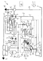
- FIG. 1 is a circuit diagram of a hydrostatic drive system 1 according to the invention and drive train of a vehicle, not shown, for example, designed as a truck or construction or agricultural machine mobile machine, shown in a schematic diagram.
- the drive system 1 comprises an internal combustion engine 2, for example a diesel engine, a traction drive 3 driven by the internal combustion engine 2 and a working hydraulic system 4 driven by the internal combustion engine 2.
- an internal combustion engine 2 for example a diesel engine
- a traction drive 3 driven by the internal combustion engine 2
- a working hydraulic system 4 driven by the internal combustion engine 2.
- the traction drive 3 is formed in the illustrated embodiment as a hydrostatic drive, which consists of a continuously variable in the delivery volume drive pump 5 as a primary unit, which is in drive connection to the drive with an output shaft 6 of the engine 2.
- the drive pump 5 is connected to one or more in the intake volume fixed or adjustable, not shown hydraulic motors as secondary units, in a closed circuit in combination, which are in a manner not shown in operative connection with the driven wheels of the vehicle.
- the traction drive 3 may alternatively be formed as an electric traction drive with a driven by the internal combustion engine 2 electric generator as the primary unit and one or more electric traction motors as secondary units.
- a mechanical traction drive with a mechanical transmission for example a stepped transmission or a power split transmission or a torque converter transmission can be provided as the drive.
- the working hydraulic system 4 includes working functions of the working machine, for example, in a truck, a working hydraulics for actuating a lifting device on a lifting mast, or in an example as an excavator or wheel loader-trained construction machine the working functions of working equipment trained by a shovel.
- the working hydraulic system 4 comprises to supply the working functions and thus the consumer with pressure means a hydrostatic engine 7.
- the engine 7 is operated in an open circuit and is for driving with the output shaft 6 of the engine 2 in drive connection.
- the engine 7 can be designed as constant-displacement engine in the displacement volume.
- the engine 7 is designed as an adjusting drive with a continuously variable displacement volume, for example as axial piston machine in swash plate design.
- the engine 7, which is operated in an open circuit, is connected on the inlet side to a suction connection by means of a suction line or a suction channel 8, which form a suction side S, with a container 9.
- An output side connected to the delivery port and the delivery side P of the engine 7 in connection conveyor line 10 is connected to a control valve device 11, by means of which the not shown hydraulic consumers of the working hydraulic system 4 are controllable.
- the control valve device 11 preferably comprises one or more directional control valves for actuating the consumers, which may also include a hydraulic steering device of the vehicle.
- the drive system 1 further comprises a feed pump 15, which is connected to the drive with the output shaft 6 in connection.
- the feed pump 15 is formed in the illustrated embodiment as a constant displacement pump with a constant displacement volume, which is operated in the open circuit.
- the feed pump 15 communicates with the suction side via a suction line 16 to the container 9 and conveys into a feed pressure line 17 connected to the feed ropes, to which the corresponding consumers of a feed pressure circuit 18 are connected, for example adjusting devices for adjusting the displacement volume of the drive pump 5 and 5 of the engine 7, a feeding device of the hydrostatic drive 3, a brake system of the vehicle and pilot valves for the control valves of the working hydraulic system 4.
- the feed pump 15 When the internal combustion engine 2, the feed pump 15 generates a constant feed pressure in the feed pressure circuit 18.
- a pressure limiting device such as a pressure relief valve assigned.
- the hydrostatic engine 7 of the working hydraulic system 4 is designed as Zwequadrantentriebwerk, which is operable at the same direction of rotation and the same flow direction of the pressure medium as a pump and motor.
- the engine 7 In pump operation, wherein the engine 7 is driven off by the running internal combustion engine 2, the engine 7 sucks pressure medium from the container 9 via the suction line 8 and delivers the pressure medium into the delivery line 10 for supplying the consumers of the working hydraulic system 4. Furthermore, the engine 7 is used in pump mode for loading a hydraulic accumulator 20 which can be connected via a charging valve 21 and a charging line 22 to the delivery line 10. For loading the accumulator 20 in this case the working in pump mode engine 7 can be driven either with the absorbed during deceleration of the vehicle kinetic energy of the vehicle or primary side of the current engine 2 driven.
- the engine 7 In engine operation of the engine 7, in which the engine 7 is designed as a hydraulic starter of a start-stop function for starting the engine 2, the engine 7 is driven on the suction side S with pressure medium from the accumulator 20.
- the connection of the accumulator 20 with the suction side S of the engine 7 for the engine operation of the engine 7 is controllable by means of an electrically actuated control valve 25.
- the control valve 25 has a blocking position 25a and a flow-through position 25b, wherein the blocking position 25a is preferably designed leakproof, with a blocking in the direction of the engine 7 check valve.
- the control valve 25 is designed as an electrically actuable control valve, preferably a switching valve, which can be actuated by means of an electrical actuating device 26, for example a solenoid, between the blocking position 25a and the flow position 25b.
- the actuating device 26 is connected to the control with an electronic control device 27 in connection.
- an electronic control device 27 For monitoring the accumulator charging pressure and thus the storage state of the pressure fluid accumulator 20, a pressure sensor device 28 connected to the control device 27 is provided.
- the electronic control device 27 is connected to a rotational speed sensor device 29 detecting the rotational speed of the internal combustion engine 2.
- the control device 27 can also control the charging valve 21 for the loading operation of the accumulator 20.
- the control valve 25 is arranged in a connecting line 23, which is guided by the accumulator 20 to the suction line 8 and connected to the suction line 8.
- a check valve device 30 is arranged between the connection of the connecting line 23 and the container 9, which allows a pressure build-up on the suction side S in engine operation of the engine 7.
- the check valve device 30 has an actuatable by means of an actuator 31 check valve 32.
- the check valve 32 is active between a in the FIG. 1 shown shut-off position 32a, in which the connection of the suction side S is shut off with the container 9 in the flow direction from the suction side S to the container 9, and one in the FIG. 1 shown in dashed lines open position 32b, in which the connection of the suction side S is open with the container 9.
- the engine 7 formed in the illustrated embodiment as an adjustment with a continuously variable displacement volume engine 7 has to adjust the displacer volume to a displacement volume adjusting device 40, for example, an inclination adjustable swash plate of an axial piston machine in swash plate design.
- the displacer volume adjusting device 40 comprises an actuating piston device 41 that is operatively connected to the displacer volume adjusting device 40 for actuation.
- the engine 7 according to the invention is designed as a unilaterally adjustable engine in which the displacer volume adjusting device 40 moves from a position with a minimum displacer volume in a setting direction or pivoting direction to a position Maximum displacer volume is adjustable.
- the actuating piston device 41 has an actuating pressure space 41 a acting in the direction of the maximum displacement volume and a control pressure space 41 b acting in the direction of the minimum displacement volume.
- the displacer volume adjusting device 40 can be actuated by means of an adjusting device 42.
- the adjusting device 42 has a control valve, not shown in detail, with which the loading of the control pressure chambers 41 a, 41 b of the control piston means 41 of the displacement volume adjusting device 40 with a control pressure or their discharge to the container 9 is controllable.
- the adjusting device 42 is connected to the supply pressure line 17 and thus the feed pressure circuit 18 for supplying pressure medium and for generating a setting pressure in the control pressure chambers 41 a and 41 b via a control pressure line 43. Furthermore, the adjusting device 42 has a connection to a container 9 guided to the container conduit 44. The adjusting device 42 is preferably electrically controllable and is for this purpose with the electronic control device 27 in connection. In the illustrated embodiment, the adjusting device 42 comprises a control valve, wherein a mechanical feedback and feedback 46 of the actual position of the displacement volume adjusting device 40 is provided on the adjusting device 42. Furthermore, a spring device 45 designed as a compression spring is provided, which acts on the displacement volume adjusting device 40 in the direction of the minimum displacement volume, which can be limited by a corresponding stop of the displacement volume adjusting device 40.
- the adjusting device 42 In order to pressurize the displacement volume adjusting device 40 in a start operation of the start-stop function of the parked internal combustion engine 2 by the engine operation of the engine 7 in the direction of the position with maximum displacement, the adjusting device 42 in addition to the supply of pressure medium and thus to generate a control pressure to the Pressure fluid accumulator 20 can be connected.
- a guided from the control pressure line 43 to the connecting line 23 pressure medium line 50 is provided.
- a pressure reducing valve 51 is arranged in the pressure medium line 50.
- the pressure medium line 50 is in this case connected between the control valve 25 and the suction line 8 to the connecting line 23.
- a check valve 52 is further arranged in the connection of the adjusting device 42 with the feed pressure circuit 18.
- the pressure medium line 50 is in this case connected between the check valve 52 and the adjusting device 42 to the control pressure line 43.
- the check valve 52 is formed in the illustrated embodiment as in the direction of the actuator 42 opening check valve 53.
- the inventive, arranged in the suction line 8 check valve 32 of the FIG. 1 is designed as a flap valve 33 with a pivotable about a pivot axis 35 flap 34.
- the flap 34 is operatively connected to the actuator 31 for operation.
- the actuator 31 of the check valve 32 is designed as a longitudinally displaceable actuating piston 36.
- the adjusting piston 36 has a piston rod 36 c, which is drivingly connected to the flap 34.
- the piston rod 36c of the actuating piston 36 with the intermediate position of a hinged to the flap 34 and hinged to the piston rod 36c of the actuating 36 articulated coupling rod 37, for example a rocker, with the flap 34 in operative connection.
- the adjusting piston 36 is arranged longitudinally displaceable in a cylinder housing, in which a control piston 36 in the direction of the illustrated shut-off 32a of the check valve 32 acting piston pressure chamber 36a and the adjusting piston 36 in the direction of the open position 32b of the check valve 32 acting piston pressure chamber 36b are formed.
- a control piston 36 in the direction of the illustrated shut-off 32a of the check valve 32 acting piston pressure chamber 36a and the adjusting piston 36 in the direction of the open position 32b of the check valve 32 acting piston pressure chamber 36b are formed in the piston pressure chamber 36a is arranged a control piston 36 and thus the check valve 32 in the shut-off position 32a acting spring means 38, for example a compression spring.
- the piston pressure chamber 36a provided with the spring device 38 is connected to the container 9 by means of a relief line 39.
- the non-return valve 32 can be actuated into the open position 32b by a hydraulic actuation pressure acting upon the actuation device 31.
- the actuating pressure of the constant feed pressure of the feed pressure circuit 18 is formed, including a branched off from the pressure medium line 50 and the control pressure line 43 branch line 60 to the acting in the opening direction piston pressure chamber 36b of the actuating piston 36th connected.
- a check valve 61 is arranged, which is formed in the illustrated embodiment as a blocking in the direction of the pressure reducing valve 51 check valve 62.
- the flap 34 of the flap valve 33 controls in the illustrated shut-off position 32a to a valve seat 65 which is formed in the suction line 8, which is formed for this purpose at least in the region of the valve seat 65 as a suction channel.
- the pivot axis 35 of the flap 34 is arranged in the radial direction outside the diameter D of the suction line 8, so that the flap 34 is not immersed in the open position 32b and thus the open switching position in the suction line 8 and in the open position 32b no additional hydraulic resistance and thus Flow resistance caused in the suction line 8.
- a radial extension 66 is formed on the suction line 8 designed as a suction channel into which the flap 34 preferably swings completely in the open position 32b.
- the check valve device 30 can be installed in the housing of the engine 7.
- the check valve device 30 has a separate housing 70, which forms a portion of the suction line 8.
- housing 70 of the check valve device 30 may further be the control valve 25 and the pressure reducing valve 51 are installed.
- the housing 70 can in this case preferably be flanged to the suction port of the engine 7 and thus grown. Alternatively, this housing 70 may be installed separately from the engine 7 at any point on the intake manifold 8 within the vehicle.
- the branch line 60 is the pressure generated at the pressure reducing valve 51 in the piston pressure chamber 36b of the actuating piston 36 and generates an acting in the direction of the open position of the flap 34 force on the control piston 36.
- the from the pressure of the accumulator 20 and thus the pressure in the suction line 8 force acting on the flap 34 in the direction of the shut-off position 32a outweighs the opening force on the adjusting piston 36, so that the flap 34 is held in the shut-off position 32a during the starting process of the internal combustion engine 2 and the engine operation of the engine 7.
- the engine 7 driven by the internal combustion engine 2 can be used to supply the load of the working hydraulic system 4 to the pump, wherein the flap 34 located in the open position 32b does not build up any additional hydraulic resistance in the suction line 8 and no flow resistances caused reduce the suction limit speed of the engine 7 in the pump mode.
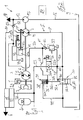
- FIG. 2 a second embodiment of the invention is shown.
- the same components are provided here with the same reference numerals.
- the FIG. 2 is different from the FIG. 1 with regard to the structural embodiment of the check valve 32 according to the invention.
- the check valve 32 of FIG. 2 is designed as a piston or flat slide valve 80 with a longitudinally displaceable piston or slide 81 which is operatively connected to the actuator 31 for actuation, which is analogous to the FIG. 1 is constructed.
- the piston or slide 81 can be actuated by means of the actuating device 31 by the actuating pressure formed as a feed pressure into the open position 32b and when the internal combustion engine 2 is switched off by means of the spring device 38 into the shut-off position 32a.
- the piston or slide 81 is arranged in the suction line 8 such that it does not form an additional flow resistance in the suction side S for the pressure medium drawn in by the engine 7 during pump operation in the open position 32b.
- the check valve 32 of the FIG. 2 be designed as a piston valve with a longitudinally displaceable and preferably cylindrical piston, which is operatively connected to the actuator 31 for actuation.
- the check valve may be formed as a ball valve.
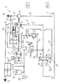
- FIG. 3 a third embodiment of the invention is shown.
- the same components are provided here with the same reference numerals.
- the check valve 32 is analogous to FIG. 2 designed as a piston or flat slide valve 80 with a longitudinally displaceable piston or slide 81, which is operatively connected to the actuator 31, which is designed as acting in the direction of the open position 32b control pressure surface 105 on the check valve 32.
- the control pressure surface 105 For acting on the control pressure surface 105 with the feed pressure formed as the actuating pressure, the control pressure surface 105 is connected to the branch line 60.
- the check valve 32 is acted upon by the spring device 38.
- the further control pressure surface 100 acting in the direction of the shut-off position 32a is provided on the check valve 32, which communicates with the control pressure line 101 to the check valve 32 at a starting operation of the internal combustion engine 2 of the pressure of the pressure medium accumulator 20 and thus the pressure in the suction line 8th to keep in the shut-off position 32a and to avoid that the check valve 32 is operated before the end of the starting process of the internal combustion engine 2 from the generated feed pressure against the force of the spring means 38 in the open position 32b.
- control valve 25 breaks in the control pressure line 43 and the pressure medium line 50 connected thereto feed pressure together, which acts on the control pressure surface 105, so that the check valve 32 of the spring device 38th is acted upon in the shut-off position 32a.
- the control valve 25 is actuated at pressure fluid reservoir 20 charged with pressure medium in the flow position 25b, so that when in the shut-off position 32a check valve 32, the engine 2 can be started by the engine operation of the engine 7.
- control valve 25 is actuated in the blocking position 25a, so that the pending on the further control pressure surface 100, acting in the closing direction pressure of the accumulator 20 collapses.
- the feed pressure generated by the driven feed pump 15 is applied via the branch line 60 to the scattering pressure surface 105, whereby the check valve 32 is actuated by means of the control pressure surface 105 formed as actuator 31 in the open position 32 b.
- FIGS. 1 and 2 is the spring-side, acting in the blocking position 32a piston pressure chamber 36a of the actuating piston 36 relieved via the discharge line 39 to the container and acting in the open position 32b piston pressure chamber 36b of the actuating piston 36 via the branch line 60 with the actuating pressure formed as a feed pressure acted upon by the Engine operation of the engine 7 to achieve a hydraulic starter for a start-stop function of the parked internal combustion engine 2.
- FIG. 4 is a further education of FIG. 1 represented, wherein the same components are provided with the same reference numerals.
- a switching valve 90 is provided, by means of which the check valve 32 in response to the actuation pressure in the open position 32b is actuated in a first switching position 90a and by means of which in a second switching position 90b, the check valve 32 in the shut-off position 32a operable is.
- the switching valve 90 is provided for controlling the loading of the piston pressure chambers 36a, 36b of the adjusting piston 36, by means of which in a first switching position 90a acting in opening position 32b piston pressure chamber 36b of the actuating piston 36 is acted upon by the actuating pressure and the spring side, acting in the blocking position 32a piston pressure chamber 36a is relieved to the container 9 and in a second switching position 90b of the spring-side, acting in the blocking position 32a piston pressure chamber 36a of the actuating piston 36 is acted upon by the actuating pressure and acting in the open position 32b piston pressure chamber 36b is relieved to the container 9.
- the switching valve 90 is for this purpose with the operating pressure leading branch line 60, the discharge line 39 and the two piston pressure chambers 36a, 36b of the Stellkobens 36 in conjunction.
- the switching valve 90 is designed as a four-port two-position valve.
- the switching valve 90 is designed as an electrically actuable control valve, preferably switching valve, which can be actuated by means of an electrical actuating device 91, for example a switching magnet, between the switching positions 90a, 90b.
- an electrical actuating device 91 for example a switching magnet
- To control the change-over valve 90 is in operative connection with the electronic control device 27.
- the switching valve 90 is preferably installed in the housing 70.
- the switching position 90b of the reversing valve 90 allows the reverse control of the check valve 32 to output by the engine operation of the hydrostatic engine 7 with the internal combustion engine 2, an additional torque to the output shaft 6 of the engine 2 and to achieve a booster drive.
- the engine 2 With the booster drive through the hydrostatic engine 7, the engine 2 can be supported, for example, while driving the vehicle.
- the changeover valve 90 is actuated into the switching position 90b, so that the feed pressure generated by the driven feed pump 15 during running internal combustion engine 2 via the control pressure line 43, the pressure medium line 50 and the branch line 60 in the spring-side, in the direction of the shut-off position 32a the check valve 32 acting piston pressure chamber 36a of the actuating piston 36 is present. Since in the switching position 90b of the switching valve 90 acting in the opening position 32b piston pressure chamber 36b of the actuating piston 36 is relieved to the container 9, the check valve 32 can be actuated in the shut-off position 32a to the connection of the suction line 8 in the flow direction to the container 9th shut off.
- the control valve 25 in the flow position 25b thus the engine 7 can be driven with pressurized pressure medium from the accumulator 20 during engine operation to feed a torque in the drive train to support the current internal combustion engine 2.
- FIG. 4 In the FIG. 4 is in the shut-off position 32a of the check valve 32, a connection of the suction side S with the container 9 in the direction of flow from the container 9 to the suction side S during the booster drive allows, including in a check valve 32 bypassing the bypass line 96 of the suction line S in the direction of the engine. 7 opening check valve 95 is provided.
- the check valve 95 makes it possible for the booster drive to suck in pressure medium of the engine 7 driven by the running internal combustion engine 2 from the container 9 in the shut-off position 32b located check valve 32 before opening the control valve 25 in the flow position 25b for the engine operation of the engine. 7
- FIG. 5 is a further education of FIG. 3 shown, with the by the switching valve 90, a booster drive through the hydrostatic engine 7 is made possible to support the current internal combustion engine 2.
- the switching valve 90 communicates with the operating pressure leading branch line 60, the control line 101 connected to the connecting line 23 and the two control pressure surfaces 100, 105 in combination.
- the switching valve 90 is designed as a four-port two-position valve and electrically actuated by means of the electrical actuator 91.
- the control pressure surface 105 of the check valve 32 is connected to the branch line 60 and thus acted upon by the actuating pressure.
- the further control pressure surface 100 of the check valve 32 is connected in the first switching position 90a to the control pressure line 101 and thus connected to the suction side S between the engine 7 and the check valve 32.
- the above-described operation of the check valve 32 results according to the FIG. 3 for the use of the engine 7 in engine operation as a hydraulic starter in the context of a start-stop function of the internal combustion engine. 2
- the control pressure surface 105 and the further control pressure surface 100 of the check valves 32 are connected to the branch line 60 and thus acted upon by the actuating pressure.
- the control pressure line 101 is shut off in the second switching position 90b of the switching valve 90.
- the switching valve 90 is actuated in the switching position 90b, in which the check valve 32 is actuated in the shut-off position 32a and the connection of the suction line 8 is shut off in the flow direction to the container 9.
- the switching valve 25 in the flow position 25b can thus the Engine 7 are driven with pressure fluid under pressure from the accumulator 20 in engine operation to feed a torque in the drive train to support the current internal combustion engine 2.
- FIG. 6 shows a further development of FIG. 3 that differ from the FIG. 5 differs by the execution of the switching valve 90.
- the switching valve 90 of FIG. 6 is designed as a five-port two-position valve, which is electrically actuated by means of the electrical actuator 91.
- the switching valve 90 communicates with the operating pressure leading branch line 60, the connected to the connecting line 23 control pressure line 101, the two control pressure surfaces 100, 105 and guided to the container 9 relief line 39 in connection.
- the control pressure surface 105 of the check valve 32 is connected to the branch line 60 and thus acted upon by the actuating pressure.
- the further control pressure surface 100 of the check valve 32 is connected in the first switching position 90a to the control pressure line 101 and thus connected to the suction side S between the engine 7 and the check valve 32.
- the discharge line 39 is shut off.
- the above-described operation of the check valve 32 results according to the FIG. 3 for the use of the engine 7 in engine operation as a hydraulic starter in the context of a start-stop function of the internal combustion engine. 2
- the control pressure surface 105 is connected to the relief line 39 and the other control pressure surface 100 connected to the branch line 60 and thus acted upon by the actuating pressure.
- the control pressure line 101 is shut off.
- the switching valve 90 is actuated in the switching position 90 b, in which the check valve 32 is actuated in the shut-off position 32 a and the Connection of the suction line 8 is shut off in the flow direction to the container 9.
- the switching valve 25 By driving the switching valve 25 in the flow position 25b thus the engine 7 can be driven with pressurized pressure fluid from the accumulator 20 in engine operation to feed a torque in the drive train to support the current internal combustion engine 2.
- Both Figures 5 and 6 is in the shut-off position 32a of the check valve 32, a connection of the suction side S with the container 9 in the direction of flow from the container 9 to the suction side S during the booster drive allows, for which purpose in the shut-off position 32a in the direction of the engine 7 opening check valve 95 is provided.
- the actuating device 31 which is in the form of a control piston or control surface 105, is acted upon by the pressure of the pressure medium reservoir 20 provided by the feed pump 15 as the feed pressure in the direction of the open position 32b of the check valve 32 that when the internal combustion engine 2, the check valve 32 is actuated in the open position 32 b.
- the check valve 32 is actuated by the spring means 38 in the shut-off position 32a and held by the spring device 38 in the shut-off position 32a.
- the check valve 32 When the internal combustion engine 2 is turned off, the check valve 32 is thus automatically in the shut-off position 32a, so that in a start-stop function by controlling the Control valve 25 in the flow position 25b directly and directly a hydrostatic start of the engine 2 by the engine operation of the engine 7 can be carried out without having to press the check valve 32 in the shut-off position 32a before.
- the function of the check valve 32 in a start-stop function and use of the engine 7 as a hydraulic starter of the internal combustion engine 2 can thus be achieved without additional control logic and additional control valves for controlling the actuator 31.
- the control of the check valve 32 are switched in the function to operate with the internal combustion engine 2 by operating the check valve 32 in the shut-off position 32a by running as a constant feed pressure operating pressure motor operation of the engine 7 for outputting a torque to the output shaft 6 for to create a booster drive.
- the check valve 32 may be formed as a spool valve with a rotatable piston or ball valve with a rotatable ball, wherein the piston or the ball with the actuator 31 is in operative connection and by means of the actuating piston 36 and as a control pressure surface 105 formed actuator 31 active between a shut-off and an open position is rotated.
- the hydrostatic engine 7 may alternatively be designed as an axial piston machine as a gear machine, as a radial piston machine or any other common construction, each with a constant displacement volume or alternatively continuously variable displacement volume.
- the invention is not limited to the illustrated sequence of the arrangement of the traction drive 3, the hydrostatic engine 7 and the feed pump 15 on the output shaft 6 of the internal combustion engine 2, but their arrangement can be varied and changed as desired.
Landscapes
- Engineering & Computer Science (AREA)
- Chemical & Material Sciences (AREA)
- Combustion & Propulsion (AREA)
- Mechanical Engineering (AREA)
- Transportation (AREA)
- General Engineering & Computer Science (AREA)
- Automation & Control Theory (AREA)
- Valve Device For Special Equipments (AREA)
- Fluid-Pressure Circuits (AREA)
- Applications Or Details Of Rotary Compressors (AREA)
Applications Claiming Priority (2)
| Application Number | Priority Date | Filing Date | Title |
|---|---|---|---|
| DE102013101796 | 2013-02-22 | ||
| DE201310101868 DE102013101868A1 (de) | 2013-02-22 | 2013-02-26 | Rückschlagventileinrichtung in der Saugseite eines bei gleicher Drehrichtung als Pumpe und Motor betreibbaren hydrostatischen Triebwerks |
Publications (2)
| Publication Number | Publication Date |
|---|---|
| EP2770192A2 true EP2770192A2 (fr) | 2014-08-27 |
| EP2770192A3 EP2770192A3 (fr) | 2016-07-13 |
Family
ID=50028841
Family Applications (1)
| Application Number | Title | Priority Date | Filing Date |
|---|---|---|---|
| EP14153079.0A Withdrawn EP2770192A3 (fr) | 2013-02-22 | 2014-01-29 | Dispositif de clapet anti-retour dans le côté aspiration d'une turbine hydrostatique pouvant fonctionner dans le même sens de rotation en tant que pompe et moteur |
Country Status (4)
| Country | Link |
|---|---|
| US (1) | US20140314587A1 (fr) |
| EP (1) | EP2770192A3 (fr) |
| CN (1) | CN104005895A (fr) |
| DE (1) | DE102013101868A1 (fr) |
Families Citing this family (2)
| Publication number | Priority date | Publication date | Assignee | Title |
|---|---|---|---|---|
| DE102014114138A1 (de) | 2014-09-29 | 2016-03-31 | Linde Material Handling Gmbh | Hydrostatisches Antriebssystem |
| RU180266U1 (ru) * | 2017-11-08 | 2018-06-07 | Акционерное общество "Сарапульский электрогенераторный завод" | Привод наземного транспортного средства на электротяге |
Citations (3)
| Publication number | Priority date | Publication date | Assignee | Title |
|---|---|---|---|---|
| EP2308795A1 (fr) | 2009-10-09 | 2011-04-13 | Linde Material Handling GmbH | Dispositif hydraulique et procédé de fonctionnement dans une machine de travail mobile |
| WO2012125798A1 (fr) | 2011-03-16 | 2012-09-20 | Parker Hannifin Corporation | Système de commande de démarrage utilisant une unique pompe hydraulique |
| DE102011105006A1 (de) | 2011-04-04 | 2012-10-04 | Linde Material Handling Gmbh | Antriebsstrang eines Fahrzeugs |
Family Cites Families (7)
| Publication number | Priority date | Publication date | Assignee | Title |
|---|---|---|---|---|
| US3116595A (en) * | 1961-05-22 | 1964-01-07 | New York Air Brake Co | Hydraulic starter system for engines |
| GB8429200D0 (en) * | 1984-11-19 | 1984-12-27 | Page R G | Check valve |
| US6957703B2 (en) * | 2001-11-30 | 2005-10-25 | Baker Hughes Incorporated | Closure mechanism with integrated actuator for subsurface valves |
| US6935114B2 (en) * | 2001-12-28 | 2005-08-30 | Caterpillar Inc | System and method for starting an engine |
| US20060108860A1 (en) * | 2004-11-23 | 2006-05-25 | Delaware Capital Formation | Brake energy recovery system |
| DE102006050873A1 (de) * | 2006-10-27 | 2008-04-30 | Robert Bosch Gmbh | Hydrostatischer Antrieb mit Bremsenergierückgewinnung |
| US9200648B2 (en) * | 2011-01-24 | 2015-12-01 | Purdue Research Foundation | Fluid control valve systems, fluid systems equipped therewith, and methods of using |
-
2013
- 2013-02-26 DE DE201310101868 patent/DE102013101868A1/de not_active Withdrawn
-
2014
- 2014-01-29 EP EP14153079.0A patent/EP2770192A3/fr not_active Withdrawn
- 2014-02-20 US US14/184,807 patent/US20140314587A1/en not_active Abandoned
- 2014-02-21 CN CN201410060261.2A patent/CN104005895A/zh active Pending
Patent Citations (3)
| Publication number | Priority date | Publication date | Assignee | Title |
|---|---|---|---|---|
| EP2308795A1 (fr) | 2009-10-09 | 2011-04-13 | Linde Material Handling GmbH | Dispositif hydraulique et procédé de fonctionnement dans une machine de travail mobile |
| WO2012125798A1 (fr) | 2011-03-16 | 2012-09-20 | Parker Hannifin Corporation | Système de commande de démarrage utilisant une unique pompe hydraulique |
| DE102011105006A1 (de) | 2011-04-04 | 2012-10-04 | Linde Material Handling Gmbh | Antriebsstrang eines Fahrzeugs |
Also Published As
| Publication number | Publication date |
|---|---|
| DE102013101868A1 (de) | 2014-08-28 |
| CN104005895A (zh) | 2014-08-27 |
| US20140314587A1 (en) | 2014-10-23 |
| EP2770192A3 (fr) | 2016-07-13 |
Similar Documents
| Publication | Publication Date | Title |
|---|---|---|
| EP2735657B1 (fr) | Chaîne cinématique d'un véhicule, notamment d'une machine de travail mobile | |
| EP2840252B1 (fr) | Moteur hydrostatique | |
| EP2735656B1 (fr) | Chaîne cinématique d'un véhicule | |
| DE102011104919A1 (de) | Antriebsstrang eines Fahrzeugs, insbesondere einer mobilen Arbeitsmaschine | |
| DE102011107061A1 (de) | Antriebsstrang eines Fahrzeugs, insbesondere einer mobilen Arbeitsmaschine | |
| DE112008000832T5 (de) | Hydrostatisches Antriebssystem mit einer variablen Ladungspumpe | |
| EP2735726B1 (fr) | Moteur hydrostatique pour le démarrage d'un moteur à combustion | |
| DE102010047628B4 (de) | Antriebsstrang einer mobilen Arbeitsmaschine | |
| DE102011105006A1 (de) | Antriebsstrang eines Fahrzeugs | |
| EP3095999B1 (fr) | Systeme d'entrainement hydrostatique | |
| DE102011104921A1 (de) | Antriebsstrang einer mobilen Arbeitsmaschine | |
| EP2770192A2 (fr) | Dispositif de clapet anti-retour dans le côté aspiration d'une turbine hydrostatique pouvant fonctionner dans le même sens de rotation en tant que pompe et moteur | |
| DE102012112381A1 (de) | Antriebsachse eines Fahrzeugs mit einer einen hydraulischen Druckmittelspeicher umfassenden Energierückgewinnungseinrichtung | |
| EP2735727B1 (fr) | Moteur hydrostatique en tant que démarreur hydraulique d'un moteur à combustion | |
| DE102014001369B4 (de) | Mobile hydraulische Baumaschine | |
| DE102014109152A1 (de) | Hydrostatisches Antriebssystem einer mobilen Arbeitsmaschine | |
| EP2962883B9 (fr) | Système d'entraînement hydrostatique | |
| DE102012109376A1 (de) | Schmierölsystem zur Versorgung von motorinternen Schmierstellen eines eine Hydraulikanlage, insbesondere eine Arbeitshydraulik, antreibenden Verbrennungsmotors mit Schmieröl | |
| EP3273057B1 (fr) | Unité à déplacement positif et système marche/arrêt hydraulique comprenant une telle unité à déplacement positif | |
| DE102009013340B4 (de) | Leistungsgeführter Konstantdruckregler | |
| DE102018207945A1 (de) | Mobile Arbeitsmaschine mit hydrostatischem Arbeits- und Fahrantrieb | |
| DE102009013341A1 (de) | Führung der Solldrehzahl eines Verbrennungsmotors | |
| DE102015119471A1 (de) | Hydrostatisches Antriebssystem | |
| EP2980005A1 (fr) | Systeme d'entrainement hydrostatique d'une machine de travail mobile, notamment d'un chariot de manutention | |
| DE102014110900A1 (de) | Hydrostatisches Antriebssystem einer mobilen Arbeitsmaschine |
Legal Events
| Date | Code | Title | Description |
|---|---|---|---|
| PUAI | Public reference made under article 153(3) epc to a published international application that has entered the european phase |
Free format text: ORIGINAL CODE: 0009012 |
|
| 17P | Request for examination filed |
Effective date: 20140129 |
|
| AK | Designated contracting states |
Kind code of ref document: A2 Designated state(s): AL AT BE BG CH CY CZ DE DK EE ES FI FR GB GR HR HU IE IS IT LI LT LU LV MC MK MT NL NO PL PT RO RS SE SI SK SM TR |
|
| AX | Request for extension of the european patent |
Extension state: BA ME |
|
| PUAL | Search report despatched |
Free format text: ORIGINAL CODE: 0009013 |
|
| AK | Designated contracting states |
Kind code of ref document: A3 Designated state(s): AL AT BE BG CH CY CZ DE DK EE ES FI FR GB GR HR HU IE IS IT LI LT LU LV MC MK MT NL NO PL PT RO RS SE SI SK SM TR |
|
| AX | Request for extension of the european patent |
Extension state: BA ME |
|
| RIC1 | Information provided on ipc code assigned before grant |
Ipc: B60K 6/12 20060101ALI20160607BHEP Ipc: B60W 30/18 20120101ALI20160607BHEP Ipc: B60W 10/06 20060101ALI20160607BHEP Ipc: F02B 73/00 20060101ALI20160607BHEP Ipc: F02N 7/00 20060101AFI20160607BHEP |
|
| STAA | Information on the status of an ep patent application or granted ep patent |
Free format text: STATUS: REQUEST FOR EXAMINATION WAS MADE |
|
| STAA | Information on the status of an ep patent application or granted ep patent |
Free format text: STATUS: THE APPLICATION IS DEEMED TO BE WITHDRAWN |
|
| 18D | Application deemed to be withdrawn |
Effective date: 20170114 |