EP2735682B1 - Curseur - Google Patents
Curseur Download PDFInfo
- Publication number
- EP2735682B1 EP2735682B1 EP13193484.6A EP13193484A EP2735682B1 EP 2735682 B1 EP2735682 B1 EP 2735682B1 EP 13193484 A EP13193484 A EP 13193484A EP 2735682 B1 EP2735682 B1 EP 2735682B1
- Authority
- EP
- European Patent Office
- Prior art keywords
- clamping plate
- window pane
- threaded sleeve
- screw
- pane
- Prior art date
- Legal status (The legal status is an assumption and is not a legal conclusion. Google has not performed a legal analysis and makes no representation as to the accuracy of the status listed.)
- Active
Links
Images



Classifications
-
- E—FIXED CONSTRUCTIONS
- E05—LOCKS; KEYS; WINDOW OR DOOR FITTINGS; SAFES
- E05F—DEVICES FOR MOVING WINGS INTO OPEN OR CLOSED POSITION; CHECKS FOR WINGS; WING FITTINGS NOT OTHERWISE PROVIDED FOR, CONCERNED WITH THE FUNCTIONING OF THE WING
- E05F11/00—Man-operated mechanisms for operating wings, including those which also operate the fastening
- E05F11/38—Man-operated mechanisms for operating wings, including those which also operate the fastening for sliding windows, e.g. vehicle windows, to be opened or closed by vertical movement
- E05F11/382—Man-operated mechanisms for operating wings, including those which also operate the fastening for sliding windows, e.g. vehicle windows, to be opened or closed by vertical movement for vehicle windows
- E05F11/385—Fixing of window glass to the carrier of the operating mechanism
Definitions
- the invention relates to a driver for guiding a window pane along a guide rail of a window regulator assembly.
- Such a driver is from the DE 10 2005 004 000 A1 known and enables a simplified subsequent adjustment of a window pane in the drivers of a window lifting device by enabling the window pane to be clamped without access to a screw inserted into the driver when the window pane is clamped.
- the driver consists of a driver base body and a flat receiving fork connected to the driver base body with two receiving legs and a screw for pulling the receiving legs together to clamp the window pane.
- a receiving leg has a number of openings near the axis of the screw through which a pressure piece with prismatic projections that can be actuated from the outside of the receiving leg extends and is displaceable in a direction parallel to the axis of the screw.
- a receiving leg facing away from the main driver body is provided with a A threaded sleeve is provided with a through-hole and an internal thread formed therein, into which the screw is screwed for bracing the receiving legs.
- the threaded sleeve has an external thread which is screwed into an internal thread of a knurled threaded nut resting on the outside of the pressure piece.
- the threaded nut is rotated to loosen the non-positive connection between the window pane and the driver, so that the pressure piece resting on the window pane moves away from the window pane.
- the contact pressure of the prismatic projections of the pressure piece on the window pane is reduced so that the window pane can be realigned.
- the threaded nut is tightened again against the pressure piece, thereby reestablishing the non-positive connection between the driver and the window pane.
- the object of the present invention is to provide a driver of the type mentioned at the outset, in which the window pane can be clamped both by means of the clamping screw and for readjustment by means of a screw element, for example in the form of a knurled wheel, with the driver with optimal surface pressure of the window pane, without that tensions occur in the clamping device.
- the solution according to the invention provides a driver for guiding a window pane along a guide rail of a window regulator assembly, in which the internal thread of the threaded sleeve with the clamping screw and the external thread of the The threaded sleeve is screwed to an internal thread of a screw element and the threaded sleeve is held axially (with respect to the clamping plate) displaceably and non-rotatably on the inner clamping plate and the screw element rests against the outside of the inner clamping plate of a clamping device clamping the window pane.
- the window pane is clamped between the two clamping plates in such a way that the clamping force is distributed over the entire contact area of the window pane with the clamping plates or a contact area predetermined by the shape of the clamping plates.
- the threaded sleeve held non-rotatably on the inner clamping plate enables the window pane to be clamped between the clamping plates independently of one another, on the one hand by the clamping screw and on the other hand by the screw element.
- tensions in the clamping device are prevented, since the inner clamping plate can move freely when the window pane is loosened and fixed by means of the screw element.
- the screw element is preferably designed in the form of a knurled wheel.
- the inner clamping plate around the bore receiving the threaded sleeve forms a bearing surface for the window pane with central force introduction, which is achieved by the arrangement of annular webs arranged concentrically to the bore of the inner and outer clamping plate, which protrude from the side facing the window pane of the inner and outer clamping plate , is amplified.
- the internal thread of the screw element is arranged in a passage.
- the tensioning screw is inserted through a passage of the inner clamping plate resting on the screw element, which, like the outer clamping plate, is preferably made of a plastic, so that contact of the window pane with the metallic clamping screw is prevented.
- the non-rotatable but axially displaceable mounting of the threaded sleeve in the inner clamping plate is preferably achieved via a form-fitting connection of the threaded sleeve with the inner clamping plate, so that the threaded sleeve can move axially within the form-fitting area.
- the form-fit area between the threaded sleeve and the inner clamping plate can consist, for example, of an end section of the threaded sleeve with a polygon which, when the window pane is installed, engages positively in a corresponding polygonal recess in the inner clamping plate, or of radial guide webs in the end section of the threaded sleeve that are mounted in the State of the window pane positively engage in radial guide grooves in the inner clamping plate.
- the polygon or the radial web in the end section of the threaded sleeve and the corresponding polygonal receptacle or the corresponding slot in the inner clamping plate have such an axial length that the form fit between the polygon or the radial web in the end section of the threaded sleeve and the corresponding polygonal receptacle or the The corresponding slot in the inner clamping plate is retained when the clamping plates are loosened.
- a clamping ring is arranged between the screw element and the inner clamping plate and is fitted onto the threaded sleeve.
- the window pane for example to align it with respect to the roof line of a motor vehicle in the case of a frameless window pane, there is a radial play between the outer diameter of the threaded sleeve or the passage of the inner clamping plate that accommodates the tensioning screw and the inner edge of the disk opening, in particular the inner edge of a disk hole, is provided by appropriate dimensioning of the disk opening and the clamping screw or the passage.
- the clamping plates have insertion bevels for receiving the lower edge of the window pane when the window pane is inserted into the gap between the clamping plates.
- the outer circumference of the screw element has a profiling in the manner of a toothing, which can be brought into engagement with the clamping device with a corresponding tool for releasing or producing the tensioning of the window pane.
- the lower ends of the clamping plates are suspended in a receptacle in the basic driver body, so that the clamping screw is inserted through a bore that is aligned with the bores of the clamping plates and with the screw head on the outside of the driver base body.
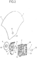
- a driver composed of a driver base body 2 and a clamping device 3 is provided, which is slidably arranged on a guide rail and adjustable along the guide rail by means of a pull rope from a window lifter drive.
- the main driver body 2 has an engagement area 20 for the guide rail and a nipple chamber 23 for receiving a nipple connected to the pull rope.
- the window pane 1 is connected to the driver by inserting the lower edge 12 of the pane into a slot-shaped opening between an inner clamping plate 4 and an outer clamping plate 5 of the clamping device 3 lying against the surface of the main driver body 2 facing the window pane 1, and by bracing the inner one Clamping plate 4 with the outer Clamping plate 5 is fixed.
- insertion bevels 40, 50 are provided on the upper edge of the inner and outer clamping plates 4, 5 which corresponds to that in the Figures 3 to 8
- the shown mounted state of the window pane 1 and the driver is inserted into a hook-shaped suspension 21 at the lower end of the driver base body 2.
- the clamping device 3 When the clamping device 3 is inserted into the hook-shaped suspension 21 of the driver base body 2, it is aligned according to the in Fig. 5 shown longitudinal section through the driver a bore 22 arranged in the driver base body 2 with bores 41, 51 in the clamping plates 4, 5 of the clamping device 3 and with the pane hole 10 of the window pane 1 inserted in the clamping device 3.
- the hexagon 91 corresponds to a hexagon socket 92 formed in an exposition or curvature 42 of the inner clamping plate 4 directed away from the outer clamping plate 5, so that the threaded sleeve 6 inserted into the inner clamping plate 4 in the assembled state is connected to the inner clamping plate 4 in a rotationally fixed manner.
- the threaded sleeve 6 has an internal thread 61 and an external thread 62.
- a clamping screw 7 is inserted through the bore 22 in the main driver body 2, the screw shaft 71 of which is provided with an external thread which is screwed to the internal thread 61 of the threaded sleeve 6.
- the screw head 70 resting on the outside of the main driver body 2 has according to FIG Fig. 2 a hexagon socket 72 for screwing the clamping screw 7 into the internal thread 61 of the threaded sleeve 6.
- the external thread 62 of the threaded sleeve 6 is screwed to an internal thread 81 of a screw element in the form of a knurled wheel 8, which rests against the outside of the inner clamping plate 4.
- the internal thread 81 of the knurled wheel 8 is arranged in a passage 82 directed away from the internal clamping plate 4, so that for screwing the external thread 62 of the threaded sleeve 6 with the internal thread 81 of the knurling wheel 8 a sufficient thread length is available.
- the outer edge of the knurling wheel 8 has knurling 80 designed in the manner of a toothing, into which a corresponding tool for operating the knurling wheel 8 can be inserted.
- the screw element 8 can be designed as a polygonal nut or as a washer with diagonal slots.
- a concentric bracing of the window pane 1 with the inner and outer clamping plates 4, 5 is supported by annular webs 43, 52 on the inner sides of the inner and outer clamping plates 4, 5 facing one another.
- the window pane 1 is connected to the driver as follows: Before connecting the window pane 1 to the driver, the threaded sleeve 6 is inserted into the bore 41 in the inner clamping plate 4 until the hexagon 91 of the inner clamping plate 4 is received by the hexagon socket 92 of the inner clamping plate 4.
- the internal thread 81 of the knurled wheel 8 is screwed onto the external thread 62 of the threaded sleeve 6 so that the external hexagon 91 of the threaded sleeve 6 is held in the internal hexagon 92 of the inner clamping plate 4 and the threaded sleeve 6 is rotatably mounted.
- the hexagon 91 of the threaded sleeve 6 in the assembled state is in engagement with the internal hexagon 92 formed in the curvature 42 of the inner clamping plate 4, the knurled wheel 8 almost completely with its internal thread 81 on the external thread 62 of the threaded sleeve 6 is screwed on.
- the window pane 1 is then inserted into the slot between the inner clamping plate 4 and the outer clamping plate 5 until the pane hole 10 is aligned with the aligned bores 22 of the driver base body 2, 51 of the outer clamping plate 5 and 41 of the inner clamping plate 4.
- the clamping screw 7 is inserted into the aligned bores 22, 41, 51 and the disk hole 10 aligned with the bores 22, 41, 51 and screwed to the internal thread 61 of the threaded sleeve 6 until the screw head 70 rests against the outside of the main driver body 2 and the window pane 1 is frictionally clamped between the mutually facing surfaces of the inner clamping plate 4 and the outer clamping plate 5.
- Fig. 5 shows that the passage 41 of the inner clamping plate 4 covers the shaft 71 of the clamping screw 7 radially, so that contact of the edge of the disk hole 10 with the metallic clamping screw 7 is avoided.
- Fig. 8 shown longitudinal section additionally also a positive connection between the pane hole 10 of the window pane 1 and the clamping screw 7 or the passage 41 of the inner clamping plate 4 surrounding the clamping screw 7 with sufficient radial play, which allows for tolerance compensation for adjusting or readjusting the window pane 1 with respect to the Door or vehicle body allows, so that, for example, the upper edge 11 of the window pane 1 can be adjusted in relation to the roof line of a vehicle door or vehicle body, in particular when using frameless window panes.
- the driver according to the invention makes it possible, in the manner described below, to adjust or readjust the window pane 1 without access to the clamping screw 7 after it has been installed.
- a tool is brought into engagement with the knurling 80 of the knurled wheel 8 and the knurled wheel 8 is brought into engagement with the knurled wheel 8 in the direction of loosening the knurled wheel 8 from its contact with the inner one Clamping plate 4 rotated.
- the knurled wheel 8 After aligning the window pane 1, the knurled wheel 8 is rotated in the opposite direction so that the knurled wheel 8 rests against the inner clamping plate 4 and thereby re-establishes the non-positive connection between the clamping device 3 of the driver and the window pane 1.
- the illustrated second embodiment for the non-rotatable mounting and axial displaceability of the threaded sleeve 6 differs from the one above on the basis of Figures 1 to 8 described embodiment only in the formation of the form-fitting connection of the end region of the threaded sleeve 6 with the arched or flared region 42 of the inner clamping plate 4, so that with respect to the other construction elements, their reference numerals with the reference numerals of the in the Figures 1 to 8 shown embodiment match, and their function reference is made to the preceding description.
- the positive connection of the end area of the threaded sleeve 6 with the arched or flared area 42 of the inner clamping plate 4 is established by radially aligned guide webs 93 formed in the end area of the threaded sleeve 6 and corresponding radial guide grooves 94 in the flared area 42 of the inner clamping plate 4 .
- a corresponding axial length of the guide grooves 94 in the exposed area 42 of the inner clamping plate 4 ensures that the threaded sleeve 6 has sufficient axial play in the guide grooves 94 when the knurled wheel 8 is released.
- a mounting clamping ring 15 is provided, which is arranged between the form-fit area of the threaded sleeve 6 and the knurled wheel 8.
- Fig. 10 illustrates in a perspective exploded view the passage 41 of the inner clamping plate 4 protruding into the clamping area of the window pane 1 with the clamping plates 4, 5 to protect the pane hole 10 of the window pane 1.
Landscapes
- Window Of Vehicle (AREA)
Claims (12)
- Entraîneur pour le guidage d'une vitre (1) le long d'un rail de guidage d'un ensemble lève-vitre, comportant un corps de base (2) de l'entraîneur et un dispositif de serrage (3) agencé sur le corps de base (2) de l'entraîneur et comportant une plaque de serrage intérieure (4) et une plaque de serrage extérieure (5) qui s'appuie sur le corps de base (2) de l'entraîneur, entre lesquelles la vitre (1) pourvue d'une percée de vitre (10) peut être serrée, et qui présentent des alésages (41, 51) alignés l'un avec l'autre et avec la percée de vitre (10) et à travers lesquels une douille filetée (6) et une vis de serrage (7) vissée à un filetage intérieur (61) de la douille filetée (6) sont insérées, un filetage extérieur de la douille filetée (6) étant vissé à un filetage intérieur d'un élément de vissage (8), et la douille filetée (6) étant maintenue de manière axialement déplaçable et solitaire en rotation sur la plaque de serrage intérieure (4), sur la face extérieure de laquelle l'élément de vissage (8) s'appuie pour serrer et desserrer le dispositif de serrage (3),dans lequel la plaque de serrage intérieure (4) forme une surface d'appui centrale pour la vitre (1) autour de son alésage (41) formé comme un soyage,dans lequel des nervures de support annulaires (43, 52) agencées concentriquement à l'alésage (41), formé comme un soyage, de la plaque de serrage intérieure (4) font saillie des plaques de serrage intérieure et extérieure (4, 5) depuis le côté tourné vers la vitre (1), etdans lequel la vis de serrage (7) est insérée à travers un alésage (22) du corps de base de l'entraîneur (2) qui est aligné avec le soyage (41) de la plaque de serrage intérieure (4) et de l'alésage (51) de la plaque de serrage extérieure (5) et s'appuie avec la tête de vis (70) contre le côté extérieur du corps de base (2) de l'entraîneur.
- Entraîneur au moins selon la revendication 1, caractérisé en ce que le filetage intérieur (81) de l'élément de vissage (8) est agencé dans un soyage (82) de l'élément de vissage (8).
- Entraîneur selon la revendication 1 ou 2, caractérisé en ce que l'alésage de la plaque de serrage intérieure (4) est formé comme un soyage (41) dirigé vers la plaque de serrage extérieure (5).
- Entraîneur selon au moins l'une quelconque des revendications précédentes, caractérisé en ce que la douille filetée (6) est reliée de manière non rotative à la plaque de serrage intérieure (4).
- Entraîneur selon la revendication 4, caractérisé en ce que la douille filetée (6) présente une partie d'extrémité avec un polygone (91) qui, à l'état monté de la vitre (1), vient en prise par complémentarité de forme dans un évidement polygonal (92), correspondant au polygone (91), dans la plaque de serrage intérieure (4).
- Entraîneur selon la revendication 4, caractérisé en ce que la douille filetée (6) présente une partie d'extrémité avec des nervures de guidage radiales (93) qui, à l'état monté de la vitre (1), vient en prise par complémentarité de forme dans des rainures de guidage radiales (94), correspondant aux nervures de guidage radiales (93), dans la plaque de serrage intérieure (4).
- Entraîneur selon la revendication 5 ou 6, caractérisé en ce que le polygone (91) ou les nervures de guidage radiales (93) dans la partie d'extrémité de la douille filetée (6) et le réceptacle polygonal correspondant (92) ou les rainures de guidage radiales (94) dans la plaque de serrage intérieure (4) présentent une telle longueur axiale, que la liaison de forme entre le polygone (91) ou les nervures de guidage radiales (93) dans la partie d'extrémité de la douille filetée (6) et le réceptacle polygonal correspondant (92) ou les rainures de guidage radiales (94) dans la plaque de serrage intérieure (4) est maintenu lorsque le serrage des plaques de serrages (4, 5) est desserré.
- Entraîneur selon au moins l'une quelconque des revendications précédentes, caractérisé en ce qu'une bague de serrage (15) est agencée entre l'élément de vissage (8) et la plaque de serrage intérieure (4).
- Entraîneur selon au moins l'une quelconque des revendications précédentes, caractérisé par un jeu radial entre la tige de vis (71) de la vis de serrage (7) ou le diamètre extérieur du soyage (41) de la plaque de serrage intérieure (4) et le bord intérieur de la percée de vitre (10).
- Entraîneur selon au moins l'une quelconque des revendications précédentes, caractérisé en ce que les plaques de serrage (4, 5) présentent des biseaux d'insertion (40, 50) pour recevoir le bord inférieur (12) de la vitre (1) lorsque la vitre (1) est insérée dans l'espace entre les plaques de serrage (4, 5).
- Entraîneur selon au moins l'une quelconque des revendications précédentes, caractérisé en ce que la circonférence extérieure de l'élément de vissage (8) présente un profilage à la manière d'une denture.
- Entraîneur selon au moins l'une quelconque des revendications précédentes, caractérisé en ce que les plaques de serrage (4, 5) sont suspendues par leurs extrémités inférieures dans une suspension en forme de crochet (21) du corps de base de l'entraîneur (2).
Applications Claiming Priority (1)
| Application Number | Priority Date | Filing Date | Title |
|---|---|---|---|
| DE202012104557.5U DE202012104557U1 (de) | 2012-11-23 | 2012-11-23 | Mitnehmer |
Publications (3)
| Publication Number | Publication Date |
|---|---|
| EP2735682A2 EP2735682A2 (fr) | 2014-05-28 |
| EP2735682A3 EP2735682A3 (fr) | 2017-09-06 |
| EP2735682B1 true EP2735682B1 (fr) | 2021-09-22 |
Family
ID=49596162
Family Applications (1)
| Application Number | Title | Priority Date | Filing Date |
|---|---|---|---|
| EP13193484.6A Active EP2735682B1 (fr) | 2012-11-23 | 2013-11-19 | Curseur |
Country Status (2)
| Country | Link |
|---|---|
| EP (1) | EP2735682B1 (fr) |
| DE (1) | DE202012104557U1 (fr) |
Families Citing this family (2)
| Publication number | Priority date | Publication date | Assignee | Title |
|---|---|---|---|---|
| IT201700110189A1 (it) * | 2017-10-02 | 2019-04-02 | Hi Lex Italy S P A | Dispositivo di regolazione della posizione del vetro di un alzacristallo di un autoveicolo. |
| DE102018200925A1 (de) | 2018-01-22 | 2019-07-25 | Brose Fahrzeugteile Gmbh & Co. Kommanditgesellschaft, Bamberg | Mitnehmer mit schwenkbarem Klemmteil und Montageverfahren |
Family Cites Families (2)
| Publication number | Priority date | Publication date | Assignee | Title |
|---|---|---|---|---|
| DE102005004000A1 (de) | 2005-01-27 | 2006-08-03 | Magna Closures (Germany) Gmbh | Mitnehmer |
| DE102005004546B4 (de) * | 2005-01-31 | 2008-01-10 | Küster Automotive Door Systems GmbH | Mitnehmer für einen Fensterheber |
-
2012
- 2012-11-23 DE DE202012104557.5U patent/DE202012104557U1/de not_active Expired - Lifetime
-
2013
- 2013-11-19 EP EP13193484.6A patent/EP2735682B1/fr active Active
Also Published As
| Publication number | Publication date |
|---|---|
| EP2735682A3 (fr) | 2017-09-06 |
| EP2735682A2 (fr) | 2014-05-28 |
| DE202012104557U1 (de) | 2014-02-27 |
Similar Documents
| Publication | Publication Date | Title |
|---|---|---|
| EP3698055B1 (fr) | Ensemble de compensation de tolérances | |
| EP2318723B1 (fr) | Agencement de fixation avec compensation des tolerances | |
| EP2720907B1 (fr) | Dispositif de fixation comprenant un compensateur de tolérance | |
| EP2130722B1 (fr) | Elément d'équilibrage de tolérance | |
| EP2532568B1 (fr) | Dispositif de fixation d'un composant, par exemple d'une rambarde, sur une carrosserie de véhicule | |
| EP2218924B1 (fr) | Dispositif de fixation destiné à l'agencement sur un rail de montage | |
| EP3036443B1 (fr) | Procédé pour assembler des pièces et module correspondant | |
| DE102012009173B4 (de) | Toleranzausgleichseinrichtung | |
| EP3586018B1 (fr) | Dispositif de fixation et module de fixation | |
| EP1201941A2 (fr) | Dispositif d'attachement pour rail | |
| EP1533185B1 (fr) | Elément de compensation de déviations de tolérance | |
| WO1998042480A1 (fr) | Element de vissage | |
| DE102016110754A1 (de) | Befestigungsvorrichtung zum Befestigen eines ersten Bauteils an einem zweiten Bauteil | |
| DE102005004000A1 (de) | Mitnehmer | |
| DE19755899C2 (de) | Antriebseinheit für Verstelleinrichtungen | |
| EP3132146B1 (fr) | Dispositif de fixation | |
| DE19912474C2 (de) | Befestigungsanordnung für die Anbringung eines Bauteils an einer C-förmigen Halteschiene | |
| EP2569550B1 (fr) | Moyen de fixation autobloquant et système de fixation | |
| DE102007014479B4 (de) | Spannvorrichtung | |
| EP2735682B1 (fr) | Curseur | |
| EP4095398B1 (fr) | Dispositif de compensation des tolérances entre deux composants à connecter | |
| DE19715496C1 (de) | Justierelement | |
| EP1612432B1 (fr) | Dispositif de fixation pour habillage et méthode de fixation | |
| EP3363969B1 (fr) | Poignée d'actionnement | |
| EP3120072B1 (fr) | Système de fixation de mât |
Legal Events
| Date | Code | Title | Description |
|---|---|---|---|
| PUAI | Public reference made under article 153(3) epc to a published international application that has entered the european phase |
Free format text: ORIGINAL CODE: 0009012 |
|
| 17P | Request for examination filed |
Effective date: 20131119 |
|
| AK | Designated contracting states |
Kind code of ref document: A2 Designated state(s): AL AT BE BG CH CY CZ DE DK EE ES FI FR GB GR HR HU IE IS IT LI LT LU LV MC MK MT NL NO PL PT RO RS SE SI SK SM TR |
|
| AX | Request for extension of the european patent |
Extension state: BA ME |
|
| RAP1 | Party data changed (applicant data changed or rights of an application transferred) |
Owner name: BROSE FAHRZEUGTEILE GMBH & CO. KOMMANDITGESELLSCHA |
|
| PUAL | Search report despatched |
Free format text: ORIGINAL CODE: 0009013 |
|
| AK | Designated contracting states |
Kind code of ref document: A3 Designated state(s): AL AT BE BG CH CY CZ DE DK EE ES FI FR GB GR HR HU IE IS IT LI LT LU LV MC MK MT NL NO PL PT RO RS SE SI SK SM TR |
|
| AX | Request for extension of the european patent |
Extension state: BA ME |
|
| RIC1 | Information provided on ipc code assigned before grant |
Ipc: E05F 11/38 20060101AFI20170731BHEP |
|
| STAA | Information on the status of an ep patent application or granted ep patent |
Free format text: STATUS: REQUEST FOR EXAMINATION WAS MADE |
|
| R17P | Request for examination filed (corrected) |
Effective date: 20180306 |
|
| RBV | Designated contracting states (corrected) |
Designated state(s): AL AT BE BG CH CY CZ DE DK EE ES FI FR GB GR HR HU IE IS IT LI LT LU LV MC MK MT NL NO PL PT RO RS SE SI SK SM TR |
|
| STAA | Information on the status of an ep patent application or granted ep patent |
Free format text: STATUS: EXAMINATION IS IN PROGRESS |
|
| 17Q | First examination report despatched |
Effective date: 20180706 |
|
| RAP1 | Party data changed (applicant data changed or rights of an application transferred) |
Owner name: BROSE FAHRZEUGTEILE SE & CO. KOMMANDITGESELLSCHAFT, BAMBERG |
|
| APBK | Appeal reference recorded |
Free format text: ORIGINAL CODE: EPIDOSNREFNE |
|
| APBN | Date of receipt of notice of appeal recorded |
Free format text: ORIGINAL CODE: EPIDOSNNOA2E |
|
| APBR | Date of receipt of statement of grounds of appeal recorded |
Free format text: ORIGINAL CODE: EPIDOSNNOA3E |
|
| APBV | Interlocutory revision of appeal recorded |
Free format text: ORIGINAL CODE: EPIDOSNIRAPE |
|
| GRAP | Despatch of communication of intention to grant a patent |
Free format text: ORIGINAL CODE: EPIDOSNIGR1 |
|
| STAA | Information on the status of an ep patent application or granted ep patent |
Free format text: STATUS: GRANT OF PATENT IS INTENDED |
|
| INTG | Intention to grant announced |
Effective date: 20210426 |
|
| GRAS | Grant fee paid |
Free format text: ORIGINAL CODE: EPIDOSNIGR3 |
|
| GRAA | (expected) grant |
Free format text: ORIGINAL CODE: 0009210 |
|
| STAA | Information on the status of an ep patent application or granted ep patent |
Free format text: STATUS: THE PATENT HAS BEEN GRANTED |
|
| AK | Designated contracting states |
Kind code of ref document: B1 Designated state(s): AL AT BE BG CH CY CZ DE DK EE ES FI FR GB GR HR HU IE IS IT LI LT LU LV MC MK MT NL NO PL PT RO RS SE SI SK SM TR |
|
| REG | Reference to a national code |
Ref country code: GB Ref legal event code: FG4D Free format text: NOT ENGLISH |
|
| REG | Reference to a national code |
Ref country code: DE Ref legal event code: R096 Ref document number: 502013015935 Country of ref document: DE |
|
| REG | Reference to a national code |
Ref country code: IE Ref legal event code: FG4D Free format text: LANGUAGE OF EP DOCUMENT: GERMAN |
|
| REG | Reference to a national code |
Ref country code: CH Ref legal event code: EP Ref country code: AT Ref legal event code: REF Ref document number: 1432455 Country of ref document: AT Kind code of ref document: T Effective date: 20211015 |
|
| REG | Reference to a national code |
Ref country code: SE Ref legal event code: TRGR |
|
| REG | Reference to a national code |
Ref country code: LT Ref legal event code: MG9D |
|
| REG | Reference to a national code |
Ref country code: NL Ref legal event code: MP Effective date: 20210922 |
|
| PG25 | Lapsed in a contracting state [announced via postgrant information from national office to epo] |
Ref country code: NO Free format text: LAPSE BECAUSE OF FAILURE TO SUBMIT A TRANSLATION OF THE DESCRIPTION OR TO PAY THE FEE WITHIN THE PRESCRIBED TIME-LIMIT Effective date: 20211222 Ref country code: RS Free format text: LAPSE BECAUSE OF FAILURE TO SUBMIT A TRANSLATION OF THE DESCRIPTION OR TO PAY THE FEE WITHIN THE PRESCRIBED TIME-LIMIT Effective date: 20210922 Ref country code: FI Free format text: LAPSE BECAUSE OF FAILURE TO SUBMIT A TRANSLATION OF THE DESCRIPTION OR TO PAY THE FEE WITHIN THE PRESCRIBED TIME-LIMIT Effective date: 20210922 Ref country code: LT Free format text: LAPSE BECAUSE OF FAILURE TO SUBMIT A TRANSLATION OF THE DESCRIPTION OR TO PAY THE FEE WITHIN THE PRESCRIBED TIME-LIMIT Effective date: 20210922 Ref country code: BG Free format text: LAPSE BECAUSE OF FAILURE TO SUBMIT A TRANSLATION OF THE DESCRIPTION OR TO PAY THE FEE WITHIN THE PRESCRIBED TIME-LIMIT Effective date: 20211222 Ref country code: HR Free format text: LAPSE BECAUSE OF FAILURE TO SUBMIT A TRANSLATION OF THE DESCRIPTION OR TO PAY THE FEE WITHIN THE PRESCRIBED TIME-LIMIT Effective date: 20210922 |
|
| PGFP | Annual fee paid to national office [announced via postgrant information from national office to epo] |
Ref country code: SE Payment date: 20211012 Year of fee payment: 9 Ref country code: FR Payment date: 20211109 Year of fee payment: 9 |
|
| PG25 | Lapsed in a contracting state [announced via postgrant information from national office to epo] |
Ref country code: LV Free format text: LAPSE BECAUSE OF FAILURE TO SUBMIT A TRANSLATION OF THE DESCRIPTION OR TO PAY THE FEE WITHIN THE PRESCRIBED TIME-LIMIT Effective date: 20210922 Ref country code: GR Free format text: LAPSE BECAUSE OF FAILURE TO SUBMIT A TRANSLATION OF THE DESCRIPTION OR TO PAY THE FEE WITHIN THE PRESCRIBED TIME-LIMIT Effective date: 20211223 |
|
| PG25 | Lapsed in a contracting state [announced via postgrant information from national office to epo] |
Ref country code: IS Free format text: LAPSE BECAUSE OF FAILURE TO SUBMIT A TRANSLATION OF THE DESCRIPTION OR TO PAY THE FEE WITHIN THE PRESCRIBED TIME-LIMIT Effective date: 20220122 Ref country code: SK Free format text: LAPSE BECAUSE OF FAILURE TO SUBMIT A TRANSLATION OF THE DESCRIPTION OR TO PAY THE FEE WITHIN THE PRESCRIBED TIME-LIMIT Effective date: 20210922 Ref country code: RO Free format text: LAPSE BECAUSE OF FAILURE TO SUBMIT A TRANSLATION OF THE DESCRIPTION OR TO PAY THE FEE WITHIN THE PRESCRIBED TIME-LIMIT Effective date: 20210922 Ref country code: PT Free format text: LAPSE BECAUSE OF FAILURE TO SUBMIT A TRANSLATION OF THE DESCRIPTION OR TO PAY THE FEE WITHIN THE PRESCRIBED TIME-LIMIT Effective date: 20220124 Ref country code: PL Free format text: LAPSE BECAUSE OF FAILURE TO SUBMIT A TRANSLATION OF THE DESCRIPTION OR TO PAY THE FEE WITHIN THE PRESCRIBED TIME-LIMIT Effective date: 20210922 Ref country code: NL Free format text: LAPSE BECAUSE OF FAILURE TO SUBMIT A TRANSLATION OF THE DESCRIPTION OR TO PAY THE FEE WITHIN THE PRESCRIBED TIME-LIMIT Effective date: 20210922 Ref country code: ES Free format text: LAPSE BECAUSE OF FAILURE TO SUBMIT A TRANSLATION OF THE DESCRIPTION OR TO PAY THE FEE WITHIN THE PRESCRIBED TIME-LIMIT Effective date: 20210922 Ref country code: EE Free format text: LAPSE BECAUSE OF FAILURE TO SUBMIT A TRANSLATION OF THE DESCRIPTION OR TO PAY THE FEE WITHIN THE PRESCRIBED TIME-LIMIT Effective date: 20210922 Ref country code: CZ Free format text: LAPSE BECAUSE OF FAILURE TO SUBMIT A TRANSLATION OF THE DESCRIPTION OR TO PAY THE FEE WITHIN THE PRESCRIBED TIME-LIMIT Effective date: 20210922 Ref country code: AL Free format text: LAPSE BECAUSE OF FAILURE TO SUBMIT A TRANSLATION OF THE DESCRIPTION OR TO PAY THE FEE WITHIN THE PRESCRIBED TIME-LIMIT Effective date: 20210922 |
|
| REG | Reference to a national code |
Ref country code: DE Ref legal event code: R097 Ref document number: 502013015935 Country of ref document: DE |
|
| PG25 | Lapsed in a contracting state [announced via postgrant information from national office to epo] |
Ref country code: MC Free format text: LAPSE BECAUSE OF FAILURE TO SUBMIT A TRANSLATION OF THE DESCRIPTION OR TO PAY THE FEE WITHIN THE PRESCRIBED TIME-LIMIT Effective date: 20210922 |
|
| REG | Reference to a national code |
Ref country code: CH Ref legal event code: PL |
|
| PG25 | Lapsed in a contracting state [announced via postgrant information from national office to epo] |
Ref country code: LU Free format text: LAPSE BECAUSE OF NON-PAYMENT OF DUE FEES Effective date: 20211119 Ref country code: DK Free format text: LAPSE BECAUSE OF FAILURE TO SUBMIT A TRANSLATION OF THE DESCRIPTION OR TO PAY THE FEE WITHIN THE PRESCRIBED TIME-LIMIT Effective date: 20210922 Ref country code: BE Free format text: LAPSE BECAUSE OF NON-PAYMENT OF DUE FEES Effective date: 20211130 |
|
| PLBE | No opposition filed within time limit |
Free format text: ORIGINAL CODE: 0009261 |
|
| STAA | Information on the status of an ep patent application or granted ep patent |
Free format text: STATUS: NO OPPOSITION FILED WITHIN TIME LIMIT |
|
| REG | Reference to a national code |
Ref country code: BE Ref legal event code: MM Effective date: 20211130 |
|
| 26N | No opposition filed |
Effective date: 20220623 |
|
| PG25 | Lapsed in a contracting state [announced via postgrant information from national office to epo] |
Ref country code: LI Free format text: LAPSE BECAUSE OF NON-PAYMENT OF DUE FEES Effective date: 20211130 Ref country code: CH Free format text: LAPSE BECAUSE OF NON-PAYMENT OF DUE FEES Effective date: 20211130 |
|
| PG25 | Lapsed in a contracting state [announced via postgrant information from national office to epo] |
Ref country code: IE Free format text: LAPSE BECAUSE OF NON-PAYMENT OF DUE FEES Effective date: 20211119 |
|
| PG25 | Lapsed in a contracting state [announced via postgrant information from national office to epo] |
Ref country code: SI Free format text: LAPSE BECAUSE OF FAILURE TO SUBMIT A TRANSLATION OF THE DESCRIPTION OR TO PAY THE FEE WITHIN THE PRESCRIBED TIME-LIMIT Effective date: 20210922 |
|
| REG | Reference to a national code |
Ref country code: AT Ref legal event code: MM01 Ref document number: 1432455 Country of ref document: AT Kind code of ref document: T Effective date: 20211119 |
|
| PG25 | Lapsed in a contracting state [announced via postgrant information from national office to epo] |
Ref country code: IT Free format text: LAPSE BECAUSE OF FAILURE TO SUBMIT A TRANSLATION OF THE DESCRIPTION OR TO PAY THE FEE WITHIN THE PRESCRIBED TIME-LIMIT Effective date: 20210922 Ref country code: AT Free format text: LAPSE BECAUSE OF NON-PAYMENT OF DUE FEES Effective date: 20211119 |
|
| PG25 | Lapsed in a contracting state [announced via postgrant information from national office to epo] |
Ref country code: HU Free format text: LAPSE BECAUSE OF FAILURE TO SUBMIT A TRANSLATION OF THE DESCRIPTION OR TO PAY THE FEE WITHIN THE PRESCRIBED TIME-LIMIT; INVALID AB INITIO Effective date: 20131119 |
|
| PG25 | Lapsed in a contracting state [announced via postgrant information from national office to epo] |
Ref country code: CY Free format text: LAPSE BECAUSE OF FAILURE TO SUBMIT A TRANSLATION OF THE DESCRIPTION OR TO PAY THE FEE WITHIN THE PRESCRIBED TIME-LIMIT Effective date: 20210922 |
|
| REG | Reference to a national code |
Ref country code: SE Ref legal event code: EUG |
|
| PG25 | Lapsed in a contracting state [announced via postgrant information from national office to epo] |
Ref country code: SM Free format text: LAPSE BECAUSE OF FAILURE TO SUBMIT A TRANSLATION OF THE DESCRIPTION OR TO PAY THE FEE WITHIN THE PRESCRIBED TIME-LIMIT Effective date: 20210922 |
|
| PG25 | Lapsed in a contracting state [announced via postgrant information from national office to epo] |
Ref country code: SE Free format text: LAPSE BECAUSE OF NON-PAYMENT OF DUE FEES Effective date: 20221120 |
|
| P01 | Opt-out of the competence of the unified patent court (upc) registered |
Effective date: 20230803 |
|
| PG25 | Lapsed in a contracting state [announced via postgrant information from national office to epo] |
Ref country code: FR Free format text: LAPSE BECAUSE OF NON-PAYMENT OF DUE FEES Effective date: 20221130 |
|
| PGFP | Annual fee paid to national office [announced via postgrant information from national office to epo] |
Ref country code: GB Payment date: 20231006 Year of fee payment: 11 |
|
| PG25 | Lapsed in a contracting state [announced via postgrant information from national office to epo] |
Ref country code: MK Free format text: LAPSE BECAUSE OF FAILURE TO SUBMIT A TRANSLATION OF THE DESCRIPTION OR TO PAY THE FEE WITHIN THE PRESCRIBED TIME-LIMIT Effective date: 20210922 |
|
| PG25 | Lapsed in a contracting state [announced via postgrant information from national office to epo] |
Ref country code: MT Free format text: LAPSE BECAUSE OF FAILURE TO SUBMIT A TRANSLATION OF THE DESCRIPTION OR TO PAY THE FEE WITHIN THE PRESCRIBED TIME-LIMIT Effective date: 20210922 |
|
| GBPC | Gb: european patent ceased through non-payment of renewal fee |
Effective date: 20241119 |
|
| PG25 | Lapsed in a contracting state [announced via postgrant information from national office to epo] |
Ref country code: GB Free format text: LAPSE BECAUSE OF NON-PAYMENT OF DUE FEES Effective date: 20241119 |
|
| PG25 | Lapsed in a contracting state [announced via postgrant information from national office to epo] |
Ref country code: TR Free format text: LAPSE BECAUSE OF FAILURE TO SUBMIT A TRANSLATION OF THE DESCRIPTION OR TO PAY THE FEE WITHIN THE PRESCRIBED TIME-LIMIT Effective date: 20210922 |
|
| PGFP | Annual fee paid to national office [announced via postgrant information from national office to epo] |
Ref country code: DE Payment date: 20251130 Year of fee payment: 13 |