EP2736100B1 - Unité électronique avec dispositif de mesure de la température pour un système de batterie - Google Patents
Unité électronique avec dispositif de mesure de la température pour un système de batterie Download PDFInfo
- Publication number
- EP2736100B1 EP2736100B1 EP12193807.0A EP12193807A EP2736100B1 EP 2736100 B1 EP2736100 B1 EP 2736100B1 EP 12193807 A EP12193807 A EP 12193807A EP 2736100 B1 EP2736100 B1 EP 2736100B1
- Authority
- EP
- European Patent Office
- Prior art keywords
- electronic unit
- measuring device
- temperature measuring
- battery
- temperature
- Prior art date
- Legal status (The legal status is an assumption and is not a legal conclusion. Google has not performed a legal analysis and makes no representation as to the accuracy of the status listed.)
- Active
Links
Images


Classifications
-
- G—PHYSICS
- G01—MEASURING; TESTING
- G01J—MEASUREMENT OF INTENSITY, VELOCITY, SPECTRAL CONTENT, POLARISATION, PHASE OR PULSE CHARACTERISTICS OF INFRARED, VISIBLE OR ULTRAVIOLET LIGHT; COLORIMETRY; RADIATION PYROMETRY
- G01J5/00—Radiation pyrometry, e.g. infrared or optical thermometry
- G01J5/02—Constructional details
- G01J5/028—Constructional details using a charging unit or battery
-
- H—ELECTRICITY
- H01—ELECTRIC ELEMENTS
- H01M—PROCESSES OR MEANS, e.g. BATTERIES, FOR THE DIRECT CONVERSION OF CHEMICAL ENERGY INTO ELECTRICAL ENERGY
- H01M10/00—Secondary cells; Manufacture thereof
- H01M10/42—Methods or arrangements for servicing or maintenance of secondary cells or secondary half-cells
- H01M10/48—Accumulators combined with arrangements for measuring, testing or indicating the condition of cells, e.g. the level or density of the electrolyte
- H01M10/482—Accumulators combined with arrangements for measuring, testing or indicating the condition of cells, e.g. the level or density of the electrolyte for several batteries or cells simultaneously or sequentially
-
- H—ELECTRICITY
- H01—ELECTRIC ELEMENTS
- H01M—PROCESSES OR MEANS, e.g. BATTERIES, FOR THE DIRECT CONVERSION OF CHEMICAL ENERGY INTO ELECTRICAL ENERGY
- H01M10/00—Secondary cells; Manufacture thereof
- H01M10/42—Methods or arrangements for servicing or maintenance of secondary cells or secondary half-cells
- H01M10/48—Accumulators combined with arrangements for measuring, testing or indicating the condition of cells, e.g. the level or density of the electrolyte
- H01M10/486—Accumulators combined with arrangements for measuring, testing or indicating the condition of cells, e.g. the level or density of the electrolyte for measuring temperature
-
- H—ELECTRICITY
- H01—ELECTRIC ELEMENTS
- H01M—PROCESSES OR MEANS, e.g. BATTERIES, FOR THE DIRECT CONVERSION OF CHEMICAL ENERGY INTO ELECTRICAL ENERGY
- H01M50/00—Constructional details or processes of manufacture of the non-active parts of electrochemical cells other than fuel cells, e.g. hybrid cells
- H01M50/50—Current conducting connections for cells or batteries
- H01M50/572—Means for preventing undesired use or discharge
- H01M50/574—Devices or arrangements for the interruption of current
- H01M50/581—Devices or arrangements for the interruption of current in response to temperature
-
- H—ELECTRICITY
- H01—ELECTRIC ELEMENTS
- H01M—PROCESSES OR MEANS, e.g. BATTERIES, FOR THE DIRECT CONVERSION OF CHEMICAL ENERGY INTO ELECTRICAL ENERGY
- H01M10/00—Secondary cells; Manufacture thereof
- H01M10/42—Methods or arrangements for servicing or maintenance of secondary cells or secondary half-cells
- H01M10/425—Structural combination with electronic components, e.g. electronic circuits integrated to the outside of the casing
- H01M2010/4271—Battery management systems including electronic circuits, e.g. control of current or voltage to keep battery in healthy state, cell balancing
-
- H—ELECTRICITY
- H01—ELECTRIC ELEMENTS
- H01M—PROCESSES OR MEANS, e.g. BATTERIES, FOR THE DIRECT CONVERSION OF CHEMICAL ENERGY INTO ELECTRICAL ENERGY
- H01M2200/00—Safety devices for primary or secondary batteries
- H01M2200/10—Temperature sensitive devices
-
- Y—GENERAL TAGGING OF NEW TECHNOLOGICAL DEVELOPMENTS; GENERAL TAGGING OF CROSS-SECTIONAL TECHNOLOGIES SPANNING OVER SEVERAL SECTIONS OF THE IPC; TECHNICAL SUBJECTS COVERED BY FORMER USPC CROSS-REFERENCE ART COLLECTIONS [XRACs] AND DIGESTS
- Y02—TECHNOLOGIES OR APPLICATIONS FOR MITIGATION OR ADAPTATION AGAINST CLIMATE CHANGE
- Y02E—REDUCTION OF GREENHOUSE GAS [GHG] EMISSIONS, RELATED TO ENERGY GENERATION, TRANSMISSION OR DISTRIBUTION
- Y02E60/00—Enabling technologies; Technologies with a potential or indirect contribution to GHG emissions mitigation
- Y02E60/10—Energy storage using batteries
Definitions
- the present invention relates to an electronic unit with temperature measuring device for a battery system.
- the invention further relates to a battery system comprising a plurality of battery cells and at least one electronic unit with a temperature measuring device.
- the temperature of the battery cells has a major influence on the performance, reliability and aging of a battery.
- By detecting the temperature of individual battery cells can be counteracted by means of cooling / heating means exceeding or falling below an upper and lower target limit of the temperature for the operation of the battery cells.
- diodes can be used as diodes.
- transistors which are connected as diodes.
- Most of the sensor elements are designed as NTC resistors or PTC resistors.
- the DE 10 2005 058 315 A1 discloses a measuring method that locally detects and determines the battery or battery surface at various spaced apart measuring points with an infrared sensor or a thermal imaging camera.
- different scanning paths or scan curves relative to the measuring battery or battery surface can be traversed with the infrared sensor, or it can be electronically selected from a thermal image recording individual measuring points according to a predetermined pattern.
- the more extensive the number of measuring points and the more complex the scanning paths or measuring point patterns the more accurate the statements about the temperature distribution and the more accurate statements on the battery or battery status become possible.
- the infrared sensor can be used in the DE 10 2005 058 315 A1
- the battery or battery surface can be scanned with a point-measuring infrared sensor by either the infrared sensor or the base of the battery measuring station is driven by a motor and thus movable, so that different scanning paths can be traversed by means of the motor.
- it may additionally be provided to pass through the measuring point grid several times with one scanning operation in order to better filter out statistical measured value deviations of a single measurement or at least to be able to compensate by averaging.
- the in the DE 10 2005 058 315 A1 described devices and the disclosed method are suitable for investigations on test benches and in laboratories.
- the reliable non-contact monitoring of the temperature of several battery cells of a battery module or a battery system is possible due to the installation position and the cramped space, for example in a motor vehicle in the manner described in the prior art only with great technical effort and high costs.
- thermocouples are contact-connected to the surface of the batteries.
- the EP 1 667 307 A1 describes a device for protection against excessive operating temperatures of mobile phones, the battery is mechanically coupled to a control system on a housing board in card form and an infrared thermal sensor with the battery is in non-contact measuring contact. It is therefore an object of the invention to improve temperature measuring devices of the type mentioned in this regard and in particular to provide a non-contact electronic unit with temperature measuring device that is easy to manufacture and permanently associated with a battery module of a battery system, and a continuous and reliable measurement of the temperature of multiple battery cells a battery system, in particular in a motor vehicle during operation allows.
- an electronic unit with temperature measuring device for a battery system wherein the battery system comprises a plurality of battery cells and at least one arranged in a battery housing of the battery system electronics unit with temperature measuring device, said on a circuit board of the electronic unit with temperature measuring device and the printed circuit board of the electronic unit with temperature measuring device operatively connected at least two infrared temperature sensors are arranged, wherein the infrared temperature sensors mechanically decoupled from the battery cells are arranged and aligned so that by an infrared temperature sensor, the temperature of a predetermined measuring range can be detected on a surface of the battery system, wherein an effective measuring field ( 35) is adjustable by the distance between the temperature sensors (32) and the monitored surface of the battery system.
- the predetermined measuring ranges are advantageously arranged at a distance from one another on the surface of the battery system such that they preferably do not overlap or overlap one another.
- the advantage of this electronic unit with temperature measuring device is that by using a plurality of infrared temperature sensors, the temperature of subregions of a battery system, in particular of individual battery cells and also of subregions of individual battery cells can be monitored simultaneously and continuously.
- the non-contact measurement of the surface temperature via infrared radiation enables the mechanical decoupling of the heavy battery cells from the sensitive sensor elements. Due to the precise and precise arrangement of the infrared temperature sensors, for example, on a printed circuit board of an electronic unit with temperature measuring device, a simple assembly of both the electronic unit and the battery system is given. In particular, the assembly and adjustment of the infrared temperature sensors having electronic unit with temperature measuring device on a multiple battery cell battery module is simplified compared to batteries with conventional temperature measuring devices.
- the battery module is a structural subunit of a battery system.
- a battery module comprises a plurality of mechanically and electrically interconnected battery cells and usually also an electronics unit and / or parts of a tempering system.
- a battery system typically includes multiple battery modules.
- the predetermined by the design of the infrared temperature sensor field of view of the sensor determines the orientation of the sensor and the distance to the measurement object, an "effective measuring field" on the surface of the measuring object, eg the battery cell of a battery system. At a correspondingly small distance, this "effective measuring field" is small enough to be able to detect subregions of a battery cell as predetermined measuring ranges.
- the measuring ranges are determined by suitable positioning and / or orientation of the infrared temperature sensors on or in the electronics unit with temperature measuring device predetermined.
- the object is also achieved by a battery system comprising a plurality of battery cells and at least one electronic unit with a temperature measuring device.
- the invention made possible by the detection of temperatures at selected portions of a plurality of battery cells allows better control of a tempering of the battery system and thus serves to increase the security against overheating of individual battery cells both when charging and while driving.
- the infrared temperature sensors used may include optical windows or other optical components, such as refractive or diffractive lenses.
- optical windows or other optical components such as refractive or diffractive lenses.
- additional optical components is preferably dispensed with.
- a distance of less than 50 millimeters between infrared temperature sensors and the respective predetermined measuring range on the surface of the battery system is suitable.
- this distance is less than 20 millimeters and more preferably less than 10 millimeters.
- the diameter of the "effective measuring field" may result, even without the use of additional optical components, a predetermined measuring range on a surface having a diameter of, for example, less than about 10 millimeters having.
- the infrared temperature sensors are arranged thermally decoupled from the printed circuit board of the electronic unit with temperature measuring device.
- Thermally decoupled in this patent is to be understood that measures are taken to reduce the heat transfer.
- the copper lamination of the printed circuit board in the vicinity of the infrared temperature sensor is largely removed and electrical lines (printed conductors) are designed with the smallest possible cross-section.
- electrical lines printed conductors
- a substantial exemption of the mounting range of the infrared temperature sensor on the circuit board by milling or punching is conducive.
- rapid temperature fluctuations of the infrared temperature sensors which are not caused by thermal radiation of the measurement objects (for example, caused by thermal conduction of heat sources on the circuit board of the electronics unit with temperature measuring device caused temperature fluctuations) or avoided.
- thermoelectric unit with a temperature measuring device in which the infrared temperature sensors are partially thermally decoupled from the surface of the battery cells by a first insulator arranged between the battery cells and a side facing the battery cells facing the electronic unit with temperature measuring device.
- the first insulator (one or more parts) is designed so that areas of the printed circuit board of the electronic unit with temperature measuring device in the immediate vicinity of the infrared temperature sensors protected against heat input.
- the active surface of the infrared temperature sensors is left out.
- the first insulator for example, openings.
- the openings in the first insulator are particularly preferably designed and arranged such that, on the one hand, they are as small as possible, but on the other hand, they do not impair the field of view and also the "effective measuring field" of the infrared temperature sensors.
- the first isolator prevents or reduces the transmission of rapid temperature fluctuations from other areas of the battery system, depending on the installation position in particular by convective heat transfer or by heat radiation, on portions of the temperature measuring device.
- the electronic unit with temperature measuring device is thermally decoupled from further components of the battery system by a second insulator arranged on the side of the electronics unit facing away from the battery cells with temperature measuring device.
- the first and second insulator can also be designed as a structural unit and thus enclose the entire electronic unit with temperature measuring device or parts thereof.
- the above-mentioned first and second insulators are thermal insulators. Suitable materials and further embodiments of said insulators, as well as further measures for the thermal decoupling of the infrared temperature sensors from their immediate surroundings, are known to the person skilled in the art.
- the electronic unit according to the invention with temperature measuring device in which the predetermined measuring range of the surface of the battery cell comprises a predetermined breaking point of the battery cell.
- the predetermined breaking point In the region of the predetermined breaking point, the wall of the battery cell on a smaller wall thickness, characterized in the case of malfunction of the battery cell, the surface of the battery cell is heated faster in the region of the predetermined breaking point and thus allows the early detection of errors.
- a predetermined measuring range of the surface of the battery cell is also located near a cell pole of the battery cell.
- a predetermined measuring range of the surface of the battery cell is also located near a cell pole of the battery cell.
- the predetermined measuring range lies on a cell connector arranged between two battery cells. This arrangement allows the simultaneous monitoring of two adjacent cell poles and thus battery cells with only one infrared temperature sensor.
- An arrangement in which the effective measuring field of an infrared temperature sensor simultaneously detects adjacent areas of the surfaces of two juxtaposed battery cells is advantageous and allows the simultaneous monitoring of two battery cells with only one infrared temperature sensor.
- the predetermined measuring range on a surface of the battery system has a means for increasing the emission coefficient. Should the surface of the predetermined Measuring range itself have no good emission properties (eg the smooth metallic surface of the cell connector) so the surface can be changed by applying a suitable layer (black matte paint, adhesive film, etc.) locally suitable.
- a suitable layer black matte paint, adhesive film, etc.
- At least one battery cell has a window in the region of the effective measuring field (35) of the infrared temperature sensor.
- Suitable materials for such a window are, for example, polypropylene and certain types of glass. Other suitable materials are known to the person skilled in the art.
- the infrared temperature sensor is a radiation thermopile or a bolometer. Both sensor types are particularly well suited for measuring low temperatures (-50 ° C to 100 ° C), can be made compact and can be easily installed on printed circuit boards.
- additional temperature sensors infrared temperature sensors and / or other types of temperature sensors
- additional temperature data for example, as reference data, from areas of the battery module or Battery system are detected, which are not accessible to the fixed on the PCB infrared temperature sensors.
- the electronic unit with temperature measuring device is a cell monitoring unit, wherein the cell monitoring unit measures the voltage at cell poles and / or cell connectors via voltage tapping elements.
- the electronic unit with temperature measuring device as cell monitoring unit usually houses a microprocessor which is set up for monitoring and usually also for regulating the cell voltages.
- the electronic unit with temperature measuring device is a connection board which can be connected to a cell monitoring unit.
- the interconnect board accommodates only the infrared temperature sensors and the required electrical leads which lead from the contacts of the infrared temperature sensors to a terminal for, for example, another electronic unit housing a microprocessor.
- the above-mentioned measures and devices according to the invention increase the operational safety of a battery system.
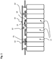
- a battery module comprising a number of battery cells 13 is shown.
- the cell poles 14 of adjacent battery cells 13 are interconnected by cell connectors 15 such that a series connection of the battery cells 13 results.
- An electronic unit 30 constructed on a printed circuit board has a number of infrared temperature sensors 32.
- the infrared temperature sensors 32 are arranged and aligned on the printed circuit board of the electronic unit 30 so that an effective measuring field 35 predetermined areas of the surface detected by battery cells.
- predetermined portions of the surface of each two adjacent battery cells are detected and monitored with only one infrared temperature sensor.
- the effective measuring field 35 of the infrared temperature sensors 32 is shown schematically in the side view as a cone. The opening angle of this field of view is determined by the design of the infrared temperature sensor and possibly contained therein optical devices. Given a field of view, the effective measuring field 35 can be adjusted by the distance between the temperature sensor and the surface to be monitored.
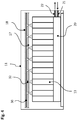
- FIG. 2 are the battery module and the electronic unit according to the invention with temperature measuring device Fig. 1 shown in plan view.
- the electronic unit 30 comprises, in addition to the three infrared temperature sensors 32 also shown, devices not shown for measuring the voltage levels of battery cells 13.
- the voltage levels of the battery cells 13 are conducted via voltage tapping elements 31 from the cell connectors 15 to the electronic unit 30.
- the effective measuring fields of the infrared temperature sensors 32 are circular and shown as broken lines.
- Each temperature sensor is assigned a signal conditioning unit which converts the measurement signal received by the temperature sensor into a measurement voltage or preferably into a digital measurement signal.
- the processed by the signal conditioning units measurement signals are fed to the evaluation of a microprocessor or microcontroller.
- FIG. 3 is a further exemplary embodiment of an electronic unit according to the invention with temperature measuring device shown.
- the illustrated electronic unit 30 has herein for each of the battery cells 13 has a separate infrared temperature sensor 32 assigned to it.
- FIG. 4 shows a battery system in a battery housing 11 with an arrangement for controlling the temperature of the battery cells 13.
- a temperature control 20 is supplied via an inlet opening 21 temperature control and returned via an outlet opening 22 in an external circuit for cooling / heating.
- the battery cells 13 are protected against overheating as well as against hypothermia.
- the tempering system 20 generates an optimal temperature range for operating the battery cells 13 in accordance with the measured data of the (infrared) temperature sensors.
- the electronic unit 30 together with infrared temperature sensors 32 is protected by a first insulator 17 and a second insulator 18 against thermal influences from other areas of the battery system.
- the first insulator 17 has small openings which are designed such that they do not impair the field of view and thus the effective measuring field 35 of the infrared temperature sensors 32.
- Microprocessors or microcontrollers are in the schematic representations of FIGS. 1 to 4 not shown. They can be arranged directly on the electronic units 30, or also be connected via analog and / or digital lines, in particular serial bus systems with higher-level electronic devices, for example a battery monitoring unit (BMU).
- BMU battery monitoring unit
Landscapes
- Chemical & Material Sciences (AREA)
- Chemical Kinetics & Catalysis (AREA)
- Electrochemistry (AREA)
- General Chemical & Material Sciences (AREA)
- Engineering & Computer Science (AREA)
- Manufacturing & Machinery (AREA)
- Physics & Mathematics (AREA)
- General Physics & Mathematics (AREA)
- Spectroscopy & Molecular Physics (AREA)
- Secondary Cells (AREA)
Claims (15)
- Unité électronique à dispositif de mesure de température (30) pour un système de batterie, le système de batterie comprenant plusieurs éléments de batterie (13) et au moins une unité électronique à dispositif de mesure de température (30) disposée dans un boîtier (11) du système de batterie,
caractérisée en ce que :au moins deux capteurs de température à infrarouge (32) sont disposés sur une carte de circuits imprimés de l'unité électronique à dispositif de mesure de température (30) et connectés à la carte de circuits imprimés de l'unité électronique à dispositif de mesure de température (30), les capteurs de température à infrarouge (32) étant disposés et alignés en étant mécaniquement désaccouplés des éléments de batterie (13) de manière à permettre la détection par chaque capteur de température à infrarouge (32) de la température d'une zone de mesure définie respective sur une surface du système de batterie, un champ de mesure (35) effectif étant réglable par espacement entre les capteurs de température (32) et la surface du système de batterie à surveiller. - Unité électronique à dispositif de mesure de température selon la revendication 1, caractérisée en ce que les capteurs de température à infrarouge (32) sont disposés en étant thermiquement désaccouplés de la carte de circuits imprimés de l'unité électronique à dispositif de mesure de température (30).
- Unité électronique à dispositif de mesure de température (30) selon la revendication 1 ou 2, caractérisée en ce que les capteurs de température à infrarouge (32) sont en partie thermiquement désaccouplés de la surface des éléments de batterie (13) par un premier isolant (17) disposé entre les éléments de batterie (13) et une face de l'unité électronique (30) opposée aux éléments de batterie.
- Unité électronique à dispositif de mesure de température (30) selon la revendication 3, caractérisée en ce que le premier isolant (17) présente des ouvertures au niveau des capteurs de température à infrarouge.
- Unité électronique à dispositif de mesure de température (30) selon l'une des revendications précédentes, l'unité électronique (30) étant caractérisée en ce qu'elle est thermiquement désaccouplée d'autres composants du système de batterie par un deuxième isolant (18) disposé sur la face de l'unité électronique (30) distante des éléments de batterie.
- Unité électronique à dispositif de mesure de température (30) selon l'une des revendications précédentes, caractérisée en ce que la zone de mesure définie de la surface de l'élément de batterie (13) comprend un point de cassure imposé de l'élément de batterie.
- Unité électronique à dispositif de mesure de température (30) selon l'une des revendications précédentes, caractérisée en ce que la zone de mesure définie de la surface de l'élément de batterie (13) est située à proximité d'un pôle de l'élément de batterie.
- Unité électronique à dispositif de mesure de température (30) selon l'une des revendications précédentes, caractérisée en ce que la zone de mesure définie est située sur un connecteur d'élément disposé entre deux éléments de batterie.
- Unité électronique à dispositif de mesure de température (30) selon l'une des revendications précédentes, caractérisée en ce que le champ de mesure (35) effectif d'un capteur de température à infrarouge (32) détecte simultanément deux éléments de batterie (13) situées côte à côte.
- Unité électronique à dispositif de mesure de température (30) selon l'une des revendications précédentes, caractérisée en ce que la zone de mesure définie présente un moyen d'élévation des coefficients d'émission sur une surface du système de batterie.
- Unité électronique à dispositif de mesure de température (30) selon l'une des revendications précédentes, caractérisée en ce qu'au moins un élément de batterie présente une fenêtre au niveau du champ de mesure (35) effectif du capteur de température à infrarouge (32).
- Unité électronique à dispositif de mesure de température (30) selon l'une des revendications précédentes, caractérisée en ce que le capteur de température à infrarouge est une thermopile à rayonnement ou un bolomètre.
- Unité électronique à dispositif de mesure de température (30) selon l'une des revendications précédentes, caractérisée en ce que des capteurs de température additionnels sont disposés sur la carte de circuits imprimés de l'unité électronique (30).
- Unité électronique à dispositif de mesure de température (30) selon l'une des revendications précédentes, l'unité électronique à dispositif de mesure de température (30) étant caractérisée en ce qu'elle est une unité de surveillance d'élément, l'unité de surveillance d'élément mesurant également la tension sur des pôles d'élément et/ou des connecteurs d'élément au moyen d'éléments de prélèvement de tension (31).
- Système de batterie comprenant plusieurs éléments de batterie (13) et au moins une unité électronique à dispositif de mesure de température (30) selon l'une des revendications précédentes.
Priority Applications (2)
| Application Number | Priority Date | Filing Date | Title |
|---|---|---|---|
| EP12193807.0A EP2736100B1 (fr) | 2012-11-22 | 2012-11-22 | Unité électronique avec dispositif de mesure de la température pour un système de batterie |
| US14/085,824 US9651428B2 (en) | 2012-11-22 | 2013-11-21 | Battery system temperature monitor |
Applications Claiming Priority (1)
| Application Number | Priority Date | Filing Date | Title |
|---|---|---|---|
| EP12193807.0A EP2736100B1 (fr) | 2012-11-22 | 2012-11-22 | Unité électronique avec dispositif de mesure de la température pour un système de batterie |
Publications (2)
| Publication Number | Publication Date |
|---|---|
| EP2736100A1 EP2736100A1 (fr) | 2014-05-28 |
| EP2736100B1 true EP2736100B1 (fr) | 2017-06-21 |
Family
ID=47355821
Family Applications (1)
| Application Number | Title | Priority Date | Filing Date |
|---|---|---|---|
| EP12193807.0A Active EP2736100B1 (fr) | 2012-11-22 | 2012-11-22 | Unité électronique avec dispositif de mesure de la température pour un système de batterie |
Country Status (2)
| Country | Link |
|---|---|
| US (1) | US9651428B2 (fr) |
| EP (1) | EP2736100B1 (fr) |
Cited By (2)
| Publication number | Priority date | Publication date | Assignee | Title |
|---|---|---|---|---|
| WO2021115979A1 (fr) | 2019-12-13 | 2021-06-17 | Viessmann Werke Gmbh & Co. Kg | Batterie ayant un dispositif de mesure de température |
| DE102022205218A1 (de) | 2022-05-25 | 2023-11-30 | Robert Bosch Gesellschaft mit beschränkter Haftung | Elektronische Baugruppe, insbesondere eine elektronische Leistungsbaugruppe für Hybridfahrzeuge oder Elektrofahrzeuge |
Families Citing this family (22)
| Publication number | Priority date | Publication date | Assignee | Title |
|---|---|---|---|---|
| JP6349731B2 (ja) * | 2014-01-08 | 2018-07-04 | 株式会社デンソー | 回路基板構造 |
| JP6108177B2 (ja) * | 2014-04-11 | 2017-04-05 | 株式会社オートネットワーク技術研究所 | 配線モジュール |
| US20160013523A1 (en) * | 2014-07-08 | 2016-01-14 | Robert Bosch Battery Systems Llc | Apparatus For Electrochemical Cell Temperature Measurement In A Battery Pack |
| CN104466298B (zh) * | 2014-11-20 | 2017-01-11 | 国家电网公司 | 动力电池的散热装置 |
| KR102705227B1 (ko) * | 2016-12-23 | 2024-09-10 | 삼성전자 주식회사 | 전자 장치 및 전자 장치의 충전 제어 방법 |
| US10393821B2 (en) * | 2017-03-29 | 2019-08-27 | Amazon Technologies, Inc. | Power supply monitoring system using optical estimation |
| KR102188723B1 (ko) | 2017-11-07 | 2020-12-08 | 주식회사 엘지화학 | 배터리 온도 추정 장치 및 방법 |
| DE102018118562A1 (de) * | 2018-07-31 | 2020-02-06 | Lisa Dräxlmaier GmbH | Batteriemodul und herstellverfahren |
| DE102019206365A1 (de) | 2019-05-03 | 2020-11-05 | Audi Ag | Verfahren zum frühzeitigen Detektieren einer bevorstehenden Überhitzung zumindest einer Batteriezelle einer Batterie, Detektionseinrichtung und Kraftfahrzeug |
| DE102019113065A1 (de) * | 2019-05-17 | 2020-11-19 | Bayerische Motoren Werke Aktiengesellschaft | Elektrischer akkumulator |
| US12033773B2 (en) * | 2019-06-03 | 2024-07-09 | Tdk Electronics Ag | Component and use of a component |
| JP7184720B2 (ja) * | 2019-09-09 | 2022-12-06 | トヨタ自動車株式会社 | 燃料電池セパレータ用部材の検査システムおよび検査方法 |
| DE102019126329A1 (de) * | 2019-09-30 | 2021-04-01 | Bayerische Motoren Werke Aktiengesellschaft | Batterie mit Lichtsensor sowie Kraftfahrzeug |
| CN111403836B (zh) * | 2020-03-26 | 2022-07-19 | 重庆金康赛力斯新能源汽车设计院有限公司 | 一种电池包温度检测系统以及方法 |
| KR102919683B1 (ko) * | 2020-05-25 | 2026-01-30 | 에스케이온 주식회사 | 배터리 모듈 및 배터리 팩 |
| CN112684738B (zh) * | 2020-12-14 | 2022-03-18 | 广州极飞科技股份有限公司 | 设备控制方法、装置及电池模块、非易失性存储介质 |
| JP7531423B2 (ja) * | 2021-02-19 | 2024-08-09 | 日立Astemo株式会社 | バッテリ用温度検出装置及びバッテリ |
| CN113029392B (zh) * | 2021-04-15 | 2024-05-31 | 高创(苏州)电子有限公司 | 一种体温测量方法、装置及电子设备 |
| IT202100012641A1 (it) * | 2021-05-17 | 2022-11-17 | Ferrari Spa | Unita' di controllo, pacco batteria veicolare e relativo metodo di assemblaggio |
| US12381266B2 (en) | 2022-07-21 | 2025-08-05 | GM Global Technology Operations LLC | Battery cell group temperature measurement system |
| WO2026077539A1 (fr) | 2024-10-10 | 2026-04-16 | Melexis Technologies Nv | Système de batterie de traction |
| CN120558400B (zh) * | 2025-05-28 | 2025-12-16 | 中山硕泰新能源技术有限公司 | 针床式化成分容柜的测温电路板、测温装置及测温系统 |
Family Cites Families (33)
| Publication number | Priority date | Publication date | Assignee | Title |
|---|---|---|---|---|
| JPH01307650A (ja) * | 1988-06-07 | 1989-12-12 | Hitachi Ltd | はんだ付け検査方法およびその装置 |
| JPH0361892A (ja) * | 1989-07-29 | 1991-03-18 | Toshiba Lighting & Technol Corp | 人体感知装置 |
| JPH04109832A (ja) * | 1990-08-28 | 1992-04-10 | Sony Corp | 2次電池用充電器 |
| US5483068A (en) * | 1994-01-07 | 1996-01-09 | Moulton; Russell D. | Use of IR (thermal) imaging for determining cell diagnostics |
| US5700089A (en) * | 1996-05-08 | 1997-12-23 | Ferret Instruments, Inc. | Battery tester with load temperature detection |
| FR2773214B1 (fr) * | 1996-12-11 | 2002-05-31 | Omega Engineering | Procede et dispositif pour la mesure par infrarouge de la temperature d'une surface |
| US6508584B2 (en) * | 1999-02-23 | 2003-01-21 | Intel Corporation | Method and apparatus for testing a temperature sensor |
| US6326766B1 (en) * | 2000-06-09 | 2001-12-04 | Shoot The Moon Products Ii, Llc | Rechargable battery pack and battery pack charger with safety mechanisms |
| US6469511B1 (en) * | 2001-07-18 | 2002-10-22 | Midtronics, Inc. | Battery clamp with embedded environment sensor |
| US6531847B1 (en) * | 2001-11-07 | 2003-03-11 | Quallion Llc | Safety method, device and system for an energy storage device |
| DE10214368B4 (de) * | 2002-03-30 | 2007-09-13 | Robert Bosch Gmbh | Energiespeichermodul und dessen Verwendung für ein Elektrogerät |
| US6919725B2 (en) * | 2003-10-03 | 2005-07-19 | Midtronics, Inc. | Electronic battery tester/charger with integrated battery cell temperature measurement device |
| US20050099163A1 (en) * | 2003-11-08 | 2005-05-12 | Andigilog, Inc. | Temperature manager |
| WO2005114811A2 (fr) * | 2004-05-17 | 2005-12-01 | Railpower Technologies Corp. | Agencement de bloc-batterie pour locomotive hybride |
| US7828478B2 (en) * | 2004-09-29 | 2010-11-09 | Delphi Technologies, Inc. | Apparatus and method for thermal detection |
| DE102004058435A1 (de) * | 2004-12-03 | 2006-06-14 | Liedtke, Rainer K., Dr. | Vorrichtungen zum Schutz gegen überhitzte Betriebstemperaturen von Mobiltelefonen |
| DE102005058315A1 (de) | 2005-12-07 | 2007-06-21 | Daimlerchrysler Ag | Verfahren zur exakten Erfassung und Bestimmung von Temperaturen in Batterien, Akkumulatoren oder Akku-Packs |
| KR20080053026A (ko) * | 2006-12-08 | 2008-06-12 | 엘지전자 주식회사 | 모바일기기의 입력키 |
| US20080272742A1 (en) * | 2007-05-01 | 2008-11-06 | William Stephen Hart | Method and apparatus for acquiring battery temperature measurements using stereographic or single sensor thermal imaging |
| JP4782072B2 (ja) * | 2007-05-18 | 2011-09-28 | パナソニック株式会社 | 電源装置 |
| US8754611B2 (en) * | 2008-04-11 | 2014-06-17 | Apple Inc. | Diffusion-limited adaptive battery charging |
| US8159341B2 (en) * | 2008-05-05 | 2012-04-17 | Thorad Corporation | Hazard detection and mitigation system and method |
| US8794827B2 (en) * | 2009-02-02 | 2014-08-05 | Yazaki Corporation | Thermal sensing structure and insulating structure of thermal sensing circuit |
| JP5248360B2 (ja) * | 2009-02-10 | 2013-07-31 | 矢崎総業株式会社 | 温度検出用回路体構造 |
| JP5640529B2 (ja) * | 2009-10-17 | 2014-12-17 | 三菱マテリアル株式会社 | 赤外線センサ及びこれを備えた回路基板 |
| US20110187377A1 (en) * | 2010-02-03 | 2011-08-04 | Dale Boysen | Battery Charger Tester With Individual Cell Temperature Measurement |
| WO2011146783A1 (fr) * | 2010-05-21 | 2011-11-24 | Qnovo Inc. | Procédé et circuit de charge adaptative d'un accumulateur/d'une cellule |
| US8410760B2 (en) * | 2010-08-02 | 2013-04-02 | GM Global Technology Operations LLC | Battery thermal system control strategy |
| JP5754626B2 (ja) * | 2011-03-30 | 2015-07-29 | 三菱マテリアル株式会社 | 赤外線センサ |
| US20130202009A1 (en) * | 2012-02-07 | 2013-08-08 | General Electric Company | Method and apparatus for displaying the temperature of an object |
| CN203323887U (zh) * | 2013-05-11 | 2013-12-04 | 深圳职业技术学院 | 一种动力电池组测温系统 |
| WO2015034844A1 (fr) * | 2013-09-03 | 2015-03-12 | Flir Systems, Inc. | Systèmes et procédés de détection de formation de glace sur base de l'infrarouge |
| US20160013523A1 (en) * | 2014-07-08 | 2016-01-14 | Robert Bosch Battery Systems Llc | Apparatus For Electrochemical Cell Temperature Measurement In A Battery Pack |
-
2012
- 2012-11-22 EP EP12193807.0A patent/EP2736100B1/fr active Active
-
2013
- 2013-11-21 US US14/085,824 patent/US9651428B2/en active Active
Non-Patent Citations (1)
| Title |
|---|
| None * |
Cited By (3)
| Publication number | Priority date | Publication date | Assignee | Title |
|---|---|---|---|---|
| WO2021115979A1 (fr) | 2019-12-13 | 2021-06-17 | Viessmann Werke Gmbh & Co. Kg | Batterie ayant un dispositif de mesure de température |
| US12506188B2 (en) | 2019-12-13 | 2025-12-23 | Viessmann Climate Solutions Se | Battery having a temperature measurement device |
| DE102022205218A1 (de) | 2022-05-25 | 2023-11-30 | Robert Bosch Gesellschaft mit beschränkter Haftung | Elektronische Baugruppe, insbesondere eine elektronische Leistungsbaugruppe für Hybridfahrzeuge oder Elektrofahrzeuge |
Also Published As
| Publication number | Publication date |
|---|---|
| US20140140369A1 (en) | 2014-05-22 |
| US9651428B2 (en) | 2017-05-16 |
| EP2736100A1 (fr) | 2014-05-28 |
Similar Documents
| Publication | Publication Date | Title |
|---|---|---|
| EP2736100B1 (fr) | Unité électronique avec dispositif de mesure de la température pour un système de batterie | |
| EP3178136B1 (fr) | Connecteur enfichable comprenant un dispositif de capteur de température | |
| DE10011233B4 (de) | Batterieeinheit | |
| DE102018200886B3 (de) | Verfahren zum Überwachen eines elektrischen Stromflusses | |
| EP1195275B1 (fr) | Dispositif pour évaluer la température dans l'habitacle d'un véhicule | |
| EP1457365B1 (fr) | Dispositif de détection de la température dans l'habitacle d'un véhicule | |
| DE102016220110A1 (de) | Temperaturüberwachtes Ladesystem zur Übertragung von elektrischen Ladeströmen | |
| DE102016107401A1 (de) | Steckvorrichtung mit Temperaturerfassung | |
| DE102015106251A1 (de) | Steckverbinderteil mit einer Temperaturüberwachungseinrichtung | |
| EP1989922A1 (fr) | Procédé et dispositif de reconaissance d'une sonde de température raccordé à une commande | |
| EP3994026A1 (fr) | Élément connecteur de charge à température surveillée | |
| DE102018009749B4 (de) | Elektrisches Kontaktelement für einen Steckverbinder, Steckverbinder und Verfahren zum Überwachen eines elektrischen Stromflusses | |
| DE102019125736B4 (de) | Kalibrieren einer Ladeeinrichtung eines Elektrofahrzeugs | |
| DE102016110458B4 (de) | Bedieneinrichtung für eine Klimaautomatik eines Kraftfahrzeugs, Klimaautomatik sowie Kraftfahrzeug | |
| EP1636055B1 (fr) | Module de base destine a plusieurs unites de capteurs | |
| DE102014101156B4 (de) | Vorrichtung zum Bestimmen eines Messwerts in einer elektrischen Anlage und Verfahren | |
| WO2020078834A1 (fr) | Procédé et capteur de batterie de détection d'incendie dans un véhicule, et véhicule | |
| DE202015106844U1 (de) | Stecker mit einem Fahrzeugladekabel eines Elektro- oder Hybridfahrzeuges | |
| DE102022124708B3 (de) | Leiterplatte zum Einbau in einen Ladesteckverbinder für ein Elektro- oder Hybridfahrzeug, Ladesteckverbinder mit einer solchen Leiterplatte und Anordnung aus einer solchen Leiterplatte und einer zweiten Leiterplatte | |
| DE102019219602A1 (de) | Temperaturmesseinrichtung | |
| DE102013220516A1 (de) | Messeinrichtung | |
| DE102022124719A1 (de) | Ladesteckverbinder für Elektro- und Hybridfahrzeuge | |
| DE19802045A1 (de) | Vorrichtung zur Erfassung der Temperatur eines insbesondere strömenden Mediums | |
| DE102022206014A1 (de) | Heizeinrichtung und Kraftfahrzeug mit einer solchen Heizeinrichtung | |
| DE102005011053A1 (de) | Sonnensensor in MID-Technik |
Legal Events
| Date | Code | Title | Description |
|---|---|---|---|
| PUAI | Public reference made under article 153(3) epc to a published international application that has entered the european phase |
Free format text: ORIGINAL CODE: 0009012 |
|
| 17P | Request for examination filed |
Effective date: 20121122 |
|
| AK | Designated contracting states |
Kind code of ref document: A1 Designated state(s): AL AT BE BG CH CY CZ DE DK EE ES FI FR GB GR HR HU IE IS IT LI LT LU LV MC MK MT NL NO PL PT RO RS SE SI SK SM TR |
|
| AX | Request for extension of the european patent |
Extension state: BA ME |
|
| R17P | Request for examination filed (corrected) |
Effective date: 20141022 |
|
| RBV | Designated contracting states (corrected) |
Designated state(s): AL AT BE BG CH CY CZ DE DK EE ES FI FR GB GR HR HU IE IS IT LI LT LU LV MC MK MT NL NO PL PT RO RS SE SI SK SM TR |
|
| RAP1 | Party data changed (applicant data changed or rights of an application transferred) |
Owner name: SAMSUNG SDI CO., LTD. |
|
| 17Q | First examination report despatched |
Effective date: 20151028 |
|
| GRAP | Despatch of communication of intention to grant a patent |
Free format text: ORIGINAL CODE: EPIDOSNIGR1 |
|
| STAA | Information on the status of an ep patent application or granted ep patent |
Free format text: STATUS: GRANT OF PATENT IS INTENDED |
|
| RIC1 | Information provided on ipc code assigned before grant |
Ipc: G01J 5/02 20060101ALI20170119BHEP Ipc: H01M 2/34 20060101AFI20170119BHEP Ipc: H01M 10/42 20060101ALI20170119BHEP Ipc: H01M 10/48 20060101ALI20170119BHEP |
|
| INTG | Intention to grant announced |
Effective date: 20170208 |
|
| GRAS | Grant fee paid |
Free format text: ORIGINAL CODE: EPIDOSNIGR3 |
|
| GRAA | (expected) grant |
Free format text: ORIGINAL CODE: 0009210 |
|
| STAA | Information on the status of an ep patent application or granted ep patent |
Free format text: STATUS: THE PATENT HAS BEEN GRANTED |
|
| AK | Designated contracting states |
Kind code of ref document: B1 Designated state(s): AL AT BE BG CH CY CZ DE DK EE ES FI FR GB GR HR HU IE IS IT LI LT LU LV MC MK MT NL NO PL PT RO RS SE SI SK SM TR |
|
| REG | Reference to a national code |
Ref country code: GB Ref legal event code: FG4D Free format text: NOT ENGLISH |
|
| REG | Reference to a national code |
Ref country code: CH Ref legal event code: EP |
|
| REG | Reference to a national code |
Ref country code: IE Ref legal event code: FG4D Free format text: LANGUAGE OF EP DOCUMENT: GERMAN |
|
| REG | Reference to a national code |
Ref country code: AT Ref legal event code: REF Ref document number: 903667 Country of ref document: AT Kind code of ref document: T Effective date: 20170715 |
|
| REG | Reference to a national code |
Ref country code: DE Ref legal event code: R096 Ref document number: 502012010583 Country of ref document: DE |
|
| REG | Reference to a national code |
Ref country code: NL Ref legal event code: MP Effective date: 20170621 |
|
| REG | Reference to a national code |
Ref country code: FR Ref legal event code: PLFP Year of fee payment: 6 |
|
| PG25 | Lapsed in a contracting state [announced via postgrant information from national office to epo] |
Ref country code: HR Free format text: LAPSE BECAUSE OF FAILURE TO SUBMIT A TRANSLATION OF THE DESCRIPTION OR TO PAY THE FEE WITHIN THE PRESCRIBED TIME-LIMIT Effective date: 20170621 Ref country code: GR Free format text: LAPSE BECAUSE OF FAILURE TO SUBMIT A TRANSLATION OF THE DESCRIPTION OR TO PAY THE FEE WITHIN THE PRESCRIBED TIME-LIMIT Effective date: 20170922 Ref country code: FI Free format text: LAPSE BECAUSE OF FAILURE TO SUBMIT A TRANSLATION OF THE DESCRIPTION OR TO PAY THE FEE WITHIN THE PRESCRIBED TIME-LIMIT Effective date: 20170621 Ref country code: LT Free format text: LAPSE BECAUSE OF FAILURE TO SUBMIT A TRANSLATION OF THE DESCRIPTION OR TO PAY THE FEE WITHIN THE PRESCRIBED TIME-LIMIT Effective date: 20170621 Ref country code: NO Free format text: LAPSE BECAUSE OF FAILURE TO SUBMIT A TRANSLATION OF THE DESCRIPTION OR TO PAY THE FEE WITHIN THE PRESCRIBED TIME-LIMIT Effective date: 20170921 |
|
| REG | Reference to a national code |
Ref country code: LT Ref legal event code: MG4D |
|
| PG25 | Lapsed in a contracting state [announced via postgrant information from national office to epo] |
Ref country code: NL Free format text: LAPSE BECAUSE OF FAILURE TO SUBMIT A TRANSLATION OF THE DESCRIPTION OR TO PAY THE FEE WITHIN THE PRESCRIBED TIME-LIMIT Effective date: 20170621 Ref country code: RS Free format text: LAPSE BECAUSE OF FAILURE TO SUBMIT A TRANSLATION OF THE DESCRIPTION OR TO PAY THE FEE WITHIN THE PRESCRIBED TIME-LIMIT Effective date: 20170621 Ref country code: SE Free format text: LAPSE BECAUSE OF FAILURE TO SUBMIT A TRANSLATION OF THE DESCRIPTION OR TO PAY THE FEE WITHIN THE PRESCRIBED TIME-LIMIT Effective date: 20170621 Ref country code: LV Free format text: LAPSE BECAUSE OF FAILURE TO SUBMIT A TRANSLATION OF THE DESCRIPTION OR TO PAY THE FEE WITHIN THE PRESCRIBED TIME-LIMIT Effective date: 20170621 Ref country code: BG Free format text: LAPSE BECAUSE OF FAILURE TO SUBMIT A TRANSLATION OF THE DESCRIPTION OR TO PAY THE FEE WITHIN THE PRESCRIBED TIME-LIMIT Effective date: 20170921 |
|
| PG25 | Lapsed in a contracting state [announced via postgrant information from national office to epo] |
Ref country code: EE Free format text: LAPSE BECAUSE OF FAILURE TO SUBMIT A TRANSLATION OF THE DESCRIPTION OR TO PAY THE FEE WITHIN THE PRESCRIBED TIME-LIMIT Effective date: 20170621 Ref country code: SK Free format text: LAPSE BECAUSE OF FAILURE TO SUBMIT A TRANSLATION OF THE DESCRIPTION OR TO PAY THE FEE WITHIN THE PRESCRIBED TIME-LIMIT Effective date: 20170621 Ref country code: RO Free format text: LAPSE BECAUSE OF FAILURE TO SUBMIT A TRANSLATION OF THE DESCRIPTION OR TO PAY THE FEE WITHIN THE PRESCRIBED TIME-LIMIT Effective date: 20170621 Ref country code: CZ Free format text: LAPSE BECAUSE OF FAILURE TO SUBMIT A TRANSLATION OF THE DESCRIPTION OR TO PAY THE FEE WITHIN THE PRESCRIBED TIME-LIMIT Effective date: 20170621 |
|
| PG25 | Lapsed in a contracting state [announced via postgrant information from national office to epo] |
Ref country code: IT Free format text: LAPSE BECAUSE OF FAILURE TO SUBMIT A TRANSLATION OF THE DESCRIPTION OR TO PAY THE FEE WITHIN THE PRESCRIBED TIME-LIMIT Effective date: 20170621 Ref country code: PL Free format text: LAPSE BECAUSE OF FAILURE TO SUBMIT A TRANSLATION OF THE DESCRIPTION OR TO PAY THE FEE WITHIN THE PRESCRIBED TIME-LIMIT Effective date: 20170621 Ref country code: SM Free format text: LAPSE BECAUSE OF FAILURE TO SUBMIT A TRANSLATION OF THE DESCRIPTION OR TO PAY THE FEE WITHIN THE PRESCRIBED TIME-LIMIT Effective date: 20170621 Ref country code: IS Free format text: LAPSE BECAUSE OF FAILURE TO SUBMIT A TRANSLATION OF THE DESCRIPTION OR TO PAY THE FEE WITHIN THE PRESCRIBED TIME-LIMIT Effective date: 20171021 Ref country code: ES Free format text: LAPSE BECAUSE OF FAILURE TO SUBMIT A TRANSLATION OF THE DESCRIPTION OR TO PAY THE FEE WITHIN THE PRESCRIBED TIME-LIMIT Effective date: 20170621 |
|
| REG | Reference to a national code |
Ref country code: DE Ref legal event code: R097 Ref document number: 502012010583 Country of ref document: DE |
|
| PLBE | No opposition filed within time limit |
Free format text: ORIGINAL CODE: 0009261 |
|
| STAA | Information on the status of an ep patent application or granted ep patent |
Free format text: STATUS: NO OPPOSITION FILED WITHIN TIME LIMIT |
|
| PG25 | Lapsed in a contracting state [announced via postgrant information from national office to epo] |
Ref country code: DK Free format text: LAPSE BECAUSE OF FAILURE TO SUBMIT A TRANSLATION OF THE DESCRIPTION OR TO PAY THE FEE WITHIN THE PRESCRIBED TIME-LIMIT Effective date: 20170621 |
|
| 26N | No opposition filed |
Effective date: 20180322 |
|
| PG25 | Lapsed in a contracting state [announced via postgrant information from national office to epo] |
Ref country code: MC Free format text: LAPSE BECAUSE OF FAILURE TO SUBMIT A TRANSLATION OF THE DESCRIPTION OR TO PAY THE FEE WITHIN THE PRESCRIBED TIME-LIMIT Effective date: 20170621 |
|
| PG25 | Lapsed in a contracting state [announced via postgrant information from national office to epo] |
Ref country code: CH Free format text: LAPSE BECAUSE OF NON-PAYMENT OF DUE FEES Effective date: 20171130 Ref country code: LI Free format text: LAPSE BECAUSE OF NON-PAYMENT OF DUE FEES Effective date: 20171130 |
|
| PG25 | Lapsed in a contracting state [announced via postgrant information from national office to epo] |
Ref country code: LU Free format text: LAPSE BECAUSE OF NON-PAYMENT OF DUE FEES Effective date: 20171122 Ref country code: SI Free format text: LAPSE BECAUSE OF FAILURE TO SUBMIT A TRANSLATION OF THE DESCRIPTION OR TO PAY THE FEE WITHIN THE PRESCRIBED TIME-LIMIT Effective date: 20170621 |
|
| REG | Reference to a national code |
Ref country code: BE Ref legal event code: MM Effective date: 20171130 |
|
| REG | Reference to a national code |
Ref country code: IE Ref legal event code: MM4A |
|
| PG25 | Lapsed in a contracting state [announced via postgrant information from national office to epo] |
Ref country code: MT Free format text: LAPSE BECAUSE OF FAILURE TO SUBMIT A TRANSLATION OF THE DESCRIPTION OR TO PAY THE FEE WITHIN THE PRESCRIBED TIME-LIMIT Effective date: 20170621 |
|
| REG | Reference to a national code |
Ref country code: FR Ref legal event code: PLFP Year of fee payment: 7 |
|
| PG25 | Lapsed in a contracting state [announced via postgrant information from national office to epo] |
Ref country code: IE Free format text: LAPSE BECAUSE OF NON-PAYMENT OF DUE FEES Effective date: 20171122 |
|
| PG25 | Lapsed in a contracting state [announced via postgrant information from national office to epo] |
Ref country code: BE Free format text: LAPSE BECAUSE OF NON-PAYMENT OF DUE FEES Effective date: 20171130 |
|
| PG25 | Lapsed in a contracting state [announced via postgrant information from national office to epo] |
Ref country code: HU Free format text: LAPSE BECAUSE OF FAILURE TO SUBMIT A TRANSLATION OF THE DESCRIPTION OR TO PAY THE FEE WITHIN THE PRESCRIBED TIME-LIMIT; INVALID AB INITIO Effective date: 20121122 |
|
| PG25 | Lapsed in a contracting state [announced via postgrant information from national office to epo] |
Ref country code: CY Free format text: LAPSE BECAUSE OF NON-PAYMENT OF DUE FEES Effective date: 20170621 |
|
| PG25 | Lapsed in a contracting state [announced via postgrant information from national office to epo] |
Ref country code: MK Free format text: LAPSE BECAUSE OF FAILURE TO SUBMIT A TRANSLATION OF THE DESCRIPTION OR TO PAY THE FEE WITHIN THE PRESCRIBED TIME-LIMIT Effective date: 20170621 |
|
| PG25 | Lapsed in a contracting state [announced via postgrant information from national office to epo] |
Ref country code: TR Free format text: LAPSE BECAUSE OF FAILURE TO SUBMIT A TRANSLATION OF THE DESCRIPTION OR TO PAY THE FEE WITHIN THE PRESCRIBED TIME-LIMIT Effective date: 20170621 |
|
| PG25 | Lapsed in a contracting state [announced via postgrant information from national office to epo] |
Ref country code: PT Free format text: LAPSE BECAUSE OF FAILURE TO SUBMIT A TRANSLATION OF THE DESCRIPTION OR TO PAY THE FEE WITHIN THE PRESCRIBED TIME-LIMIT Effective date: 20170621 |
|
| PG25 | Lapsed in a contracting state [announced via postgrant information from national office to epo] |
Ref country code: AL Free format text: LAPSE BECAUSE OF FAILURE TO SUBMIT A TRANSLATION OF THE DESCRIPTION OR TO PAY THE FEE WITHIN THE PRESCRIBED TIME-LIMIT Effective date: 20170621 |
|
| REG | Reference to a national code |
Ref country code: DE Ref legal event code: R079 Ref document number: 502012010583 Country of ref document: DE Free format text: PREVIOUS MAIN CLASS: H01M0002340000 Ipc: H01M0050572000 |
|
| P01 | Opt-out of the competence of the unified patent court (upc) registered |
Effective date: 20230528 |
|
| PGFP | Annual fee paid to national office [announced via postgrant information from national office to epo] |
Ref country code: DE Payment date: 20251104 Year of fee payment: 14 |
|
| PGFP | Annual fee paid to national office [announced via postgrant information from national office to epo] |
Ref country code: GB Payment date: 20251030 Year of fee payment: 14 |
|
| PGFP | Annual fee paid to national office [announced via postgrant information from national office to epo] |
Ref country code: AT Payment date: 20251110 Year of fee payment: 14 |
|
| PGFP | Annual fee paid to national office [announced via postgrant information from national office to epo] |
Ref country code: FR Payment date: 20251117 Year of fee payment: 14 |