EP2736833B1 - Steuervorrichtung - Google Patents
Steuervorrichtung Download PDFInfo
- Publication number
- EP2736833B1 EP2736833B1 EP12741251.8A EP12741251A EP2736833B1 EP 2736833 B1 EP2736833 B1 EP 2736833B1 EP 12741251 A EP12741251 A EP 12741251A EP 2736833 B1 EP2736833 B1 EP 2736833B1
- Authority
- EP
- European Patent Office
- Prior art keywords
- control device
- sensor
- movement speed
- load
- operating arm
- Prior art date
- Legal status (The legal status is an assumption and is not a legal conclusion. Google has not performed a legal analysis and makes no representation as to the accuracy of the status listed.)
- Not-in-force
Links
Images


Classifications
-
- E—FIXED CONSTRUCTIONS
- E02—HYDRAULIC ENGINEERING; FOUNDATIONS; SOIL SHIFTING
- E02F—DREDGING; SOIL-SHIFTING
- E02F9/00—Component parts of dredgers or soil-shifting machines, not restricted to one of the kinds covered by groups E02F3/00 - E02F7/00
- E02F9/26—Indicating devices
- E02F9/264—Sensors and their calibration for indicating the position of the work tool
- E02F9/265—Sensors and their calibration for indicating the position of the work tool with follow-up actions (e.g. control signals sent to actuate the work tool)
-
- B—PERFORMING OPERATIONS; TRANSPORTING
- B66—HOISTING; LIFTING; HAULING
- B66F—HOISTING, LIFTING, HAULING OR PUSHING, NOT OTHERWISE PROVIDED FOR, e.g. DEVICES WHICH APPLY A LIFTING OR PUSHING FORCE DIRECTLY TO THE SURFACE OF A LOAD
- B66F17/00—Safety devices, e.g. for limiting or indicating lifting force
- B66F17/003—Safety devices, e.g. for limiting or indicating lifting force for fork-lift trucks
-
- E—FIXED CONSTRUCTIONS
- E02—HYDRAULIC ENGINEERING; FOUNDATIONS; SOIL SHIFTING
- E02F—DREDGING; SOIL-SHIFTING
- E02F9/00—Component parts of dredgers or soil-shifting machines, not restricted to one of the kinds covered by groups E02F3/00 - E02F7/00
- E02F9/20—Drives; Control devices
- E02F9/2025—Particular purposes of control systems not otherwise provided for
- E02F9/2033—Limiting the movement of frames or implements, e.g. to avoid collision between implements and the cabin
Definitions
- the invention relates to a control device for preventing inadmissibly high tilting moments on a, equipped with at least one actuating device movable, in particular changeable in the insert working arm, mobile work machine.
- the DE 10 2009 018 072 A1 relates to a mobile work machine having a telescoping work arm pivotally hinged at one end thereof to the vehicle-type mobile work machine, and at its other opposite end the work arm comprises a movable work implement such as a forklift.
- An actuating kinematics is used to set and move both the working arm and the implement relative to the working machine.
- the work machine also has a central control unit, which coordinates the change in position of the working arm and implement and the movement of the work machine in the form of the vehicle and monitors and controls in cooperation with the central sensors.
- An acceleration sensor monitors the movement dynamics of the machine and the effect of gravity on the machine and limits and controls in cooperation with the central control unit, the accelerations.
- the GB 2 357 749 A describes a control device for preventing inadmissibly high tilting moments on a movable by an actuator, in particular extendable in the insert length, working arm equipped, mobile work machine, a support of rotatable in at least one direction working arm is associated with at least one driving part of the mobile machine, at least an angle sensor for determining at least one of the angular positions of the working arm relative to the driving part is provided, wherein an evaluation and control device with a computing unit for evaluating the signals of a cylinder length sensor, a chassis tilt sensor, a chassis tilt sensor and the respective angle sensor or to control the respective actuator is present , and wherein using the evaluation and control device, at least by processing the incoming signals of the chassis tilt sensor and the chassis tilt sensor, the Bewegu speed can be reduced.
- the inclination speed is reduced when at least one of the feet barely exerts force on the ground.
- the present invention seeks to provide a control device for preventing unacceptably high tilting moments on a mobile machine with a movable, in particular telescopic working arm, which is particularly reliable in a simple structure and the performance of the machine during operation of the same and the working arm substantially not affected.
- a bearing of the working arm rotatable in at least one direction is associated with at least one traveling part of the mobile working machine, that at least one load sensor for determining a bearing load on at least one of the driving parts and at least one angle sensor for determining at least one of the angular positions of the working arm relative to Driving part is provided that an evaluation and control device with a computing unit for evaluating the signals of the respective load sensor and the respective angle sensor or to control the respective actuator is present that using the evaluation and control device, at least by processing the incoming signals of the load sensor and the angle sensor, a maximum possible, each impermissible overturning moment preventing movement speed is determined for the moving working arm and that in such a way, the respective actuator so ans ans the working arm Experts that the determined maximum movement speed for each movement position of the working arm is not exceeded.
- a maximum possible movement speed for the movable working arm which prevents the respectively inadmissible tilting moment, is determined at least by processing the incoming signals of the load sensor and the angle sensor.
- the pertinent actuator controls the working arm so that the determined maximum speed of movement is not exceeded for each displacement position of the working arm.
- Control device that can constructively simple design, dynamic measurement errors are prevented, which could distort an erroneous determination of the highest possible movement speed, as would otherwise be possible by operational accelerations on the mobile machine.
- the speed of movement of the working arm of the mobile work machine is limited by the control device to a maximum possible extent, so that prevents unintentional tilting of the machine and to that extent the reliability is increased, while the working speed and extent the performance of the mobile machine is not affected.
- telelads To this end equipped with a working arm work machines are referred to technical terms as telelads.
- the maximum speed of movement for the movable working arm is calculated.
- the maximum movement speed can thus be calculated “online” by the computing unit (CPU) from the physical relationships.
- An alternative to this approach may be to include a so-called map in the considerations.
- a motion velocity characteristic field is stored in the arithmetic unit, preferably the arithmetic unit (CPU) of the control and working device, which can serve as a target specification for the maximum movement speed to be calculated.
- CPU arithmetic unit
- the application of a pertinent movement speed characteristic field makes it possible in a special way to quickly and reliably determine the respective possible maximum movement speed of the working arm.
- control device In an advantageous embodiment of the control device is provided that the calculation or determination of the maximum movement speed for the working arm estimating or determining the zu is preceded by moving load mass, which enters as an input in the calculation for the maximum movement speed. It is advantageous to use the incoming signals of the respective load sensor and of the respective angle sensor as well as of another sensor of the mobile working machine for determining a further operating parameter of the mobile working machine, such as a current load mass to be moved or a total mass with inclusion of the center of gravity.
- the application of the further sensor for determining at least one further operating parameter represents a further technical measure to make the calculation of the maximum possible speed of movement of the working arm precise. As a result, in turn, the overall working speed of the mobile machine is increased.
- a sensor can be used, which determines the current effective operating length of the working arm.
- the current effective length of use of the working arm which means in technical terms of the "load arm” - the current torque can be determined at the support of the working arm.
- the further sensor for determining the total mass with reference to the center of gravity position and to design it such that the sensor determines a further contact load on a further travel part of the mobile working machine.
- a pertinent embodiment of the control device is particularly preferably used in a mobile work machine whose respective travel part has at least one driving axis, on which the respectively assignable load sensor determines the bearing load.
- the actuating device for moving the working arm of the mobile working machine ie for changing the operating length and / or lifting height of the working arm
- the control device of at least one actuator preferably in the form of a hydraulic Working cylinder, formed.
- the hydraulic cylinder may be formed single or double acting, preferably for its control, the evaluation and control device is used, and the evaluation and control device is disposed within a, the hydraulic cylinder with hydraulic medium supplying hydraulic control circuit.
- control device can be used in any kind of mobile machines, but especially in mobile machines in the form of a loading crane, a telescopic loader, a wheel loader, an agricultural tractor or utility vehicle with front loader or rear loader, or with side loader, or in the manner of a construction machine, such as an excavator or shovel loader, or in the manner of a military vehicle, for example in the form of a recovery tank.
- a construction machine such as an excavator or shovel loader
- military vehicle for example in the form of a recovery tank.
- the respective driving part of the mobile machine can be constructed in different ways, in particular in the form of a wheelset, a chain or caterpillar drive or as a suspended magnetic part.
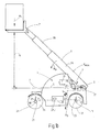
- FIGS. 1a and 1b is in a highly simplified functional sketch as a whole with 1 designated control device for preventing unacceptably high tilting moments M A at one, with one of at least one actuator 3 movable, especially in the insert length L variable working arm 5 equipped, mobile work machine 7 shown ,
- the mobile work machine 7 is formed in the manner of a telescopic loader.
- a support 9 of the rotatable in at least one direction working arm 5 is associated with a traveling part 11 of the mobile working machine 7.
- the working arm 5 is pivotally connected to the carriage 11 by means of the support 9 to the effect that the working arm 5 in the direction of the FIGS.
- the control device 1 comprises an evaluation and control device 17 with a computing unit CPU for evaluating the signals of the load sensor 13 and the angle sensor 15 and for determining the maximum movement speed V max .
- the evaluation and control unit 17 is also used to control the actuator 3.
- the control device 1 is under main or exclusive use of the evaluation and control device 17 by processing at least the incoming signals of the load sensor 13 and the angle sensor 15 determines a maximum possible, the respective impermissible tilting moment M A preventing movement speed V max for the moving working arm 5. It may also be advantageous to use a further control unit not shown in the figures for this purpose.
- the respective actuating device 3 then controls the working arm 5 so that the determined maximum movement speed V max is not exceeded for each displacement position of the working arm 5.
- a characteristic field is stored as a target specification for the calculated maximum movement speed V max .
- estimation or determination of the load mass m L to be moved can be preceded by using the evaluation and control unit 17, in particular using the arithmetic unit CPU, the load mass m L being the input variable in the calculation for the maximum movement speed V max is received.
- a further sensor 19 for determining at least one further operating parameter of the mobile work machine 7 is provided.
- the further sensor 19 is used in the in Fig. 1a shown embodiment for determining the current mass to be moved m L and is denoted by 20.
- the further sensor 19 is used with the aid of the evaluation and control unit 17 for determining the total mass m G of the mobile machine 7 and is denoted by 25.
- the sensor 25 in this case measures a further support load F 2 on a further travel part 21 of the mobile work machine.
- a center of gravity of the mobile work machine 7 with the help of the incoming signals of the respective load sensor 13 and the respective angle sensor 15 and the sensor 25 are determined.
- the sensor 20 is used to measure the current length of the working arm 5, which is telescopic, the pertinent current length is essentially the distance between the longitudinal axis 37 of the support 9 and a fictitious line of action m L L results, the in the illustration after the Fig. 1 passes through the designated with m L load arrow.
- the effective insertion length L is determined by the already described evaluation and control unit 17 together with the computing unit CPU according to the usual trigonometric functions, which, as shown in FIG Fig. 1a shown, again defined by the length between the longitudinal axis 37 of the support 9 and the already mentioned fictitious line of action.
- the mobile working machine 7 has two driving axles 23, 24, which form the respective driving parts 11, 21. At the driving axes 23, 24 determine the respective assignable sensors 13, 25, the respective support load F 1 , F 2 .
- the hydraulic cylinder 28 is arranged with its cylinder-side and piston rod side end hinged to the mobile machine 7 and the working arm 5.
- the respective working arms 5 are each formed of three mutually telescopic individual members 29, 30, 31.
- the evaluation and control unit 17 controls the actuator 27 by controlling components, such as valves, of a hydraulic control circuit 32 supplying the actuator 27 with hydraulic medium.
- the mobile work machine 7 can be configured manifold and instead of the telescopic handler shown in the form of a loading crane, a wheel loader, an agricultural utility or towing vehicle with front loader or with rear loader or side loader, or in the manner of a construction machine, or in the manner of a military vehicle, such as an armored recovery vehicle.
- the respective driving parts 11, 21, as shown, in the manner of a wheelset 33, 35 may be formed with arranged on each of the driving axle 23, 24 wheels.
- the respective driving parts as chain or caterpillar drive or as a wheelless magnetic suspended part, as is known in particular for industrial trucks, for transport purposes Production or assembly lines are used to train.
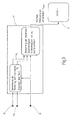
- Fig. 2 shows in the manner of a highly simplified flow chart, the function of the control device 1 in the in Fig. 1a shown embodiment.
- the evaluation and control unit 17 processes the sensor signals of the load sensor 13, the angle sensor 15 and the sensor 20, which are used in the embodiment shown, inter alia, for measuring the telescopic position of the working arm 5 formed as a telescopic arm.
- the evaluation and control unit 17 is able, with the aid of the sensor signals of the angle sensor 15 and the sensor 20, to calculate the effective insertion length L of the working arm 5.
- the signals of the load sensor 13 is of the evaluation and control unit 17, in particular of the computing unit CPU, the current load mass m L calculated.
- the evaluation and control unit 17 selects an associated, maximum movement speed V max for the working arm 5 from a movement speed characteristic field stored in the arithmetic unit CPU as a setpoint presetting. With the aid of the arithmetic unit CPU of the evaluation and control unit 17, the maximum movement speed V max for the working arm 5 can also be calculated without using the movement speed characteristic field.
- the maximum movement speed V max Due to the calculation method according to the invention of the maximum movement speed V max , on the one hand the possible total working speed of the mobile working machine 7 is limited to the most necessary measure and on the other hand, the coupling of dynamic measurement errors, as they are known for example in the use of acceleration sensors on such machines, completely prevented ,
- the calculated maximum movement speed V max thus represents a safe operating parameter for the mobile work machine 7 and its operation, which also limits the working speed of the mobile work machine 7 only to a necessary, the impermissible tilting moment M A preventing measure.
- Fig. 3 is also in the manner of a highly simplified flow chart, the function of the control device 1 in the mobile work machine 7, as in Fig. 1b shown is shown.
- the evaluation and control unit 17 of the control device 1 processes the sensor signals of the load sensor 13, the sensor 25 and the angle sensor 15 in the embodiment shown Total mass m G of the mobile work machine 7 to calculate. Furthermore, due to the measured load distribution at the two driving axes 23, 24 of the mobile working machine, the evaluation and control unit 17 able to calculate the current position of the center of gravity S of the mobile work machine 7. Even with the aid of the sensor signals of the load sensor 13 and the sensor 25, the arithmetic unit CPU can calculate the respective effective insertion length L of the working arm 5 via suitable algorithms, not shown in greater detail. Starting from the measured and calculated values, the evaluation and control unit 17 again selects the respective maximum possible movement speed V max of the working arm 5 from a movement speed characteristic field stored in the arithmetic unit CPU and controls the actuating device 3.
- Procedures for determining the respective maximum movement speed V max of the working arm 5 are influences of dynamic measurement errors that may be significant in the operation of many mobile machines prevented. Unlike in the case of known mobile machines, the operation is thus designed to be safe and, surprisingly, in comparison with the known mobile machines, a higher total operating speed of the mobile machine 7 is made possible, which increases their overall performance. The movement speed also indirectly influences the movement angle and thus prevents a static imbalance of the machines.
Landscapes
- Engineering & Computer Science (AREA)
- Structural Engineering (AREA)
- Mining & Mineral Resources (AREA)
- Civil Engineering (AREA)
- General Engineering & Computer Science (AREA)
- Life Sciences & Earth Sciences (AREA)
- Geology (AREA)
- Mechanical Engineering (AREA)
- Operation Control Of Excavators (AREA)
Description
- Die Erfindung betrifft eine Steuervorrichtung zum Verhindern unzulässig hoher Kippmomente an einer, mit einem, von mindestens einer Betätigungseinrichtung bewegbaren, insbesondere in der Einsatzlänge veränderbaren Arbeitsarm ausgestatteten, mobilen Arbeitsmaschine.
- Die
DE 10 2009 018 072 A1 betrifft eine mobile Arbeitsmaschine, die einen teleskopierbaren Arbeitsarm aufweist, der mit seinem einen Ende an der fahrzeugartigen mobilen Arbeitsmaschine schwenkbar angelenkt ist und an seinem anderen gegenüberliegenden Ende weist der Arbeitsarm ein bewegbares Arbeitsgerät, beispielsweise in der Art einer Lastgabel auf. Eine Betätigungskinematik dient dem Einstellen und Bewegen sowohl des Arbeitsarmes als auch des Arbeitsgerätes relativ zur Arbeitsmaschine. - Die Arbeitsmaschine weist ferner ein zentrales Steuergerät auf, das die Stellungsänderung von Arbeitsarm und Arbeitsgerät sowie die Bewegung der Arbeitsmaschine in Form des Fahrzeugs koordiniert und in Zusammenwirken mit den zentralen Sensoren überwacht und regelt. Ein Beschleunigungssensor überwacht dabei die Bewegungsdynamik der Arbeitsmaschine und die Wirkung der Erdbeschleunigung auf die Arbeitsmaschine und begrenzt und regelt dabei in Zusammenwirken mit dem zentralen Steuergerät die Beschleunigungen. Dergestalt ist eine zuverlässige Datenbereitstellung für die Zustandserkennung von fahrdynamischen Größen der mobilen Arbeitsmaschine in Bezug auf Geschwindigkeitsänderung, Querbeschleunigung und Fahrzeugneigung geschaffen, um dergestalt ein kippstabiles Arbeiten mit der mobilen Arbeitsmaschine nebst teleskopierbarem Arm sicherzustellen.
- Die
GB 2 357 749 A - Aus der
JP 2011-037565 A - Ausgehend von diesem Stand der Technik liegt der Erfindung die Aufgabe zugrunde, eine Steuervorrichtung zum Verhindern unzulässig hoher Kippmomente an einer mobilen Arbeitsmaschine mit bewegbarem, insbesondere teleskopierbarem Arbeitsarm zu schaffen, die bei einem einfachen Aufbau besonders betriebssicher ist und die Leistungsfähigkeit der Arbeitsmaschine beim Betrieb derselben sowie des Arbeitsarmes im Wesentlichen nicht beeinträchtigt.
- Diese Aufgabe wird mit einer Steuervorrichtung mit den Merkmalen des Anspruchs 1 in seiner Gesamtheit gelöst.
- Erfindungsgemäß ist vorgesehen, dass ein Auflager des in mindestens einer Richtung drehbaren Arbeitsarmes mindestens einem Fahrteil der mobilen Arbeitsmaschine zugeordnet ist, dass mindestens ein Lastsensor zur Bestimmung einer Auflagelast an zumindest einem der Fahrteile und mindestens ein Winkelsensor zur Bestimmung mindestens einer der Winkellagen des Arbeitsarmes relativ zum Fahrteil vorgesehen ist, dass ein Auswerte- und Steuergerät mit einer Recheneinheit zur Auswertung der Signale des jeweiligen Lastsensors und des jeweiligen Winkelsensors bzw. zur Ansteuerung der jeweiligen Betätigungseinrichtung vorhanden ist, dass unter Verwendung des Auswerte- und Steuergerätes zumindest durch Verarbeiten der eingehenden Signale des Lastsensors und des Winkelsensors eine maximal mögliche, das jeweils unzulässige Kippmoment verhindernde Bewegungsgeschwindigkeit für den bewegten Arbeitsarm ermittelt ist und dass dergestalt die jeweilige Betätigungseinrichtung derart den Arbeitsarm ansteuert, dass die ermittelte maximale Bewegungsgeschwindigkeit für jede Verfahrstellung des Arbeitsarmes nicht überschritten ist.
- Unter Verwendung des Auswerte- und Steuergeräts ist zumindest durch Verarbeiten der eingehenden Signale des Lastsensors und des Winkelsensors eine maximal mögliche, das jeweils unzulässige Kippmoment verhindernde Bewegungsgeschwindigkeit für den bewegbaren Arbeitsarm ermittelt.
- Die dahingehende Betätigungseinrichtung steuert den Arbeitsarm derart an, dass die ermittelte maximale Bewegungsgeschwindigkeit für jede Verfahrstellung des Arbeitsarmes nicht überschritten wird. Durch die erfindungsgemäße Steuervorrichtung, die konstruktiv einfach aufbauen kann, werden dynamische Messfehler verhindert, die eine fehlerhafte Bestimmung der größtmöglichen Bewegungsgeschwindigkeit verfälschen könnten, wie dies ansonsten durch betriebsbedingte Beschleunigungen an der mobilen Arbeitsmaschine möglich wäre. Die Bewegungsgeschwindigkeit des Arbeitsarms der mobilen Arbeitsmaschine wird von der Steuervorrichtung insoweit auf ein jeweils maximal mögliches Maß begrenzt, so dass ein ungewolltes Kippen der Arbeitsmaschine verhindert und insoweit die Betriebssicherheit erhöht ist, wobei gleichzeitig die Arbeitsgeschwindigkeit und insoweit die Leistungsfähigkeit der mobilen Arbeitsmaschine nicht beeinträchtigt wird. Dahingehend mit einem Arbeitsarm ausgestatte Arbeitsmaschinen werden fachsprachlich auch als Telelader bezeichnet.
- Mit Hilfe einer Recheneinheit, vorzugsweise der Recheneinheit (CPU) des Auswerte- und Steuergerätes, wird die maximale Bewegungsgeschwindigkeit für den bewegbaren Arbeitsarm berechnet. Die maximale Bewegungsgeschwindigkeit kann insoweit also "online" durch die Recheneinheit (CPU) aus den physikalischen Zusammenhängen berechnet werden.
- Eine Alternative zu diesem Lösungsansatz kann darin bestehen, ein sogenanntes Kennfeld in die Überlegungen mit einzubeziehen. Hierzu ist in der Recheneinheit, vorzugsweise der Recheneinheit (CPU) des Steuer- und Arbeitsgerätes ein Bewegungsgeschwindigkeits-Kennlinienfeld abgelegt, welches als Soll-Vorgabe für die zu berechnende maximale Bewegungsgeschwindigkeit dienen kann. Die Anwendung eines dahingehenden Bewegungsgeschwindigkeits-Kennlinienfeldes ermöglicht in besonderer Weise ein rasches und sicheres Bestimmen der jeweiligen möglichen maximalen Bewegungsgeschwindigkeit des Arbeitsarmes.
- In einem vorteilhaften Ausführungsbeispiel der Steuervorrichtung ist vorgesehen, dass der Berechnung oder Ermittlung der maximalen Bewegungsgeschwindigkeit für den Arbeitsarm ein Schätzen oder ein Ermitteln der zu bewegenden Lastmasse vorgeschaltet ist, die als Eingangsgröße in die Berechnung für die maximale Bewegungsgeschwindigkeit eingeht. Es ist vorteilhaft, für das Ermitteln eines weiteren Betriebsparameters der mobilen Arbeitsmaschine, wie eine aktuelle zu bewegende Lastmasse oder eine Gesamtmasse unter Einbezug der Schwerpunktlage, die eingehenden Signale des jeweiligen Lastsensors und des jeweiligen Winkelsensors sowie eines weiteren Sensors der mobilen Arbeitsmaschine heranzuziehen.
- Die Anwendung des weiteren Sensors zur Ermittlung zumindest eines weiteren Betriebsparameters stellt eine weitere technische Maßnahme dar, die Berechnung der maximal möglichen Bewegungsgeschwindigkeit des Arbeitsarmes präzise zu gestalten. Dadurch wiederum ist insgesamt die Arbeitsgeschwindigkeit der mobilen Arbeitsmaschine gesteigert.
- Als weiterer Sensor zur Ermittlung zumindest eines weiteren Betriebsparameters kann ein Sensor herangezogen werden, der die aktuelle wirksame Einsatzlänge des Arbeitsarmes ermittelt. Über die Kenntnis der aktuellen wirksamen Einsatzlänge des Arbeitsarmes - gemeint ist hier fachsprachlich der "Lastarm" - kann das jeweils aktuelle Drehmoment an dem Auflager des Arbeitsarmes ermittelt werden. Es kann auch vorteilhaft sein, den weiteren Sensor zur Ermittlung der Gesamtmasse unter Einbezug der Schwerpunktlage heranzuziehen und so zu gestalten, dass der Sensor an einem weiteren Fahrteil der mobilen Arbeitsmaschine eine weitere Auflagelast ermittelt. Eine dahingehende Ausführungsform der Steuervorrichtung ist besonders bevorzugt in einer mobilen Arbeitsmaschine einsetzbar, deren jeweiliges Fahrteil mindestens eine Fahrachse aufweist, an dem der jeweils zuordenbare Lastsensor die Auflagelast ermittelt.
- Die Betätigungseinrichtung zum Bewegen des Arbeitsarmes der mobilen Arbeitsmaschine, d.h. zum Verändern der Einsatzlänge und/oder Hubhöhe des Arbeitsarmes, ist in einer vorteilhaften Ausführungsform der Steuervorrichtung aus mindestens einem Aktuator, vorzugsweise in Form eines hydraulischen Arbeitszylinders, gebildet. Der hydraulische Arbeitszylinder kann einfach oder doppelt wirkend gebildet sein, wobei vorzugsweise zu dessen Ansteuerung das Auswerte- und Steuergerät herangezogen ist, und das Auswerte- und Steuergerät ist innerhalb eines, den hydraulischen Arbeitszylinder mit Hydraulikmedium versorgenden hydraulischen Steuerkreises angeordnet.
- Es versteht sich, dass die erfindungsgemäße Steuervorrichtung in jedweder Art von mobilen Arbeitsmaschinen einsetzbar ist, insbesondere jedoch in mobilen Arbeitsmaschinen in der Art eines Ladekrans, eines Teleskopladers, eines Radladers, eines landwirtschaftlichen Zug- oder Nutzfahrzeuges mit Frontlader- oder Hecklader, oder mit Seitenlader, oder in der Art einer Baumaschine, wie eines Baggers oder Schaufelladers, oder in der Art eines militärischen Fahrzeugs, beispielsweise in Form eines Bergepanzers. Daraus ergibt sich, dass das jeweilige Fahrteil der mobilen Arbeitsmaschine in unterschiedlicher Weise aufgebaut sein kann, insbesondere in Form eines Radsatzes, eines Ketten- oder Raupenantriebs oder als Magnet-Schwebeteil.
- Nachstehend ist die Erfindung anhand eines in der Zeichnung dargestellten Ausführungsbeispiels im Einzelnen erläutert. Es zeigen:
- Fig. 1a, 1b
- jeweils in der Art einer stark vereinfachten Funktions-skizze ein Ausführungsbeispiel der erfindungsgemäßen Steuervorrichtung in einer als Teleskoplader gebildeten, mobilen Arbeitsmaschine integriert;
- Fig. 2
- in der Art eines stark vereinfachten Flussdiagramms die Funktion eines ersten Ausführungsbeispiels einer erfindungsgemäßen Steuervorrichtung; und
- Fig. 3
- in der Art eines stark vereinfachten Flussdiagramms die Funktion eines weiteren Ausführungsbeispiels einer erfindungsgemäßen Steuervorrichtung.
- In den
Figuren 1a und1b ist jeweils in einer stark vereinfachten Funktions-skizze eine als Ganzes mit 1 bezeichnete Steuervorrichtung zum Verhindern unzulässig hoher Kippmomente MA an einer, mit einem, von mindestens einer Betätigungseinrichtung 3 bewegbaren, insbesondere in der Einsatzlänge L veränderbaren Arbeitsarm 5 ausgestatteten, mobilen Arbeitsmaschine 7 gezeigt. Die mobile Arbeitsmaschine 7 ist in der Art eines Teleskopladers gebildet. Dabei ist ein Auflager 9 des in mindestens einer Richtung drehbaren Arbeitsarmes 5 einem Fahrteil 11 der mobilen Arbeitsmaschine 7 zugeordnet. Der Arbeitsarm 5 ist mit Hilfe des Auflagers 9 gelenkig mit dem Fahrteil 11 dahingehend verbunden, dass der Arbeitsarm 5 in Betrachtungsrichtung derFiguren 1a und1b zumindest in der jeweiligen Bildebene, die eine Fahrzeug-Längsmittelebene bilden kann, im Uhrzeigersinn oder entgegen dem Uhrzeigersinn verschwenkbar ist. Es ist ein Lastsensor 13 zur Bestimmung einer Auflagelast m1 an dem Fahrteil 11 und ein Winkelsensor 15 zur Bestimmung mindestens einer der Winkellagen des Arbeitsarmes 5 relativ zu dem Fahrteil 11 vorgesehen, der auch der Ermittlung der maximalen Bewegungsgeschwindigkeit dient, insbesondere wenn diese ohne Einsatz eines Kennfeldes "online" aus den physikalischen Zusammenhängen berechnet wird. - Die Steuervorrichtung 1 umfasst ein Auswerte- und Steuergerät 17 mit einer Recheneinheit CPU zur Auswertung der Signale des Lastsensors 13 und des Winkelsensors 15 sowie zur Ermittlung der maximalen Bewegungsgeschwindigkeit Vmax. Das Auswerte- und Steuergerät 17 dient auch zur Ansteuerung der Betätigungseinrichtung 3. In den in den
Figuren 1a und1b gezeigten Ausführungsbeispielen der Steuervorrichtung 1 wird unter hauptsächlicher oder ausschließlicher Verwendung des Auswerte- und Steuergeräts 17 durch Verarbeiten zumindest der eingehenden Signale des Lastsensors 13 und des Winkelsensors 15 eine maximal mögliche, das jeweils unzulässige Kippmoment MA verhindernde Bewegungsgeschwindigkeit Vmax für den bewegten Arbeitsarm 5 ermittelt. Es kann auch vorteilhaft sein, eine in den Figuren nicht näher dargestellte weitere Steuereinheit hierzu zu verwenden. Die jeweilige Betätigungseinrichtung 3 steuert daraufhin den Arbeitsarm 5 so an, dass die ermittelte maximale Bewegungsgeschwindigkeit Vmax für jede Verfahrstellung des Arbeitsarmes 5 nicht überschritten wird. - Alternativ zur "Online"-Ermittlung der maximalen Bewegungsgeschwindigkeit kann der Einsatz eines Kennfeldes in Betracht kommen. Zu diesem Zweck ist in der Recheneinheit CPU des Auswerte- und Steuergerätes 17 ein Bewegungsgeschwindigkeits-Kennlinienfeld als Soll-Vorgabe für die berechnete maximale Bewegungsgeschwindigkeit Vmax abgelegt. Zur Berechnung der maximalen Bewegungsgeschwindigkeit Vmax für den Arbeitsarm 5 kann unter Verwendung des Auswerte- und Steuergeräts 17, insbesondere unter Verwendung der Recheneinheit CPU, ein Schätzen oder ein Ermitteln der zu bewegenden Lastmasse mL vorgeschaltet sein, wobei die Lastmasse mL als Eingangsgröße in die Berechnung für die maximale Bewegungsgeschwindigkeit Vmax mit eingeht. Wie in beiden in den
Figuren 1a und1b gezeigten Ausführungsbeispielen ersichtlich, ist ein weiterer Sensor 19 zur Ermittlung zumindest eines weiteren Betriebsparameters der mobilen Arbeitsmaschine 7 vorgesehen. Der weitere Sensor 19 dient in dem inFig. 1a gezeigten Ausführungsbeispiel zur Ermittlung der aktuellen, zu bewegenden Lastmasse mL und ist mit 20 bezeichnet. Bei dem inFig. 1b gezeigten Ausführungsbeispiel dient der weitere Sensor 19 unter Zuhilfenahme des Auswerte- und Steuergerätes 17 zum Ermitteln der Gesamtmasse mG der mobilen Arbeitsmaschine 7 und ist mit 25 bezeichnet. Der Sensor 25 misst hierbei eine weitere Auflagelast F2 an einem weiteren Fahrteil 21 der mobilen Arbeitsmaschine. Zudem kann eine Schwerpunktlage der mobilen Arbeitsmaschine 7 mit Hilfe der eingehenden Signale des jeweiligen Lastsensors 13 und des jeweiligen Winkelsensors 15 sowie des Sensors 25 ermittelt werden. - Bei dem in
Fig. 1 a gezeigten Ausführungsbeispiel dient der Sensor 20 zum Messen der aktuellen Länge des Arbeitsarmes 5, der teleskopierbar gestaltet ist, wobei die dahingehende aktuelle Länge sich im Wesentlichen durch den Abstand zwischen der Längsachse 37 des Auflagers 9 und einer fiktiven Wirklinie der Lastmasse mL ergibt, die in der Darstellung nach derFig. 1 durch den mit mL bezeichneten Lastpfeil hindurchgeht. Ausgehend von dieser tatsächlich gemessenen aktuellen Länge mittels des Sensors 20 wird dann durch das bereits beschriebene Auswerte- und Steuergerät 17 nebst Recheneinheit CPU nach den üblichen trigonometrischen Funktionen die wirksame Einsatzlänge L ermittelt, die, wie in derFig. 1a gezeigt, sich wiederum aus der Länge definiert zwischen der Längsachse 37 des Auflagers 9 und der bereits benannten fiktiven Wirklinie. - In Kenntnis der Auflagelast m1 an dem Fahrteil 11 und in Kenntnis der Auflagelast m2 an dem Fahrteil 21 ist die Gesamtmasse und auch die Lage des Schwerpunkts S der mobilen Arbeitsmaschine 7 bestimmbar. Die mobile Arbeitsmaschine 7 weist zwei Fahrachsen 23, 24, die die jeweiligen Fahrteile 11, 21 bilden, auf. An den Fahrachsen 23, 24 ermitteln die jeweiligen zuordenbaren Sensoren 13, 25 die jeweilige Auflagelast F1, F2. Bei den, in den
Figuren 1 a und 1 b gezeigten Ausführungsbeispielen dienen die Betätigungseinrichtungen 3 zum Bewegen des Arbeitsarmes 5 und zur Veränderung der wirksamen Einsatzlänge L und/oder der Hubhöhe H des Arbeitsarmes 5 und sind aus jeweils mindestens einem Aktuator 27 in Form eines hydraulischen Arbeitszylinders 28 gebildet. Der hydraulische Arbeitszylinder 28 ist mit seinem zylinderseitigen und kolbenstangenseitigen Ende gelenkig an der mobilen Arbeitsmaschine 7 und an dem Arbeitsarm 5 angeordnet. Bei den, in denFiguren 1 a und 1 b gezeigten Teleskopladern sind die jeweiligen Arbeitsarme 5 aus jeweils drei zueinander teleskopierbaren Einzelgliedern 29, 30, 31 gebildet. Insbesondere um spezifische Hubarbeiten mit einer Aufnahme und mit einer Absetzung von Ladegut mit der Lastmasse mL durchführen zu können. Das Auswerte- und Steuergerät 17 steuert hierbei den Aktuator 27 durch Ansteuern von Komponenten, wie Ventilen, eines, den Aktuator 27 mit Hydraulikmedium versorgenden hydraulischen Steuerkreises 32, an. - Es versteht sich, dass die mobile Arbeitsmaschine 7 mannigfaltig ausgestaltet sein kann und anstelle des gezeigten Teleskopladers auch in der Art eines Ladekrans, eines Radladers, eines landwirtschaftlichen Nutz- oder Zugfahrzeugs mit Frontlader oder mit Hecklader oder mit Seitenlader, oder in der Art einer Baumaschine, oder in der Art eines militärischen Fahrzeugs, wie etwa eines Bergepanzers, gebildet sein kann. Dabei können die jeweiligen Fahrteile 11, 21, wie gezeigt, in der Art eines Radsatzes 33, 35 mit auf jeweils der Fahrachse 23, 24 angeordneten Rädern gebildet sein. Gleichwohl kann es vorteilhaft sein, in Abhängigkeit von der Beschaffenheit des Untergrundes, auf dem sich die mobile Arbeitsmaschine 7 bewegt, die jeweiligen Fahrteile als Ketten- oder Raupenantrieb oder als radlosen Magnet-Schwebeteil, wie er insbesondere bei Flurförderzeugen bekannt ist, die zu Transportzwecken an Produktions- oder Montagestraßen eingesetzt sind, auszubilden.
-
Fig. 2 zeigt in der Art eines stark vereinfachten Flussdiagramms die Funktion der Steuervorrichtung 1 in dem inFig. 1a gezeigten Ausführungsbeispiel. Beim Betrieb der mobilen Arbeitsmaschine 7 verarbeitet das Auswerte- und Steuergerät 17 die Sensorsignale des Lastsensors 13, des Winkelsensors 15 und des Sensors 20, die in dem gezeigten Ausführungsbeispiel unter anderem zur Messung der Teleskopstellung des als Teleskoparm gebildeten Arbeitsarmes 5 eingesetzt sind. Das Auswerte- und Steuergerät 17 ist mit Hilfe der Sensorsignale des Winkelsensors 15 und des Sensors 20 in der Lage, die wirksame Einsatzlänge L des Arbeitsarmes 5 zu berechnen. Mit Hilfe der Signale des Lastsensors 13 wird von dem Auswerte- und Steuergerät 17, insbesondere von dessen Recheneinheit CPU, die aktuelle Lastmasse mL berechnet. - Aufbauend auf den genannten berechneten Werten wählt das Auswerte- und Steuergerät 17 aus einem, in der Recheneinheit CPU abgelegten Bewegungsgeschwindigkeits-Kennlinienfeld als Soll-Vorgabe eine zugehörige, maximale Bewegungsgeschwindigkeit Vmax für den Arbeitsarm 5 aus. Mit Hilfe der Recheneinheit CPU des Auswerte- und Steuergerätes 17 kann die maximale Bewegungsgeschwindigkeit Vmax für den Arbeitsarm 5 auch ohne Heranziehen des Bewegungsgeschwindigkeits-Kennlinienfeldes berechnet werden. Aufgrund der erfindungsgemäßen Berechnungsweise der maximalen Bewegungsgeschwindigkeit Vmax ist zum einen die mögliche Gesamtarbeitsgeschwindigkeit der mobilen Arbeitsmaschine 7 auf das nötigste Maß begrenzt und zum anderen wird dadurch die Einkopplung dynamischer Messfehler, wie sie beispielsweise bei der Verwendung von Beschleunigungssensoren an derartigen Arbeitsmaschinen bekannt sind, gänzlich verhindert. Die berechnete maximale Bewegungsgeschwindigkeit Vmax stellt somit einen sicheren Betriebsparameter für die mobile Arbeitsmaschine 7 und deren Betrieb dar, der zudem die Arbeitsgeschwindigkeit der mobilen Arbeitsmaschine 7 nur auf ein nötiges, das unzulässige Kippmoment MA verhinderndes Maß begrenzt.
- In
Fig. 3 ist ebenfalls in der Art eines stark vereinfachten Flussdiagramms die Funktion der Steuervorrichtung 1 in der mobilen Arbeitsmaschine 7, wie sie inFig. 1b gezeigt ist, dargestellt. Das Auswerte- und Steuergerät 17 der Steuervorrichtung 1 verarbeitet bei dem gezeigten Ausführungsbeispiel die Sensorsignale des Lastsensors 13, des Sensors 25 und des Winkelsensors 15. Aufgrund der Informationen der Sensorsignale ist das Auswerte- und Steuergerät 17 und insbesondere dessen Recheneinheit CPU in der Lage, die Gesamtmasse mG der mobilen Arbeitsmaschine 7 zu berechnen. Ferner ist aufgrund der gemessenen Lastverteilung an den beiden Fahrachsen 23, 24 der mobilen Arbeitsmaschine das Auswerte- und Steuergerät 17 in der Lage, die aktuelle Lage des Schwerpunkts S der mobilen Arbeitsmaschine 7 zu errechnen. Auch mit Hilfe der Sensorsignale des Lastsensors 13 und des Sensors 25 kann über geeignete, nicht näher dargestellte Algorithmen die Recheneinheit CPU die jeweilige wirksame Einsatzlänge L des Arbeitsarmes 5 berechnen. Ausgehend von den gemessenen und berechneten Werten wählt das Auswerte- und Steuergerät 17 wiederum aus einem vorzugsweise in der Recheneinheit CPU abgelegten Bewegungsgeschwindigkeits-Kennlinienfeld die jeweils maximal mögliche Bewegungsgeschwindigkeit Vmax des Arbeitsarmes 5 aus und steuert die Betätigungseinrichtung 3 an. - Aufgrund der in den
Fig. 2 und3 dargelegten Verfahrensweisen zur Ermittlung der jeweils maximalen Bewegungsgeschwindigkeit Vmax des Arbeitsarmes 5 sind Einflüsse dynamischer Messfehler, die beim Betrieb vieler mobiler Arbeitsmaschinen bedeutsam sein können, verhindert. Anders als bei bekannten mobilen Arbeitsmaschinen ist damit der Betrieb sicher gestaltet und es ist überraschenderweise im Vergleich zu den bekannten mobilen Arbeitsmaschinen eine höhere gesamte Arbeitsgeschwindigkeit der mobilen Arbeitsmaschine 7 ermöglicht, was insgesamt deren Leistungsfähigkeit erhöht. Durch die Bewegungsgeschwindigkeit wird auch indirekt der Bewegungswinkel beeinflusst und somit ein statisches Ungleichgewicht der Maschinen verhindert.
Claims (11)
- Steuervorrichtung zum Verhindern unzulässig hoher Kippmomente (MA) an einer, mit einem, von mindestens einer Betätigungseinrichtung (3) bewegbaren, insbesondere in der Einsatzlänge (L) veränderbaren Arbeitsarm (5) ausgestatteten, mobilen Arbeitsmaschine (7),
wobei ein Auflager (9) des in mindestens einer Richtung drehbaren Arbeitsarmes (5) mindestens einem Fahrteil (11) der mobilen Arbeitsmaschine (7) zugeordnet ist, dadurch gekennzeichnet dass mindestens ein Lastsensor (13) zur Bestimmung einer Auflagelast (F1) an zumindest einem der Fahrteile (11) und mindestens ein Winkelsensor (15) zur Bestimmung mindestens einer der Winkellagen des Arbeitsarmes (5) relativ zum Fahrteil (11) vorgesehen ist, dass ein Auswerte- und Steuergerät (17) mit einer Recheneinheit (CPU) zur Auswertung der Signale des jeweiligen Lastsensors (13) und des jeweiligen Winkelsensors (15) bzw. zur Ansteuerung der jeweiligen Betätigungseinrichtung (3) vorhanden ist, dass unter Verwendung des Auswerte- und Steuergerätes (17) zumindest durch Verarbeiten der eingehenden Signale des Lastsensors (13) und des Winkelsensors (15) eine maximal mögliche, das jeweils unzulässige Kippmoment (MA) verhindernde Bewegungsgeschwindigkeit (Vmax) für den bewegten Arbeitsarm (5) ermittelt ist, und dass dergestalt die jeweilige Betätigungseinrichtung (3) derart den Arbeitsarm (7) ansteuert, dass die ermittelte maximale Bewegungsgeschwindigkeit (Vmax) für jede Verfahrstellung des Arbeitsarmes (5) nicht überschritten ist. - Steuervorrichtung nach Anspruch 1, dadurch gekennzeichnet, dass mit Hilfe einer Recheneinheit, vorzugsweise der Recheneinheit (CPU) des Auswerte- und Steuergeräts (17) die maximale Bewegungsgeschwindigkeit (Vmax) berechnet ist.
- Steuervorrichtung nach Anspruch 1, dadurch gekennzeichnet, dass in einer Recheneinheit, vorzugsweise der Recheneinheit (CPU) des Auswerte- und Steuergerätes (17), ein Bewegungsgeschwindigkeits-Kennlinienfeld als Soll-Vorgabe für die berechnete maximale Bewegungsgeschwindigkeit (Vmax) abgelegt ist.
- Steuervorrichtung nach Anspruch 3, dadurch gekennzeichnet, dass der Berechnung der maximalen Bewegungsgeschwindigkeit (Vmax) für den Arbeitsarm (5) ein Schätzen oder ein Ermitteln der zu bewegenden Lastmasse (mL) vorgeschaltet ist, die als Eingangsgröße in die Berechnung für die maximale Bewegungsgeschwindigkeit (Vmax) mit eingeht.
- Steuervorrichtung nach einem der vorhergehenden Ansprüche, dadurch gekennzeichnet, dass für das Ermitteln eines weiteren Betriebsparameters der mobilen Arbeitsmaschine (7), wie eine aktuell zu bewegende Lastmasse (mL) oder eine Gesamtmasse (mG) unter Einbezug der Schwerpunktlage, die eingehenden Signale des jeweiligen Lastsensors (13) und des jeweiligen Winkelsensors (15) sowie eines weiteren Sensor (19) der mobilen Arbeitsmaschine (7) herangezogen sind.
- Steuervorrichtung nach einem der vorhergehenden Ansprüche, dadurch gekennzeichnet, dass als weiterer Sensor (19) zum Ermitteln der aktuellen zu bewegenden Lastmasse (mL) ein solcher dient, der die wirksame Einsatzlänge (L) des Arbeitsarmes (5) ermittelt.
- Steuervorrichtung nach Anspruch 5, dadurch gekennzeichnet, dass als weiterer Sensor (19) zum Ermitteln der Gesamtmasse (mG) unter Einbezug der Schwerpunktlage ein solcher dient, der an einem weiteren Fahrteil (21) der mobilen Arbeitsmaschine (7) eine weitere Auflagelast (F1) ermittelt.
- Steuervorrichtung nach einem der vorhergehenden Ansprüche, dadurch gekennzeichnet, dass das jeweilige Fahrteil (11, 21) der mobilen Arbeitsmaschine (7) mindestens eine Fahrachse (23, 24) aufweist, an dem der jeweils zuordenbare Sensor (13, 25) die Auflagelast (F1, F2) ermittelt.
- Steuervorrichtung nach einem der vorhergehenden Ansprüche, dadurch gekennzeichnet, dass die jeweilige Betätigungseinrichtung (3) zum Bewegen des Arbeitsarmes (5) in Bezug auf dessen wirksame Einsatzlänge (L) und/oder Hubhöhe (H) aus mindestens einem Aktuator (27), vorzugsweise in Form eines hydraulischen Arbeitszylinders, gebildet ist.
- Steuervorrichtung nach einem der vorhergehenden Ansprüche, dadurch gekennzeichnet, dass der bewegbare Arbeitsarm (5) in sich starr oder mit einer Mehrzahl an zueinander teleskopierbaren oder zueinander gelenkig angeordneten Einzelgliedern (29, 30, 31) gebildet ist.
- Steuervorrichtung nach einem der vorhergehenden Ansprüche, dadurch gekennzeichnet, dass die mobile Arbeitsmaschine (7) in der Art eines Ladekrans, eines Teleskopladers, eines Radladers, eines landwirtschaftlichen Zugfahrzeugs mit Frontlader oder mit Hecklader oder mit Seitenlader, oder in der Art einer Baumaschine oder in der Art eines militärischen Fahrzeugs gebildet ist, und dass das jeweilige Fahrteil (11, 21) in der Art eines Radsatzes (33, 35), eines Ketten- oder Raupenantriebes oder als Magnet-Schwebeteil ausgebildet ist.
Applications Claiming Priority (2)
| Application Number | Priority Date | Filing Date | Title |
|---|---|---|---|
| DE201110108874 DE102011108874A1 (de) | 2011-07-28 | 2011-07-28 | Steuervorrichtung |
| PCT/EP2012/003150 WO2013013821A1 (de) | 2011-07-28 | 2012-07-25 | Steuervorrichtung |
Publications (2)
| Publication Number | Publication Date |
|---|---|
| EP2736833A1 EP2736833A1 (de) | 2014-06-04 |
| EP2736833B1 true EP2736833B1 (de) | 2015-09-16 |
Family
ID=46601742
Family Applications (1)
| Application Number | Title | Priority Date | Filing Date |
|---|---|---|---|
| EP12741251.8A Not-in-force EP2736833B1 (de) | 2011-07-28 | 2012-07-25 | Steuervorrichtung |
Country Status (3)
| Country | Link |
|---|---|
| EP (1) | EP2736833B1 (de) |
| DE (1) | DE102011108874A1 (de) |
| WO (1) | WO2013013821A1 (de) |
Cited By (5)
| Publication number | Priority date | Publication date | Assignee | Title |
|---|---|---|---|---|
| CN107905272A (zh) * | 2017-11-29 | 2018-04-13 | 黄力 | 一种伸缩式液压挖掘机 |
| CN110958987A (zh) * | 2017-07-17 | 2020-04-03 | 曼尼通公司 | 装卸机的控制 |
| WO2023016771A1 (en) | 2021-08-13 | 2023-02-16 | Danfoss Power Solutions Gmbh & Co Ohg | Improved telescopic loader |
| DE102021128580A1 (de) | 2021-11-03 | 2023-05-04 | Kramer-Werke Gmbh | Baumaschine oder landwirtschaftliche Maschine |
| EP4242160A1 (de) | 2022-03-08 | 2023-09-13 | Kramer-Werke GmbH | Baumaschine oder landmaschine |
Families Citing this family (7)
| Publication number | Priority date | Publication date | Assignee | Title |
|---|---|---|---|---|
| BR112015014457A2 (pt) | 2012-12-21 | 2017-11-21 | Alios Biopharma Inc | composto ou sal farmaceuticamente aceitável do mesmo e composição farmacêutica e respectivos usos e processos para melhorar ou tratar infecção de hcv, para inibir a atividade da ns5b polimerase do vírus da hepatite c e a replicação de vírus da hepatite c |
| GB2516632B (en) * | 2013-07-26 | 2017-11-29 | Jc Bamford Excavators Ltd | A method of weighing a load |
| DE102014013018A1 (de) | 2014-09-02 | 2016-03-03 | Hydac System Gmbh | Hydraulisches System |
| BR112017003874A2 (pt) | 2014-09-15 | 2018-01-23 | Crown Equip Corp | empilhadeira. |
| WO2016123735A1 (en) * | 2015-02-02 | 2016-08-11 | Guangxi Liugong Machinery Co., Ltd. | Lifting arrangement for construction machine |
| EP3431435B1 (de) * | 2017-07-17 | 2020-04-22 | Manitou Bf | Steuerung einer fördermaschine |
| DE102018105907A1 (de) | 2018-03-14 | 2019-09-19 | Terex Deutschland GmbH | Verfahren zur Ermittlung des Gewichts einer von einer Lademaschine aufgenommenen Last und Lademaschine hierfür |
Family Cites Families (14)
| Publication number | Priority date | Publication date | Assignee | Title |
|---|---|---|---|---|
| DE2033469B2 (de) * | 1970-07-07 | 1979-01-18 | Carl Metz Gmbh, 7500 Karlsruhe | Kippmomentabhängige Leitersteuerung |
| JP3252006B2 (ja) * | 1993-03-10 | 2002-01-28 | 株式会社タダノ | ブーム付き作業車の制御装置 |
| US6378653B1 (en) * | 1998-12-28 | 2002-04-30 | Kabushiki Kaisha Aichi Corporation | Travel and rotation control device for boom lift |
| JP3717328B2 (ja) * | 1999-02-25 | 2005-11-16 | 株式会社アイチコーポレーション | クローラ式ブーム作業車の安全装置 |
| JP3301416B2 (ja) * | 1999-08-23 | 2002-07-15 | 株式会社豊田自動織機 | 産業車両におけるマスト傾動速度制御装置 |
| US6473679B1 (en) * | 1999-12-10 | 2002-10-29 | Caterpillar Inc. | Angular velocity control and associated method for a boom of a machine |
| JP2002265199A (ja) * | 2001-03-07 | 2002-09-18 | Aichi Corp | 作業用車両の安全装置 |
| GB2390595B (en) * | 2002-07-12 | 2005-08-24 | Bamford Excavators Ltd | Control system for a machine |
| JP2004231335A (ja) * | 2003-01-29 | 2004-08-19 | Aichi Corp | 高所作業車のブーム作動制御装置 |
| DE10304658A1 (de) | 2003-02-05 | 2004-08-19 | Bosch Rexroth Ag | Flurförderfahrzeug |
| DE102005012004B4 (de) * | 2004-04-07 | 2020-09-24 | Linde Material Handling Gmbh | Flurförderzeug mit erhöhter statischer/quasistatischer und dynamischer Kippstabilität |
| JP4741834B2 (ja) * | 2004-12-14 | 2011-08-10 | 株式会社アイチコーポレーション | ブーム作業車のノンストップ作動制御装置 |
| DE102009018072A1 (de) | 2009-04-20 | 2010-10-21 | Robert Bosch Gmbh | Mobile Arbeitsmaschine mit Beschleunigungssensor |
| JP5543741B2 (ja) * | 2009-08-10 | 2014-07-09 | 古河ユニック株式会社 | クレーンの転倒防止装置 |
-
2011
- 2011-07-28 DE DE201110108874 patent/DE102011108874A1/de not_active Withdrawn
-
2012
- 2012-07-25 EP EP12741251.8A patent/EP2736833B1/de not_active Not-in-force
- 2012-07-25 WO PCT/EP2012/003150 patent/WO2013013821A1/de not_active Ceased
Cited By (8)
| Publication number | Priority date | Publication date | Assignee | Title |
|---|---|---|---|---|
| CN110958987A (zh) * | 2017-07-17 | 2020-04-03 | 曼尼通公司 | 装卸机的控制 |
| CN110958987B (zh) * | 2017-07-17 | 2021-04-02 | 曼尼通公司 | 装卸机的控制 |
| CN107905272A (zh) * | 2017-11-29 | 2018-04-13 | 黄力 | 一种伸缩式液压挖掘机 |
| WO2023016771A1 (en) | 2021-08-13 | 2023-02-16 | Danfoss Power Solutions Gmbh & Co Ohg | Improved telescopic loader |
| DE102021121163A1 (de) | 2021-08-13 | 2023-02-16 | Danfoss Power Solutions Gmbh & Co. Ohg | Verbesserter Teleskoplader |
| DE102021128580A1 (de) | 2021-11-03 | 2023-05-04 | Kramer-Werke Gmbh | Baumaschine oder landwirtschaftliche Maschine |
| EP4242160A1 (de) | 2022-03-08 | 2023-09-13 | Kramer-Werke GmbH | Baumaschine oder landmaschine |
| DE102022105449A1 (de) | 2022-03-08 | 2023-09-14 | Kramer-Werke Gmbh | Baumaschine oder Landmaschine |
Also Published As
| Publication number | Publication date |
|---|---|
| DE102011108874A1 (de) | 2013-01-31 |
| WO2013013821A1 (de) | 2013-01-31 |
| EP2736833A1 (de) | 2014-06-04 |
Similar Documents
| Publication | Publication Date | Title |
|---|---|---|
| EP2736833B1 (de) | Steuervorrichtung | |
| DE102009037880B4 (de) | Mobile Arbeitsmaschine mit einer Regelvorrichtung mit einem Arbeitsarm und Verfahren zur Arbeitspunktregelung eines Arbeitsarms einer mobilen Arbeitsmaschine | |
| EP1772333B1 (de) | Mobiles Arbeitsgerät mit Stützauslegern | |
| DE102008020595B4 (de) | Verfahren zur Schwingungsdämpfung bei Flurförderzeugen | |
| EP2843378B1 (de) | Arbeitsmaschine mit Hubvorrichtung und Wiegeeinrichtung | |
| DE102008020592B4 (de) | Verfahren zur Schwingungsdämpfung bei Flurförderzeugen | |
| EP3571113B1 (de) | Arbeitsmaschine | |
| EP3337317B1 (de) | Aufhängung für ein verteilergestänge einer landwirtschaftlichen maschine | |
| DE102013017240A1 (de) | System zur Ermittlung des Arbeitszyklus | |
| DE202013012756U1 (de) | Stabilisierung einer Forstarbeitseinheit | |
| DE102020124867B4 (de) | Verbesserte Hydraulikvorrichtung | |
| DE102021203367A1 (de) | Magnetorheologische fluid-joysticksysteme für arbeitsfahrzeuge, die unbeabsichtigte joystick-bewegungen reduzieren | |
| EP3296249B1 (de) | Artikulierte arbeitsmaschine | |
| EP2421791B1 (de) | Mobile arbeitsmaschine mit beschleunigungssensor | |
| DE102016106459A1 (de) | Arbeitsfahrzeug mit Knick-Gelenk-Lenkung und lastabhängiger Lenkwinkelbegrenzung | |
| EP3141114B1 (de) | Flächenausbringanordnung sowie flächenausbringsteuerungsverfahren | |
| EP3440932B1 (de) | Aktive schwingungsdämpfung | |
| DE102020212648A1 (de) | Elektrohydraulische Anbaugerätesteuerung System und Verfahren | |
| EP3670428B1 (de) | Verfahren zur lastbestimmung bei einem flurförderzeug und flurförderzeug | |
| DE102016225045A1 (de) | Mobilkran | |
| EP3456584B1 (de) | Lastentransportfahrzeug und verfahren zum betreiben desselben | |
| EP3798028B1 (de) | Landwirtschaftliche arbeitsmaschine und verfahren zum lenken einer landwirtschaftlichen arbeitsmaschine | |
| DE102023121709A1 (de) | Vorrichtung mit Gelenkarm und Verfahren zum Steuern eines solchen | |
| EP4269705B1 (de) | Verfahren zur verbesserung der planierwinkelregelung einer arbeitsmaschine | |
| DE102023213198A1 (de) | Verfahren zur Bestimmung eines Gewichts einer durch einen Ausleger einer Arbeitsmaschine aufgenommenen Last |
Legal Events
| Date | Code | Title | Description |
|---|---|---|---|
| PUAI | Public reference made under article 153(3) epc to a published international application that has entered the european phase |
Free format text: ORIGINAL CODE: 0009012 |
|
| 17P | Request for examination filed |
Effective date: 20131218 |
|
| AK | Designated contracting states |
Kind code of ref document: A1 Designated state(s): AL AT BE BG CH CY CZ DE DK EE ES FI FR GB GR HR HU IE IS IT LI LT LU LV MC MK MT NL NO PL PT RO RS SE SI SK SM TR |
|
| DAX | Request for extension of the european patent (deleted) | ||
| RIC1 | Information provided on ipc code assigned before grant |
Ipc: E02F 9/24 20060101ALI20141118BHEP Ipc: E02F 9/26 20060101ALI20141118BHEP Ipc: B66C 23/90 20060101ALI20141118BHEP Ipc: B66F 17/00 20060101AFI20141118BHEP Ipc: E02F 9/20 20060101ALI20141118BHEP |
|
| GRAP | Despatch of communication of intention to grant a patent |
Free format text: ORIGINAL CODE: EPIDOSNIGR1 |
|
| INTG | Intention to grant announced |
Effective date: 20150526 |
|
| GRAS | Grant fee paid |
Free format text: ORIGINAL CODE: EPIDOSNIGR3 |
|
| GRAA | (expected) grant |
Free format text: ORIGINAL CODE: 0009210 |
|
| AK | Designated contracting states |
Kind code of ref document: B1 Designated state(s): AL AT BE BG CH CY CZ DE DK EE ES FI FR GB GR HR HU IE IS IT LI LT LU LV MC MK MT NL NO PL PT RO RS SE SI SK SM TR |
|
| REG | Reference to a national code |
Ref country code: GB Ref legal event code: FG4D Free format text: NOT ENGLISH |
|
| REG | Reference to a national code |
Ref country code: CH Ref legal event code: EP |
|
| REG | Reference to a national code |
Ref country code: IE Ref legal event code: FG4D Free format text: LANGUAGE OF EP DOCUMENT: GERMAN |
|
| REG | Reference to a national code |
Ref country code: AT Ref legal event code: REF Ref document number: 749646 Country of ref document: AT Kind code of ref document: T Effective date: 20151015 |
|
| REG | Reference to a national code |
Ref country code: DE Ref legal event code: R096 Ref document number: 502012004591 Country of ref document: DE |
|
| REG | Reference to a national code |
Ref country code: NL Ref legal event code: MP Effective date: 20150916 |
|
| PG25 | Lapsed in a contracting state [announced via postgrant information from national office to epo] |
Ref country code: FI Free format text: LAPSE BECAUSE OF FAILURE TO SUBMIT A TRANSLATION OF THE DESCRIPTION OR TO PAY THE FEE WITHIN THE PRESCRIBED TIME-LIMIT Effective date: 20150916 Ref country code: LV Free format text: LAPSE BECAUSE OF FAILURE TO SUBMIT A TRANSLATION OF THE DESCRIPTION OR TO PAY THE FEE WITHIN THE PRESCRIBED TIME-LIMIT Effective date: 20150916 Ref country code: LT Free format text: LAPSE BECAUSE OF FAILURE TO SUBMIT A TRANSLATION OF THE DESCRIPTION OR TO PAY THE FEE WITHIN THE PRESCRIBED TIME-LIMIT Effective date: 20150916 Ref country code: NO Free format text: LAPSE BECAUSE OF FAILURE TO SUBMIT A TRANSLATION OF THE DESCRIPTION OR TO PAY THE FEE WITHIN THE PRESCRIBED TIME-LIMIT Effective date: 20151216 Ref country code: GR Free format text: LAPSE BECAUSE OF FAILURE TO SUBMIT A TRANSLATION OF THE DESCRIPTION OR TO PAY THE FEE WITHIN THE PRESCRIBED TIME-LIMIT Effective date: 20151217 |
|
| REG | Reference to a national code |
Ref country code: LT Ref legal event code: MG4D |
|
| PG25 | Lapsed in a contracting state [announced via postgrant information from national office to epo] |
Ref country code: SE Free format text: LAPSE BECAUSE OF FAILURE TO SUBMIT A TRANSLATION OF THE DESCRIPTION OR TO PAY THE FEE WITHIN THE PRESCRIBED TIME-LIMIT Effective date: 20150916 Ref country code: HR Free format text: LAPSE BECAUSE OF FAILURE TO SUBMIT A TRANSLATION OF THE DESCRIPTION OR TO PAY THE FEE WITHIN THE PRESCRIBED TIME-LIMIT Effective date: 20150916 Ref country code: RS Free format text: LAPSE BECAUSE OF FAILURE TO SUBMIT A TRANSLATION OF THE DESCRIPTION OR TO PAY THE FEE WITHIN THE PRESCRIBED TIME-LIMIT Effective date: 20150916 |
|
| PG25 | Lapsed in a contracting state [announced via postgrant information from national office to epo] |
Ref country code: NL Free format text: LAPSE BECAUSE OF FAILURE TO SUBMIT A TRANSLATION OF THE DESCRIPTION OR TO PAY THE FEE WITHIN THE PRESCRIBED TIME-LIMIT Effective date: 20150916 |
|
| PG25 | Lapsed in a contracting state [announced via postgrant information from national office to epo] |
Ref country code: EE Free format text: LAPSE BECAUSE OF FAILURE TO SUBMIT A TRANSLATION OF THE DESCRIPTION OR TO PAY THE FEE WITHIN THE PRESCRIBED TIME-LIMIT Effective date: 20150916 Ref country code: ES Free format text: LAPSE BECAUSE OF FAILURE TO SUBMIT A TRANSLATION OF THE DESCRIPTION OR TO PAY THE FEE WITHIN THE PRESCRIBED TIME-LIMIT Effective date: 20150916 Ref country code: IS Free format text: LAPSE BECAUSE OF FAILURE TO SUBMIT A TRANSLATION OF THE DESCRIPTION OR TO PAY THE FEE WITHIN THE PRESCRIBED TIME-LIMIT Effective date: 20160116 Ref country code: SK Free format text: LAPSE BECAUSE OF FAILURE TO SUBMIT A TRANSLATION OF THE DESCRIPTION OR TO PAY THE FEE WITHIN THE PRESCRIBED TIME-LIMIT Effective date: 20150916 Ref country code: CZ Free format text: LAPSE BECAUSE OF FAILURE TO SUBMIT A TRANSLATION OF THE DESCRIPTION OR TO PAY THE FEE WITHIN THE PRESCRIBED TIME-LIMIT Effective date: 20150916 |
|
| REG | Reference to a national code |
Ref country code: FR Ref legal event code: PLFP Year of fee payment: 5 |
|
| PG25 | Lapsed in a contracting state [announced via postgrant information from national office to epo] |
Ref country code: PL Free format text: LAPSE BECAUSE OF FAILURE TO SUBMIT A TRANSLATION OF THE DESCRIPTION OR TO PAY THE FEE WITHIN THE PRESCRIBED TIME-LIMIT Effective date: 20150916 Ref country code: RO Free format text: LAPSE BECAUSE OF FAILURE TO SUBMIT A TRANSLATION OF THE DESCRIPTION OR TO PAY THE FEE WITHIN THE PRESCRIBED TIME-LIMIT Effective date: 20150916 Ref country code: PT Free format text: LAPSE BECAUSE OF FAILURE TO SUBMIT A TRANSLATION OF THE DESCRIPTION OR TO PAY THE FEE WITHIN THE PRESCRIBED TIME-LIMIT Effective date: 20160118 |
|
| REG | Reference to a national code |
Ref country code: DE Ref legal event code: R097 Ref document number: 502012004591 Country of ref document: DE |
|
| PLBE | No opposition filed within time limit |
Free format text: ORIGINAL CODE: 0009261 |
|
| STAA | Information on the status of an ep patent application or granted ep patent |
Free format text: STATUS: NO OPPOSITION FILED WITHIN TIME LIMIT |
|
| 26N | No opposition filed |
Effective date: 20160617 |
|
| PG25 | Lapsed in a contracting state [announced via postgrant information from national office to epo] |
Ref country code: DK Free format text: LAPSE BECAUSE OF FAILURE TO SUBMIT A TRANSLATION OF THE DESCRIPTION OR TO PAY THE FEE WITHIN THE PRESCRIBED TIME-LIMIT Effective date: 20150916 |
|
| PG25 | Lapsed in a contracting state [announced via postgrant information from national office to epo] |
Ref country code: SI Free format text: LAPSE BECAUSE OF FAILURE TO SUBMIT A TRANSLATION OF THE DESCRIPTION OR TO PAY THE FEE WITHIN THE PRESCRIBED TIME-LIMIT Effective date: 20150916 |
|
| REG | Reference to a national code |
Ref country code: CH Ref legal event code: PL |
|
| PG25 | Lapsed in a contracting state [announced via postgrant information from national office to epo] |
Ref country code: MC Free format text: LAPSE BECAUSE OF FAILURE TO SUBMIT A TRANSLATION OF THE DESCRIPTION OR TO PAY THE FEE WITHIN THE PRESCRIBED TIME-LIMIT Effective date: 20150916 |
|
| PG25 | Lapsed in a contracting state [announced via postgrant information from national office to epo] |
Ref country code: LI Free format text: LAPSE BECAUSE OF NON-PAYMENT OF DUE FEES Effective date: 20160731 Ref country code: CH Free format text: LAPSE BECAUSE OF NON-PAYMENT OF DUE FEES Effective date: 20160731 |
|
| REG | Reference to a national code |
Ref country code: IE Ref legal event code: MM4A |
|
| REG | Reference to a national code |
Ref country code: FR Ref legal event code: PLFP Year of fee payment: 6 |
|
| PG25 | Lapsed in a contracting state [announced via postgrant information from national office to epo] |
Ref country code: IE Free format text: LAPSE BECAUSE OF NON-PAYMENT OF DUE FEES Effective date: 20160725 |
|
| PG25 | Lapsed in a contracting state [announced via postgrant information from national office to epo] |
Ref country code: LU Free format text: LAPSE BECAUSE OF NON-PAYMENT OF DUE FEES Effective date: 20160725 |
|
| PG25 | Lapsed in a contracting state [announced via postgrant information from national office to epo] |
Ref country code: HU Free format text: LAPSE BECAUSE OF FAILURE TO SUBMIT A TRANSLATION OF THE DESCRIPTION OR TO PAY THE FEE WITHIN THE PRESCRIBED TIME-LIMIT; INVALID AB INITIO Effective date: 20120725 Ref country code: SM Free format text: LAPSE BECAUSE OF FAILURE TO SUBMIT A TRANSLATION OF THE DESCRIPTION OR TO PAY THE FEE WITHIN THE PRESCRIBED TIME-LIMIT Effective date: 20150916 Ref country code: CY Free format text: LAPSE BECAUSE OF FAILURE TO SUBMIT A TRANSLATION OF THE DESCRIPTION OR TO PAY THE FEE WITHIN THE PRESCRIBED TIME-LIMIT Effective date: 20150916 |
|
| REG | Reference to a national code |
Ref country code: FR Ref legal event code: PLFP Year of fee payment: 7 |
|
| PG25 | Lapsed in a contracting state [announced via postgrant information from national office to epo] |
Ref country code: MK Free format text: LAPSE BECAUSE OF FAILURE TO SUBMIT A TRANSLATION OF THE DESCRIPTION OR TO PAY THE FEE WITHIN THE PRESCRIBED TIME-LIMIT Effective date: 20150916 Ref country code: MT Free format text: LAPSE BECAUSE OF FAILURE TO SUBMIT A TRANSLATION OF THE DESCRIPTION OR TO PAY THE FEE WITHIN THE PRESCRIBED TIME-LIMIT Effective date: 20150916 |
|
| PG25 | Lapsed in a contracting state [announced via postgrant information from national office to epo] |
Ref country code: BG Free format text: LAPSE BECAUSE OF FAILURE TO SUBMIT A TRANSLATION OF THE DESCRIPTION OR TO PAY THE FEE WITHIN THE PRESCRIBED TIME-LIMIT Effective date: 20150916 |
|
| PG25 | Lapsed in a contracting state [announced via postgrant information from national office to epo] |
Ref country code: TR Free format text: LAPSE BECAUSE OF FAILURE TO SUBMIT A TRANSLATION OF THE DESCRIPTION OR TO PAY THE FEE WITHIN THE PRESCRIBED TIME-LIMIT Effective date: 20150916 Ref country code: AL Free format text: LAPSE BECAUSE OF FAILURE TO SUBMIT A TRANSLATION OF THE DESCRIPTION OR TO PAY THE FEE WITHIN THE PRESCRIBED TIME-LIMIT Effective date: 20150916 |
|
| PGFP | Annual fee paid to national office [announced via postgrant information from national office to epo] |
Ref country code: FR Payment date: 20230626 Year of fee payment: 12 |
|
| PGFP | Annual fee paid to national office [announced via postgrant information from national office to epo] |
Ref country code: BE Payment date: 20230614 Year of fee payment: 12 |
|
| PGFP | Annual fee paid to national office [announced via postgrant information from national office to epo] |
Ref country code: IT Payment date: 20230705 Year of fee payment: 12 Ref country code: GB Payment date: 20230510 Year of fee payment: 12 Ref country code: AT Payment date: 20230720 Year of fee payment: 12 |
|
| PGFP | Annual fee paid to national office [announced via postgrant information from national office to epo] |
Ref country code: DE Payment date: 20230731 Year of fee payment: 12 |
|
| REG | Reference to a national code |
Ref country code: DE Ref legal event code: R119 Ref document number: 502012004591 Country of ref document: DE |
|
| REG | Reference to a national code |
Ref country code: AT Ref legal event code: MM01 Ref document number: 749646 Country of ref document: AT Kind code of ref document: T Effective date: 20240725 |
|
| GBPC | Gb: european patent ceased through non-payment of renewal fee |
Effective date: 20240725 |
|
| PG25 | Lapsed in a contracting state [announced via postgrant information from national office to epo] |
Ref country code: DE Free format text: LAPSE BECAUSE OF NON-PAYMENT OF DUE FEES Effective date: 20250201 |
|
| PG25 | Lapsed in a contracting state [announced via postgrant information from national office to epo] |
Ref country code: AT Free format text: LAPSE BECAUSE OF NON-PAYMENT OF DUE FEES Effective date: 20240725 Ref country code: BE Free format text: LAPSE BECAUSE OF NON-PAYMENT OF DUE FEES Effective date: 20240731 |
|
| PG25 | Lapsed in a contracting state [announced via postgrant information from national office to epo] |
Ref country code: FR Free format text: LAPSE BECAUSE OF NON-PAYMENT OF DUE FEES Effective date: 20240731 |
|
| PG25 | Lapsed in a contracting state [announced via postgrant information from national office to epo] |
Ref country code: GB Free format text: LAPSE BECAUSE OF NON-PAYMENT OF DUE FEES Effective date: 20240725 |
|
| REG | Reference to a national code |
Ref country code: BE Ref legal event code: MM Effective date: 20240731 |
|
| PG25 | Lapsed in a contracting state [announced via postgrant information from national office to epo] |
Ref country code: IT Free format text: LAPSE BECAUSE OF NON-PAYMENT OF DUE FEES Effective date: 20240725 |