EP2736833B1 - Système de commande - Google Patents
Système de commande Download PDFInfo
- Publication number
- EP2736833B1 EP2736833B1 EP12741251.8A EP12741251A EP2736833B1 EP 2736833 B1 EP2736833 B1 EP 2736833B1 EP 12741251 A EP12741251 A EP 12741251A EP 2736833 B1 EP2736833 B1 EP 2736833B1
- Authority
- EP
- European Patent Office
- Prior art keywords
- control device
- sensor
- movement speed
- load
- operating arm
- Prior art date
- Legal status (The legal status is an assumption and is not a legal conclusion. Google has not performed a legal analysis and makes no representation as to the accuracy of the status listed.)
- Not-in-force
Links
Images


Classifications
-
- E—FIXED CONSTRUCTIONS
- E02—HYDRAULIC ENGINEERING; FOUNDATIONS; SOIL SHIFTING
- E02F—DREDGING; SOIL-SHIFTING
- E02F9/00—Component parts of dredgers or soil-shifting machines, not restricted to one of the kinds covered by groups E02F3/00 - E02F7/00
- E02F9/26—Indicating devices
- E02F9/264—Sensors and their calibration for indicating the position of the work tool
- E02F9/265—Sensors and their calibration for indicating the position of the work tool with follow-up actions (e.g. control signals sent to actuate the work tool)
-
- B—PERFORMING OPERATIONS; TRANSPORTING
- B66—HOISTING; LIFTING; HAULING
- B66F—HOISTING, LIFTING, HAULING OR PUSHING, NOT OTHERWISE PROVIDED FOR, e.g. DEVICES WHICH APPLY A LIFTING OR PUSHING FORCE DIRECTLY TO THE SURFACE OF A LOAD
- B66F17/00—Safety devices, e.g. for limiting or indicating lifting force
- B66F17/003—Safety devices, e.g. for limiting or indicating lifting force for fork-lift trucks
-
- E—FIXED CONSTRUCTIONS
- E02—HYDRAULIC ENGINEERING; FOUNDATIONS; SOIL SHIFTING
- E02F—DREDGING; SOIL-SHIFTING
- E02F9/00—Component parts of dredgers or soil-shifting machines, not restricted to one of the kinds covered by groups E02F3/00 - E02F7/00
- E02F9/20—Drives; Control devices
- E02F9/2025—Particular purposes of control systems not otherwise provided for
- E02F9/2033—Limiting the movement of frames or implements, e.g. to avoid collision between implements and the cabin
Definitions
- the invention relates to a control device for preventing inadmissibly high tilting moments on a, equipped with at least one actuating device movable, in particular changeable in the insert working arm, mobile work machine.
- the DE 10 2009 018 072 A1 relates to a mobile work machine having a telescoping work arm pivotally hinged at one end thereof to the vehicle-type mobile work machine, and at its other opposite end the work arm comprises a movable work implement such as a forklift.
- An actuating kinematics is used to set and move both the working arm and the implement relative to the working machine.
- the work machine also has a central control unit, which coordinates the change in position of the working arm and implement and the movement of the work machine in the form of the vehicle and monitors and controls in cooperation with the central sensors.
- An acceleration sensor monitors the movement dynamics of the machine and the effect of gravity on the machine and limits and controls in cooperation with the central control unit, the accelerations.
- the GB 2 357 749 A describes a control device for preventing inadmissibly high tilting moments on a movable by an actuator, in particular extendable in the insert length, working arm equipped, mobile work machine, a support of rotatable in at least one direction working arm is associated with at least one driving part of the mobile machine, at least an angle sensor for determining at least one of the angular positions of the working arm relative to the driving part is provided, wherein an evaluation and control device with a computing unit for evaluating the signals of a cylinder length sensor, a chassis tilt sensor, a chassis tilt sensor and the respective angle sensor or to control the respective actuator is present , and wherein using the evaluation and control device, at least by processing the incoming signals of the chassis tilt sensor and the chassis tilt sensor, the Bewegu speed can be reduced.
- the inclination speed is reduced when at least one of the feet barely exerts force on the ground.
- the present invention seeks to provide a control device for preventing unacceptably high tilting moments on a mobile machine with a movable, in particular telescopic working arm, which is particularly reliable in a simple structure and the performance of the machine during operation of the same and the working arm substantially not affected.
- a bearing of the working arm rotatable in at least one direction is associated with at least one traveling part of the mobile working machine, that at least one load sensor for determining a bearing load on at least one of the driving parts and at least one angle sensor for determining at least one of the angular positions of the working arm relative to Driving part is provided that an evaluation and control device with a computing unit for evaluating the signals of the respective load sensor and the respective angle sensor or to control the respective actuator is present that using the evaluation and control device, at least by processing the incoming signals of the load sensor and the angle sensor, a maximum possible, each impermissible overturning moment preventing movement speed is determined for the moving working arm and that in such a way, the respective actuator so ans ans the working arm Experts that the determined maximum movement speed for each movement position of the working arm is not exceeded.
- a maximum possible movement speed for the movable working arm which prevents the respectively inadmissible tilting moment, is determined at least by processing the incoming signals of the load sensor and the angle sensor.
- the pertinent actuator controls the working arm so that the determined maximum speed of movement is not exceeded for each displacement position of the working arm.
- Control device that can constructively simple design, dynamic measurement errors are prevented, which could distort an erroneous determination of the highest possible movement speed, as would otherwise be possible by operational accelerations on the mobile machine.
- the speed of movement of the working arm of the mobile work machine is limited by the control device to a maximum possible extent, so that prevents unintentional tilting of the machine and to that extent the reliability is increased, while the working speed and extent the performance of the mobile machine is not affected.
- telelads To this end equipped with a working arm work machines are referred to technical terms as telelads.
- the maximum speed of movement for the movable working arm is calculated.
- the maximum movement speed can thus be calculated “online” by the computing unit (CPU) from the physical relationships.
- An alternative to this approach may be to include a so-called map in the considerations.
- a motion velocity characteristic field is stored in the arithmetic unit, preferably the arithmetic unit (CPU) of the control and working device, which can serve as a target specification for the maximum movement speed to be calculated.
- CPU arithmetic unit
- the application of a pertinent movement speed characteristic field makes it possible in a special way to quickly and reliably determine the respective possible maximum movement speed of the working arm.
- control device In an advantageous embodiment of the control device is provided that the calculation or determination of the maximum movement speed for the working arm estimating or determining the zu is preceded by moving load mass, which enters as an input in the calculation for the maximum movement speed. It is advantageous to use the incoming signals of the respective load sensor and of the respective angle sensor as well as of another sensor of the mobile working machine for determining a further operating parameter of the mobile working machine, such as a current load mass to be moved or a total mass with inclusion of the center of gravity.
- the application of the further sensor for determining at least one further operating parameter represents a further technical measure to make the calculation of the maximum possible speed of movement of the working arm precise. As a result, in turn, the overall working speed of the mobile machine is increased.
- a sensor can be used, which determines the current effective operating length of the working arm.
- the current effective length of use of the working arm which means in technical terms of the "load arm” - the current torque can be determined at the support of the working arm.
- the further sensor for determining the total mass with reference to the center of gravity position and to design it such that the sensor determines a further contact load on a further travel part of the mobile working machine.
- a pertinent embodiment of the control device is particularly preferably used in a mobile work machine whose respective travel part has at least one driving axis, on which the respectively assignable load sensor determines the bearing load.
- the actuating device for moving the working arm of the mobile working machine ie for changing the operating length and / or lifting height of the working arm
- the control device of at least one actuator preferably in the form of a hydraulic Working cylinder, formed.
- the hydraulic cylinder may be formed single or double acting, preferably for its control, the evaluation and control device is used, and the evaluation and control device is disposed within a, the hydraulic cylinder with hydraulic medium supplying hydraulic control circuit.
- control device can be used in any kind of mobile machines, but especially in mobile machines in the form of a loading crane, a telescopic loader, a wheel loader, an agricultural tractor or utility vehicle with front loader or rear loader, or with side loader, or in the manner of a construction machine, such as an excavator or shovel loader, or in the manner of a military vehicle, for example in the form of a recovery tank.
- a construction machine such as an excavator or shovel loader
- military vehicle for example in the form of a recovery tank.
- the respective driving part of the mobile machine can be constructed in different ways, in particular in the form of a wheelset, a chain or caterpillar drive or as a suspended magnetic part.
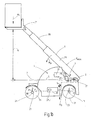
- FIGS. 1a and 1b is in a highly simplified functional sketch as a whole with 1 designated control device for preventing unacceptably high tilting moments M A at one, with one of at least one actuator 3 movable, especially in the insert length L variable working arm 5 equipped, mobile work machine 7 shown ,
- the mobile work machine 7 is formed in the manner of a telescopic loader.
- a support 9 of the rotatable in at least one direction working arm 5 is associated with a traveling part 11 of the mobile working machine 7.
- the working arm 5 is pivotally connected to the carriage 11 by means of the support 9 to the effect that the working arm 5 in the direction of the FIGS.
- the control device 1 comprises an evaluation and control device 17 with a computing unit CPU for evaluating the signals of the load sensor 13 and the angle sensor 15 and for determining the maximum movement speed V max .
- the evaluation and control unit 17 is also used to control the actuator 3.
- the control device 1 is under main or exclusive use of the evaluation and control device 17 by processing at least the incoming signals of the load sensor 13 and the angle sensor 15 determines a maximum possible, the respective impermissible tilting moment M A preventing movement speed V max for the moving working arm 5. It may also be advantageous to use a further control unit not shown in the figures for this purpose.
- the respective actuating device 3 then controls the working arm 5 so that the determined maximum movement speed V max is not exceeded for each displacement position of the working arm 5.
- a characteristic field is stored as a target specification for the calculated maximum movement speed V max .
- estimation or determination of the load mass m L to be moved can be preceded by using the evaluation and control unit 17, in particular using the arithmetic unit CPU, the load mass m L being the input variable in the calculation for the maximum movement speed V max is received.
- a further sensor 19 for determining at least one further operating parameter of the mobile work machine 7 is provided.
- the further sensor 19 is used in the in Fig. 1a shown embodiment for determining the current mass to be moved m L and is denoted by 20.
- the further sensor 19 is used with the aid of the evaluation and control unit 17 for determining the total mass m G of the mobile machine 7 and is denoted by 25.
- the sensor 25 in this case measures a further support load F 2 on a further travel part 21 of the mobile work machine.
- a center of gravity of the mobile work machine 7 with the help of the incoming signals of the respective load sensor 13 and the respective angle sensor 15 and the sensor 25 are determined.
- the sensor 20 is used to measure the current length of the working arm 5, which is telescopic, the pertinent current length is essentially the distance between the longitudinal axis 37 of the support 9 and a fictitious line of action m L L results, the in the illustration after the Fig. 1 passes through the designated with m L load arrow.
- the effective insertion length L is determined by the already described evaluation and control unit 17 together with the computing unit CPU according to the usual trigonometric functions, which, as shown in FIG Fig. 1a shown, again defined by the length between the longitudinal axis 37 of the support 9 and the already mentioned fictitious line of action.
- the mobile working machine 7 has two driving axles 23, 24, which form the respective driving parts 11, 21. At the driving axes 23, 24 determine the respective assignable sensors 13, 25, the respective support load F 1 , F 2 .
- the hydraulic cylinder 28 is arranged with its cylinder-side and piston rod side end hinged to the mobile machine 7 and the working arm 5.
- the respective working arms 5 are each formed of three mutually telescopic individual members 29, 30, 31.
- the evaluation and control unit 17 controls the actuator 27 by controlling components, such as valves, of a hydraulic control circuit 32 supplying the actuator 27 with hydraulic medium.
- the mobile work machine 7 can be configured manifold and instead of the telescopic handler shown in the form of a loading crane, a wheel loader, an agricultural utility or towing vehicle with front loader or with rear loader or side loader, or in the manner of a construction machine, or in the manner of a military vehicle, such as an armored recovery vehicle.
- the respective driving parts 11, 21, as shown, in the manner of a wheelset 33, 35 may be formed with arranged on each of the driving axle 23, 24 wheels.
- the respective driving parts as chain or caterpillar drive or as a wheelless magnetic suspended part, as is known in particular for industrial trucks, for transport purposes Production or assembly lines are used to train.
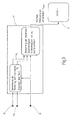
- Fig. 2 shows in the manner of a highly simplified flow chart, the function of the control device 1 in the in Fig. 1a shown embodiment.
- the evaluation and control unit 17 processes the sensor signals of the load sensor 13, the angle sensor 15 and the sensor 20, which are used in the embodiment shown, inter alia, for measuring the telescopic position of the working arm 5 formed as a telescopic arm.
- the evaluation and control unit 17 is able, with the aid of the sensor signals of the angle sensor 15 and the sensor 20, to calculate the effective insertion length L of the working arm 5.
- the signals of the load sensor 13 is of the evaluation and control unit 17, in particular of the computing unit CPU, the current load mass m L calculated.
- the evaluation and control unit 17 selects an associated, maximum movement speed V max for the working arm 5 from a movement speed characteristic field stored in the arithmetic unit CPU as a setpoint presetting. With the aid of the arithmetic unit CPU of the evaluation and control unit 17, the maximum movement speed V max for the working arm 5 can also be calculated without using the movement speed characteristic field.
- the maximum movement speed V max Due to the calculation method according to the invention of the maximum movement speed V max , on the one hand the possible total working speed of the mobile working machine 7 is limited to the most necessary measure and on the other hand, the coupling of dynamic measurement errors, as they are known for example in the use of acceleration sensors on such machines, completely prevented ,
- the calculated maximum movement speed V max thus represents a safe operating parameter for the mobile work machine 7 and its operation, which also limits the working speed of the mobile work machine 7 only to a necessary, the impermissible tilting moment M A preventing measure.
- Fig. 3 is also in the manner of a highly simplified flow chart, the function of the control device 1 in the mobile work machine 7, as in Fig. 1b shown is shown.
- the evaluation and control unit 17 of the control device 1 processes the sensor signals of the load sensor 13, the sensor 25 and the angle sensor 15 in the embodiment shown Total mass m G of the mobile work machine 7 to calculate. Furthermore, due to the measured load distribution at the two driving axes 23, 24 of the mobile working machine, the evaluation and control unit 17 able to calculate the current position of the center of gravity S of the mobile work machine 7. Even with the aid of the sensor signals of the load sensor 13 and the sensor 25, the arithmetic unit CPU can calculate the respective effective insertion length L of the working arm 5 via suitable algorithms, not shown in greater detail. Starting from the measured and calculated values, the evaluation and control unit 17 again selects the respective maximum possible movement speed V max of the working arm 5 from a movement speed characteristic field stored in the arithmetic unit CPU and controls the actuating device 3.
- Procedures for determining the respective maximum movement speed V max of the working arm 5 are influences of dynamic measurement errors that may be significant in the operation of many mobile machines prevented. Unlike in the case of known mobile machines, the operation is thus designed to be safe and, surprisingly, in comparison with the known mobile machines, a higher total operating speed of the mobile machine 7 is made possible, which increases their overall performance. The movement speed also indirectly influences the movement angle and thus prevents a static imbalance of the machines.
Landscapes
- Engineering & Computer Science (AREA)
- Structural Engineering (AREA)
- Mining & Mineral Resources (AREA)
- Civil Engineering (AREA)
- General Engineering & Computer Science (AREA)
- Life Sciences & Earth Sciences (AREA)
- Geology (AREA)
- Mechanical Engineering (AREA)
- Operation Control Of Excavators (AREA)
Claims (11)
- Dispositif de commande pour qu'il n'y ait pas de manière inadmissible de grands couples (MA) de basculement sur une machine (7) mobile fournissant du travail, équipée d'un bras (5) de travail pouvant être déplacé par au moins un dispositif (3) d'actionnement, en étant notamment modifiable dans la longueur (L) d'intervention,
dans lequel un appui (9) du bras (5) de travail tournant dans au moins un sens est associé à au moins une partie (11) de déplacement de la machine (7) mobile fournissant du travail, caractérisé en ce qu'il est prévu au moins un capteur (13) de charge pour la détermination d'une charge (F1) d'appui sur au moins l'une des parties (11) de déplacement et au moins un capteur (15) angulaire pour la détermination d'au moins l'une des positions angulaires du bras (5) de travail par rapport à la partie (11) de déplacement, en ce qu'il y a un appareil (17) d'exploitation et de commande ayant une unité informatique (CPU) pour l'exploitation des signaux du capteur (13) de charge respectif et du capteur (15) d'angle respectif ou pour la commande du dispositif (3) d'actionnement respectif, en ce qu'il est déterminé, pour le bras (5) de travail déplacé en utilisant l'appareil (17) d'exploitation et de commande, au moins par traitement des signaux entrant du capteur (13) de charge et du capteur (15) d'angle, une vitesse (Vmax) possible au maximum prévenant un couple (MA) de basculement inadmissible et en ce que le dispositif (3) d'actionnement respectif commande le bras (7) de travail de manière à ne pas dépasser la vitesse (Vmax) de déplacement maximum déterminée en chaque position de déplacement du bras (5) de travail. - Dispositif de commande suivant la revendication 1, caractérisé en ce que, à l'aide d'une unité informatique, de préférence de l'unité informatique (CPU) de l'appareil (17) d'exploitation et de commande, on calcule la vitesse (Vmax) de déplacement maximum.
- Dispositif de commande suivant la revendication 1, caractérisé en ce que, dans l'unité informatique, de préférence dans l'unité informatique (CPU) de l'appareil (17) d'exploitation et de commande, une courbe caractéristique de vitesse de déplacement est mémorisée comme prescription de consigne pour la vitesse (Vmax) de déplacement maximum calculée.
- Dispositif de commande suivant la revendication 3, caractérisé en ce qu'on effectue, avant le calcul de la vitesse (Vmax) de déplacement maximum du bras (5) de travail, une évaluation ou une détermination de la masse (mL) de charge à déplacer que l'on entre comme grandeur d'entrée dans le calcul de la vitesse (Vmax) de déplacement maximum.
- Dispositif de commande suivant l'une des revendications précédentes, caractérisé en ce que, pour la détermination d'un autre paramètre de fonctionnement de la machine (7) mobile fournissant du travail, comme une masse (mL) de charge à déplacer présentement ou une masse (mG) totale, y compris la position du centre de gravité, les signaux entrants du capteur (3) de charge respectif et du capteur (15) d'angle respectif, ainsi que d'un autre capteur (19) de la machine (7) mobile fournissant du travail sont mis à profit.
- Dispositif de commande suivant l'une des revendications précédentes, caractérisé en ce qu'on se sert, comme autre capteur (19), pour la détermination de la masse (mL) de charge présente à déplacer, d'un capteur qui détermine la longueur (L) efficace d'intervention du bras (5) de travail.
- Dispositif de commande suivant la revendication 5, caractérisé en ce qu'on se sert, comme autre capteur (19) pour la détermination de la masse (mG) totale, y compris du centre de gravité, d'un capteur qui détermine une autre charge (F1) d'appui sur une autre partie (21) de déplacement de la machine (7) mobile fournissant du travail.
- Dispositif de commande suivant l'une des revendications précédentes, caractérisé en ce que la partie (11, 21) de déplacement respective de la machine (7) mobile fournissant du travail a au moins un essieu (23, 24), sur lequel le capteur (13, 25) pouvant être associé respectivement détermine la charge (F1, F2) d'appui.
- Dispositif de commande suivant l'une des revendications précédentes, caractérisé en ce que le dispositif (3) d'actionnement respectif, pour le déplacement du bras (5) de travail par rapport à sa longueur (L) efficace d'intervention et/ou par rapport à sa hauteur (H) de course, est formé d'au moins un actionneur (27), de préférence sous la forme d'un vérin de travail hydraulique.
- Dispositif de commande suivant l'une des revendications précédentes, caractérisé en ce que le bras (5) de travail qui peut être déplacé est en soi rigide ou formé d'une pluralité d'éléments (29, 30, 31) individuels télescopables les uns par rapport aux autres ou articulés les uns avec les autres.
- Dispositif de commande suivant l'une des revendications précédentes, caractérisé en ce que la machine (7) mobile fournissant du travail est constituée à la manière d'une grue de chargement, d'une chargeuse télescopique, d'un chargeur sur roue, d'un véhicule de traction agricole à chargeur avant ou à chargeur arrière ou à chargeur latéral ou à la manière d'un engin de chantier ou à la manière d'un véhicule militaire et en ce que la partie (11, 21) de déplacement respective est constituée à la manière d'un essieu (33, 35), d'un entraînement à chaîne ou d'un entraînement à chenille ou d'une partie à sustentation magnétique.
Applications Claiming Priority (2)
| Application Number | Priority Date | Filing Date | Title |
|---|---|---|---|
| DE201110108874 DE102011108874A1 (de) | 2011-07-28 | 2011-07-28 | Steuervorrichtung |
| PCT/EP2012/003150 WO2013013821A1 (fr) | 2011-07-28 | 2012-07-25 | Dispositif de commande |
Publications (2)
| Publication Number | Publication Date |
|---|---|
| EP2736833A1 EP2736833A1 (fr) | 2014-06-04 |
| EP2736833B1 true EP2736833B1 (fr) | 2015-09-16 |
Family
ID=46601742
Family Applications (1)
| Application Number | Title | Priority Date | Filing Date |
|---|---|---|---|
| EP12741251.8A Not-in-force EP2736833B1 (fr) | 2011-07-28 | 2012-07-25 | Système de commande |
Country Status (3)
| Country | Link |
|---|---|
| EP (1) | EP2736833B1 (fr) |
| DE (1) | DE102011108874A1 (fr) |
| WO (1) | WO2013013821A1 (fr) |
Cited By (5)
| Publication number | Priority date | Publication date | Assignee | Title |
|---|---|---|---|---|
| CN107905272A (zh) * | 2017-11-29 | 2018-04-13 | 黄力 | 一种伸缩式液压挖掘机 |
| CN110958987A (zh) * | 2017-07-17 | 2020-04-03 | 曼尼通公司 | 装卸机的控制 |
| WO2023016771A1 (fr) | 2021-08-13 | 2023-02-16 | Danfoss Power Solutions Gmbh & Co Ohg | Chargeuse télescopique améliorée |
| DE102021128580A1 (de) | 2021-11-03 | 2023-05-04 | Kramer-Werke Gmbh | Baumaschine oder landwirtschaftliche Maschine |
| EP4242160A1 (fr) | 2022-03-08 | 2023-09-13 | Kramer-Werke GmbH | Machine de construction ou machine agricole |
Families Citing this family (7)
| Publication number | Priority date | Publication date | Assignee | Title |
|---|---|---|---|---|
| BR112015014457A2 (pt) | 2012-12-21 | 2017-11-21 | Alios Biopharma Inc | composto ou sal farmaceuticamente aceitável do mesmo e composição farmacêutica e respectivos usos e processos para melhorar ou tratar infecção de hcv, para inibir a atividade da ns5b polimerase do vírus da hepatite c e a replicação de vírus da hepatite c |
| GB2516632B (en) * | 2013-07-26 | 2017-11-29 | Jc Bamford Excavators Ltd | A method of weighing a load |
| DE102014013018A1 (de) | 2014-09-02 | 2016-03-03 | Hydac System Gmbh | Hydraulisches System |
| BR112017003874A2 (pt) | 2014-09-15 | 2018-01-23 | Crown Equip Corp | empilhadeira. |
| WO2016123735A1 (fr) * | 2015-02-02 | 2016-08-11 | Guangxi Liugong Machinery Co., Ltd. | Système de levage destiné à un engin de chantier |
| EP3431435B1 (fr) * | 2017-07-17 | 2020-04-22 | Manitou Bf | Commande d'une machine de manutention |
| DE102018105907A1 (de) | 2018-03-14 | 2019-09-19 | Terex Deutschland GmbH | Verfahren zur Ermittlung des Gewichts einer von einer Lademaschine aufgenommenen Last und Lademaschine hierfür |
Family Cites Families (14)
| Publication number | Priority date | Publication date | Assignee | Title |
|---|---|---|---|---|
| DE2033469B2 (de) * | 1970-07-07 | 1979-01-18 | Carl Metz Gmbh, 7500 Karlsruhe | Kippmomentabhängige Leitersteuerung |
| JP3252006B2 (ja) * | 1993-03-10 | 2002-01-28 | 株式会社タダノ | ブーム付き作業車の制御装置 |
| US6378653B1 (en) * | 1998-12-28 | 2002-04-30 | Kabushiki Kaisha Aichi Corporation | Travel and rotation control device for boom lift |
| JP3717328B2 (ja) * | 1999-02-25 | 2005-11-16 | 株式会社アイチコーポレーション | クローラ式ブーム作業車の安全装置 |
| JP3301416B2 (ja) * | 1999-08-23 | 2002-07-15 | 株式会社豊田自動織機 | 産業車両におけるマスト傾動速度制御装置 |
| US6473679B1 (en) * | 1999-12-10 | 2002-10-29 | Caterpillar Inc. | Angular velocity control and associated method for a boom of a machine |
| JP2002265199A (ja) * | 2001-03-07 | 2002-09-18 | Aichi Corp | 作業用車両の安全装置 |
| GB2390595B (en) * | 2002-07-12 | 2005-08-24 | Bamford Excavators Ltd | Control system for a machine |
| JP2004231335A (ja) * | 2003-01-29 | 2004-08-19 | Aichi Corp | 高所作業車のブーム作動制御装置 |
| DE10304658A1 (de) | 2003-02-05 | 2004-08-19 | Bosch Rexroth Ag | Flurförderfahrzeug |
| DE102005012004B4 (de) * | 2004-04-07 | 2020-09-24 | Linde Material Handling Gmbh | Flurförderzeug mit erhöhter statischer/quasistatischer und dynamischer Kippstabilität |
| JP4741834B2 (ja) * | 2004-12-14 | 2011-08-10 | 株式会社アイチコーポレーション | ブーム作業車のノンストップ作動制御装置 |
| DE102009018072A1 (de) | 2009-04-20 | 2010-10-21 | Robert Bosch Gmbh | Mobile Arbeitsmaschine mit Beschleunigungssensor |
| JP5543741B2 (ja) * | 2009-08-10 | 2014-07-09 | 古河ユニック株式会社 | クレーンの転倒防止装置 |
-
2011
- 2011-07-28 DE DE201110108874 patent/DE102011108874A1/de not_active Withdrawn
-
2012
- 2012-07-25 EP EP12741251.8A patent/EP2736833B1/fr not_active Not-in-force
- 2012-07-25 WO PCT/EP2012/003150 patent/WO2013013821A1/fr not_active Ceased
Cited By (8)
| Publication number | Priority date | Publication date | Assignee | Title |
|---|---|---|---|---|
| CN110958987A (zh) * | 2017-07-17 | 2020-04-03 | 曼尼通公司 | 装卸机的控制 |
| CN110958987B (zh) * | 2017-07-17 | 2021-04-02 | 曼尼通公司 | 装卸机的控制 |
| CN107905272A (zh) * | 2017-11-29 | 2018-04-13 | 黄力 | 一种伸缩式液压挖掘机 |
| WO2023016771A1 (fr) | 2021-08-13 | 2023-02-16 | Danfoss Power Solutions Gmbh & Co Ohg | Chargeuse télescopique améliorée |
| DE102021121163A1 (de) | 2021-08-13 | 2023-02-16 | Danfoss Power Solutions Gmbh & Co. Ohg | Verbesserter Teleskoplader |
| DE102021128580A1 (de) | 2021-11-03 | 2023-05-04 | Kramer-Werke Gmbh | Baumaschine oder landwirtschaftliche Maschine |
| EP4242160A1 (fr) | 2022-03-08 | 2023-09-13 | Kramer-Werke GmbH | Machine de construction ou machine agricole |
| DE102022105449A1 (de) | 2022-03-08 | 2023-09-14 | Kramer-Werke Gmbh | Baumaschine oder Landmaschine |
Also Published As
| Publication number | Publication date |
|---|---|
| DE102011108874A1 (de) | 2013-01-31 |
| WO2013013821A1 (fr) | 2013-01-31 |
| EP2736833A1 (fr) | 2014-06-04 |
Similar Documents
| Publication | Publication Date | Title |
|---|---|---|
| EP2736833B1 (fr) | Système de commande | |
| DE102009037880B4 (de) | Mobile Arbeitsmaschine mit einer Regelvorrichtung mit einem Arbeitsarm und Verfahren zur Arbeitspunktregelung eines Arbeitsarms einer mobilen Arbeitsmaschine | |
| EP1772333B1 (fr) | Engin de travail mobile a stabilisateurs | |
| DE102008020595B4 (de) | Verfahren zur Schwingungsdämpfung bei Flurförderzeugen | |
| EP2843378B1 (fr) | Machine de travail dotée d'un dispositif de levage et d'un dispositif de pesée | |
| DE102008020592B4 (de) | Verfahren zur Schwingungsdämpfung bei Flurförderzeugen | |
| EP3571113B1 (fr) | Engin de travail | |
| EP3337317B1 (fr) | Suspension d'une rampe de pulvérisation pour une machine agricole | |
| DE102013017240A1 (de) | System zur Ermittlung des Arbeitszyklus | |
| DE202013012756U1 (de) | Stabilisierung einer Forstarbeitseinheit | |
| DE102020124867B4 (de) | Verbesserte Hydraulikvorrichtung | |
| DE102021203367A1 (de) | Magnetorheologische fluid-joysticksysteme für arbeitsfahrzeuge, die unbeabsichtigte joystick-bewegungen reduzieren | |
| EP3296249B1 (fr) | Machine de travail articulée | |
| EP2421791B1 (fr) | Machine de travail mobile présentant un accéléromètre | |
| DE102016106459A1 (de) | Arbeitsfahrzeug mit Knick-Gelenk-Lenkung und lastabhängiger Lenkwinkelbegrenzung | |
| EP3141114B1 (fr) | Systeme d'epandage et procede d'epandage | |
| EP3440932B1 (fr) | Réglage active des vibrations | |
| DE102020212648A1 (de) | Elektrohydraulische Anbaugerätesteuerung System und Verfahren | |
| EP3670428B1 (fr) | Procédé de détermination de chargement d'un chariot de manutention et chariot de manutention | |
| DE102016225045A1 (de) | Mobilkran | |
| EP3456584B1 (fr) | Véhicule de transport de charges et son procédé de fonctionnement | |
| EP3798028B1 (fr) | Machine agricole et procédé pour diriger une machine agricole | |
| DE102023121709A1 (de) | Vorrichtung mit Gelenkarm und Verfahren zum Steuern eines solchen | |
| EP4269705B1 (fr) | Procédé d'amélioration de la régulation de l'angle de nivellement d'une machine de travail | |
| DE102023213198A1 (de) | Verfahren zur Bestimmung eines Gewichts einer durch einen Ausleger einer Arbeitsmaschine aufgenommenen Last |
Legal Events
| Date | Code | Title | Description |
|---|---|---|---|
| PUAI | Public reference made under article 153(3) epc to a published international application that has entered the european phase |
Free format text: ORIGINAL CODE: 0009012 |
|
| 17P | Request for examination filed |
Effective date: 20131218 |
|
| AK | Designated contracting states |
Kind code of ref document: A1 Designated state(s): AL AT BE BG CH CY CZ DE DK EE ES FI FR GB GR HR HU IE IS IT LI LT LU LV MC MK MT NL NO PL PT RO RS SE SI SK SM TR |
|
| DAX | Request for extension of the european patent (deleted) | ||
| RIC1 | Information provided on ipc code assigned before grant |
Ipc: E02F 9/24 20060101ALI20141118BHEP Ipc: E02F 9/26 20060101ALI20141118BHEP Ipc: B66C 23/90 20060101ALI20141118BHEP Ipc: B66F 17/00 20060101AFI20141118BHEP Ipc: E02F 9/20 20060101ALI20141118BHEP |
|
| GRAP | Despatch of communication of intention to grant a patent |
Free format text: ORIGINAL CODE: EPIDOSNIGR1 |
|
| INTG | Intention to grant announced |
Effective date: 20150526 |
|
| GRAS | Grant fee paid |
Free format text: ORIGINAL CODE: EPIDOSNIGR3 |
|
| GRAA | (expected) grant |
Free format text: ORIGINAL CODE: 0009210 |
|
| AK | Designated contracting states |
Kind code of ref document: B1 Designated state(s): AL AT BE BG CH CY CZ DE DK EE ES FI FR GB GR HR HU IE IS IT LI LT LU LV MC MK MT NL NO PL PT RO RS SE SI SK SM TR |
|
| REG | Reference to a national code |
Ref country code: GB Ref legal event code: FG4D Free format text: NOT ENGLISH |
|
| REG | Reference to a national code |
Ref country code: CH Ref legal event code: EP |
|
| REG | Reference to a national code |
Ref country code: IE Ref legal event code: FG4D Free format text: LANGUAGE OF EP DOCUMENT: GERMAN |
|
| REG | Reference to a national code |
Ref country code: AT Ref legal event code: REF Ref document number: 749646 Country of ref document: AT Kind code of ref document: T Effective date: 20151015 |
|
| REG | Reference to a national code |
Ref country code: DE Ref legal event code: R096 Ref document number: 502012004591 Country of ref document: DE |
|
| REG | Reference to a national code |
Ref country code: NL Ref legal event code: MP Effective date: 20150916 |
|
| PG25 | Lapsed in a contracting state [announced via postgrant information from national office to epo] |
Ref country code: FI Free format text: LAPSE BECAUSE OF FAILURE TO SUBMIT A TRANSLATION OF THE DESCRIPTION OR TO PAY THE FEE WITHIN THE PRESCRIBED TIME-LIMIT Effective date: 20150916 Ref country code: LV Free format text: LAPSE BECAUSE OF FAILURE TO SUBMIT A TRANSLATION OF THE DESCRIPTION OR TO PAY THE FEE WITHIN THE PRESCRIBED TIME-LIMIT Effective date: 20150916 Ref country code: LT Free format text: LAPSE BECAUSE OF FAILURE TO SUBMIT A TRANSLATION OF THE DESCRIPTION OR TO PAY THE FEE WITHIN THE PRESCRIBED TIME-LIMIT Effective date: 20150916 Ref country code: NO Free format text: LAPSE BECAUSE OF FAILURE TO SUBMIT A TRANSLATION OF THE DESCRIPTION OR TO PAY THE FEE WITHIN THE PRESCRIBED TIME-LIMIT Effective date: 20151216 Ref country code: GR Free format text: LAPSE BECAUSE OF FAILURE TO SUBMIT A TRANSLATION OF THE DESCRIPTION OR TO PAY THE FEE WITHIN THE PRESCRIBED TIME-LIMIT Effective date: 20151217 |
|
| REG | Reference to a national code |
Ref country code: LT Ref legal event code: MG4D |
|
| PG25 | Lapsed in a contracting state [announced via postgrant information from national office to epo] |
Ref country code: SE Free format text: LAPSE BECAUSE OF FAILURE TO SUBMIT A TRANSLATION OF THE DESCRIPTION OR TO PAY THE FEE WITHIN THE PRESCRIBED TIME-LIMIT Effective date: 20150916 Ref country code: HR Free format text: LAPSE BECAUSE OF FAILURE TO SUBMIT A TRANSLATION OF THE DESCRIPTION OR TO PAY THE FEE WITHIN THE PRESCRIBED TIME-LIMIT Effective date: 20150916 Ref country code: RS Free format text: LAPSE BECAUSE OF FAILURE TO SUBMIT A TRANSLATION OF THE DESCRIPTION OR TO PAY THE FEE WITHIN THE PRESCRIBED TIME-LIMIT Effective date: 20150916 |
|
| PG25 | Lapsed in a contracting state [announced via postgrant information from national office to epo] |
Ref country code: NL Free format text: LAPSE BECAUSE OF FAILURE TO SUBMIT A TRANSLATION OF THE DESCRIPTION OR TO PAY THE FEE WITHIN THE PRESCRIBED TIME-LIMIT Effective date: 20150916 |
|
| PG25 | Lapsed in a contracting state [announced via postgrant information from national office to epo] |
Ref country code: EE Free format text: LAPSE BECAUSE OF FAILURE TO SUBMIT A TRANSLATION OF THE DESCRIPTION OR TO PAY THE FEE WITHIN THE PRESCRIBED TIME-LIMIT Effective date: 20150916 Ref country code: ES Free format text: LAPSE BECAUSE OF FAILURE TO SUBMIT A TRANSLATION OF THE DESCRIPTION OR TO PAY THE FEE WITHIN THE PRESCRIBED TIME-LIMIT Effective date: 20150916 Ref country code: IS Free format text: LAPSE BECAUSE OF FAILURE TO SUBMIT A TRANSLATION OF THE DESCRIPTION OR TO PAY THE FEE WITHIN THE PRESCRIBED TIME-LIMIT Effective date: 20160116 Ref country code: SK Free format text: LAPSE BECAUSE OF FAILURE TO SUBMIT A TRANSLATION OF THE DESCRIPTION OR TO PAY THE FEE WITHIN THE PRESCRIBED TIME-LIMIT Effective date: 20150916 Ref country code: CZ Free format text: LAPSE BECAUSE OF FAILURE TO SUBMIT A TRANSLATION OF THE DESCRIPTION OR TO PAY THE FEE WITHIN THE PRESCRIBED TIME-LIMIT Effective date: 20150916 |
|
| REG | Reference to a national code |
Ref country code: FR Ref legal event code: PLFP Year of fee payment: 5 |
|
| PG25 | Lapsed in a contracting state [announced via postgrant information from national office to epo] |
Ref country code: PL Free format text: LAPSE BECAUSE OF FAILURE TO SUBMIT A TRANSLATION OF THE DESCRIPTION OR TO PAY THE FEE WITHIN THE PRESCRIBED TIME-LIMIT Effective date: 20150916 Ref country code: RO Free format text: LAPSE BECAUSE OF FAILURE TO SUBMIT A TRANSLATION OF THE DESCRIPTION OR TO PAY THE FEE WITHIN THE PRESCRIBED TIME-LIMIT Effective date: 20150916 Ref country code: PT Free format text: LAPSE BECAUSE OF FAILURE TO SUBMIT A TRANSLATION OF THE DESCRIPTION OR TO PAY THE FEE WITHIN THE PRESCRIBED TIME-LIMIT Effective date: 20160118 |
|
| REG | Reference to a national code |
Ref country code: DE Ref legal event code: R097 Ref document number: 502012004591 Country of ref document: DE |
|
| PLBE | No opposition filed within time limit |
Free format text: ORIGINAL CODE: 0009261 |
|
| STAA | Information on the status of an ep patent application or granted ep patent |
Free format text: STATUS: NO OPPOSITION FILED WITHIN TIME LIMIT |
|
| 26N | No opposition filed |
Effective date: 20160617 |
|
| PG25 | Lapsed in a contracting state [announced via postgrant information from national office to epo] |
Ref country code: DK Free format text: LAPSE BECAUSE OF FAILURE TO SUBMIT A TRANSLATION OF THE DESCRIPTION OR TO PAY THE FEE WITHIN THE PRESCRIBED TIME-LIMIT Effective date: 20150916 |
|
| PG25 | Lapsed in a contracting state [announced via postgrant information from national office to epo] |
Ref country code: SI Free format text: LAPSE BECAUSE OF FAILURE TO SUBMIT A TRANSLATION OF THE DESCRIPTION OR TO PAY THE FEE WITHIN THE PRESCRIBED TIME-LIMIT Effective date: 20150916 |
|
| REG | Reference to a national code |
Ref country code: CH Ref legal event code: PL |
|
| PG25 | Lapsed in a contracting state [announced via postgrant information from national office to epo] |
Ref country code: MC Free format text: LAPSE BECAUSE OF FAILURE TO SUBMIT A TRANSLATION OF THE DESCRIPTION OR TO PAY THE FEE WITHIN THE PRESCRIBED TIME-LIMIT Effective date: 20150916 |
|
| PG25 | Lapsed in a contracting state [announced via postgrant information from national office to epo] |
Ref country code: LI Free format text: LAPSE BECAUSE OF NON-PAYMENT OF DUE FEES Effective date: 20160731 Ref country code: CH Free format text: LAPSE BECAUSE OF NON-PAYMENT OF DUE FEES Effective date: 20160731 |
|
| REG | Reference to a national code |
Ref country code: IE Ref legal event code: MM4A |
|
| REG | Reference to a national code |
Ref country code: FR Ref legal event code: PLFP Year of fee payment: 6 |
|
| PG25 | Lapsed in a contracting state [announced via postgrant information from national office to epo] |
Ref country code: IE Free format text: LAPSE BECAUSE OF NON-PAYMENT OF DUE FEES Effective date: 20160725 |
|
| PG25 | Lapsed in a contracting state [announced via postgrant information from national office to epo] |
Ref country code: LU Free format text: LAPSE BECAUSE OF NON-PAYMENT OF DUE FEES Effective date: 20160725 |
|
| PG25 | Lapsed in a contracting state [announced via postgrant information from national office to epo] |
Ref country code: HU Free format text: LAPSE BECAUSE OF FAILURE TO SUBMIT A TRANSLATION OF THE DESCRIPTION OR TO PAY THE FEE WITHIN THE PRESCRIBED TIME-LIMIT; INVALID AB INITIO Effective date: 20120725 Ref country code: SM Free format text: LAPSE BECAUSE OF FAILURE TO SUBMIT A TRANSLATION OF THE DESCRIPTION OR TO PAY THE FEE WITHIN THE PRESCRIBED TIME-LIMIT Effective date: 20150916 Ref country code: CY Free format text: LAPSE BECAUSE OF FAILURE TO SUBMIT A TRANSLATION OF THE DESCRIPTION OR TO PAY THE FEE WITHIN THE PRESCRIBED TIME-LIMIT Effective date: 20150916 |
|
| REG | Reference to a national code |
Ref country code: FR Ref legal event code: PLFP Year of fee payment: 7 |
|
| PG25 | Lapsed in a contracting state [announced via postgrant information from national office to epo] |
Ref country code: MK Free format text: LAPSE BECAUSE OF FAILURE TO SUBMIT A TRANSLATION OF THE DESCRIPTION OR TO PAY THE FEE WITHIN THE PRESCRIBED TIME-LIMIT Effective date: 20150916 Ref country code: MT Free format text: LAPSE BECAUSE OF FAILURE TO SUBMIT A TRANSLATION OF THE DESCRIPTION OR TO PAY THE FEE WITHIN THE PRESCRIBED TIME-LIMIT Effective date: 20150916 |
|
| PG25 | Lapsed in a contracting state [announced via postgrant information from national office to epo] |
Ref country code: BG Free format text: LAPSE BECAUSE OF FAILURE TO SUBMIT A TRANSLATION OF THE DESCRIPTION OR TO PAY THE FEE WITHIN THE PRESCRIBED TIME-LIMIT Effective date: 20150916 |
|
| PG25 | Lapsed in a contracting state [announced via postgrant information from national office to epo] |
Ref country code: TR Free format text: LAPSE BECAUSE OF FAILURE TO SUBMIT A TRANSLATION OF THE DESCRIPTION OR TO PAY THE FEE WITHIN THE PRESCRIBED TIME-LIMIT Effective date: 20150916 Ref country code: AL Free format text: LAPSE BECAUSE OF FAILURE TO SUBMIT A TRANSLATION OF THE DESCRIPTION OR TO PAY THE FEE WITHIN THE PRESCRIBED TIME-LIMIT Effective date: 20150916 |
|
| PGFP | Annual fee paid to national office [announced via postgrant information from national office to epo] |
Ref country code: FR Payment date: 20230626 Year of fee payment: 12 |
|
| PGFP | Annual fee paid to national office [announced via postgrant information from national office to epo] |
Ref country code: BE Payment date: 20230614 Year of fee payment: 12 |
|
| PGFP | Annual fee paid to national office [announced via postgrant information from national office to epo] |
Ref country code: IT Payment date: 20230705 Year of fee payment: 12 Ref country code: GB Payment date: 20230510 Year of fee payment: 12 Ref country code: AT Payment date: 20230720 Year of fee payment: 12 |
|
| PGFP | Annual fee paid to national office [announced via postgrant information from national office to epo] |
Ref country code: DE Payment date: 20230731 Year of fee payment: 12 |
|
| REG | Reference to a national code |
Ref country code: DE Ref legal event code: R119 Ref document number: 502012004591 Country of ref document: DE |
|
| REG | Reference to a national code |
Ref country code: AT Ref legal event code: MM01 Ref document number: 749646 Country of ref document: AT Kind code of ref document: T Effective date: 20240725 |
|
| GBPC | Gb: european patent ceased through non-payment of renewal fee |
Effective date: 20240725 |
|
| PG25 | Lapsed in a contracting state [announced via postgrant information from national office to epo] |
Ref country code: DE Free format text: LAPSE BECAUSE OF NON-PAYMENT OF DUE FEES Effective date: 20250201 |
|
| PG25 | Lapsed in a contracting state [announced via postgrant information from national office to epo] |
Ref country code: AT Free format text: LAPSE BECAUSE OF NON-PAYMENT OF DUE FEES Effective date: 20240725 Ref country code: BE Free format text: LAPSE BECAUSE OF NON-PAYMENT OF DUE FEES Effective date: 20240731 |
|
| PG25 | Lapsed in a contracting state [announced via postgrant information from national office to epo] |
Ref country code: FR Free format text: LAPSE BECAUSE OF NON-PAYMENT OF DUE FEES Effective date: 20240731 |
|
| PG25 | Lapsed in a contracting state [announced via postgrant information from national office to epo] |
Ref country code: GB Free format text: LAPSE BECAUSE OF NON-PAYMENT OF DUE FEES Effective date: 20240725 |
|
| REG | Reference to a national code |
Ref country code: BE Ref legal event code: MM Effective date: 20240731 |
|
| PG25 | Lapsed in a contracting state [announced via postgrant information from national office to epo] |
Ref country code: IT Free format text: LAPSE BECAUSE OF NON-PAYMENT OF DUE FEES Effective date: 20240725 |