EP2738954A2 - Empfänger für die Wiederherstellung von universellen Diensten in einem Spotbeam-Satellitenübertragungssystem und Verfahren - Google Patents
Empfänger für die Wiederherstellung von universellen Diensten in einem Spotbeam-Satellitenübertragungssystem und Verfahren Download PDFInfo
- Publication number
- EP2738954A2 EP2738954A2 EP13193787.2A EP13193787A EP2738954A2 EP 2738954 A2 EP2738954 A2 EP 2738954A2 EP 13193787 A EP13193787 A EP 13193787A EP 2738954 A2 EP2738954 A2 EP 2738954A2
- Authority
- EP
- European Patent Office
- Prior art keywords
- antenna elements
- signal
- transmitted
- sub
- receiver
- Prior art date
- Legal status (The legal status is an assumption and is not a legal conclusion. Google has not performed a legal analysis and makes no representation as to the accuracy of the status listed.)
- Withdrawn
Links
- 238000000034 method Methods 0.000 title claims abstract description 45
- 230000005540 biological transmission Effects 0.000 title claims abstract description 10
- 238000004891 communication Methods 0.000 claims abstract description 22
- 230000010287 polarization Effects 0.000 claims abstract description 15
- 230000008569 process Effects 0.000 claims description 7
- 238000005070 sampling Methods 0.000 claims 1
- 238000010586 diagram Methods 0.000 description 7
- 238000012545 processing Methods 0.000 description 5
- 230000008901 benefit Effects 0.000 description 4
- 230000002596 correlated effect Effects 0.000 description 2
- 238000005516 engineering process Methods 0.000 description 2
- 230000007613 environmental effect Effects 0.000 description 2
- 230000004048 modification Effects 0.000 description 2
- 238000012986 modification Methods 0.000 description 2
- 238000011084 recovery Methods 0.000 description 2
- 230000000306 recurrent effect Effects 0.000 description 2
- 230000007704 transition Effects 0.000 description 2
- 239000011800 void material Substances 0.000 description 2
- RNAMYOYQYRYFQY-UHFFFAOYSA-N 2-(4,4-difluoropiperidin-1-yl)-6-methoxy-n-(1-propan-2-ylpiperidin-4-yl)-7-(3-pyrrolidin-1-ylpropoxy)quinazolin-4-amine Chemical compound N1=C(N2CCC(F)(F)CC2)N=C2C=C(OCCCN3CCCC3)C(OC)=CC2=C1NC1CCN(C(C)C)CC1 RNAMYOYQYRYFQY-UHFFFAOYSA-N 0.000 description 1
- 101100402572 Arabidopsis thaliana MS5 gene Proteins 0.000 description 1
- 230000003044 adaptive effect Effects 0.000 description 1
- 238000004458 analytical method Methods 0.000 description 1
- 230000009286 beneficial effect Effects 0.000 description 1
- 230000015556 catabolic process Effects 0.000 description 1
- 239000000470 constituent Substances 0.000 description 1
- 238000006731 degradation reaction Methods 0.000 description 1
- 230000001627 detrimental effect Effects 0.000 description 1
- 238000007726 management method Methods 0.000 description 1
- 239000000463 material Substances 0.000 description 1
- 238000012544 monitoring process Methods 0.000 description 1
- 238000005457 optimization Methods 0.000 description 1
- 230000000063 preceeding effect Effects 0.000 description 1
- 230000011664 signaling Effects 0.000 description 1
- 238000001228 spectrum Methods 0.000 description 1
- 230000003068 static effect Effects 0.000 description 1
Images


Classifications
-
- H—ELECTRICITY
- H04—ELECTRIC COMMUNICATION TECHNIQUE
- H04B—TRANSMISSION
- H04B7/00—Radio transmission systems, i.e. using radiation field
- H04B7/02—Diversity systems; Multi-antenna system, i.e. transmission or reception using multiple antennas
- H04B7/04—Diversity systems; Multi-antenna system, i.e. transmission or reception using multiple antennas using two or more spaced independent antennas
- H04B7/08—Diversity systems; Multi-antenna system, i.e. transmission or reception using multiple antennas using two or more spaced independent antennas at the receiving station
- H04B7/0802—Diversity systems; Multi-antenna system, i.e. transmission or reception using multiple antennas using two or more spaced independent antennas at the receiving station using antenna selection
- H04B7/0805—Diversity systems; Multi-antenna system, i.e. transmission or reception using multiple antennas using two or more spaced independent antennas at the receiving station using antenna selection with single receiver and antenna switching
- H04B7/0814—Diversity systems; Multi-antenna system, i.e. transmission or reception using multiple antennas using two or more spaced independent antennas at the receiving station using antenna selection with single receiver and antenna switching based on current reception conditions, e.g. switching to different antenna when signal level is below threshold
-
- H—ELECTRICITY
- H04—ELECTRIC COMMUNICATION TECHNIQUE
- H04B—TRANSMISSION
- H04B7/00—Radio transmission systems, i.e. using radiation field
- H04B7/02—Diversity systems; Multi-antenna system, i.e. transmission or reception using multiple antennas
- H04B7/04—Diversity systems; Multi-antenna system, i.e. transmission or reception using multiple antennas using two or more spaced independent antennas
- H04B7/08—Diversity systems; Multi-antenna system, i.e. transmission or reception using multiple antennas using two or more spaced independent antennas at the receiving station
- H04B7/0802—Diversity systems; Multi-antenna system, i.e. transmission or reception using multiple antennas using two or more spaced independent antennas at the receiving station using antenna selection
- H04B7/0805—Diversity systems; Multi-antenna system, i.e. transmission or reception using multiple antennas using two or more spaced independent antennas at the receiving station using antenna selection with single receiver and antenna switching
- H04B7/0808—Diversity systems; Multi-antenna system, i.e. transmission or reception using multiple antennas using two or more spaced independent antennas at the receiving station using antenna selection with single receiver and antenna switching comparing all antennas before reception
- H04B7/0811—Diversity systems; Multi-antenna system, i.e. transmission or reception using multiple antennas using two or more spaced independent antennas at the receiving station using antenna selection with single receiver and antenna switching comparing all antennas before reception during preamble or gap period
-
- H—ELECTRICITY
- H04—ELECTRIC COMMUNICATION TECHNIQUE
- H04B—TRANSMISSION
- H04B7/00—Radio transmission systems, i.e. using radiation field
- H04B7/02—Diversity systems; Multi-antenna system, i.e. transmission or reception using multiple antennas
- H04B7/10—Polarisation diversity; Directional diversity
-
- H—ELECTRICITY
- H04—ELECTRIC COMMUNICATION TECHNIQUE
- H04B—TRANSMISSION
- H04B7/00—Radio transmission systems, i.e. using radiation field
- H04B7/02—Diversity systems; Multi-antenna system, i.e. transmission or reception using multiple antennas
- H04B7/12—Frequency diversity
-
- H—ELECTRICITY
- H04—ELECTRIC COMMUNICATION TECHNIQUE
- H04B—TRANSMISSION
- H04B7/00—Radio transmission systems, i.e. using radiation field
- H04B7/14—Relay systems
- H04B7/15—Active relay systems
- H04B7/185—Space-based or airborne stations; Stations for satellite systems
- H04B7/1853—Satellite systems for providing telephony service to a mobile station, i.e. mobile satellite service
- H04B7/18539—Arrangements for managing radio, resources, i.e. for establishing or releasing a connection
- H04B7/18541—Arrangements for managing radio, resources, i.e. for establishing or releasing a connection for handover of resources
-
- H—ELECTRICITY
- H04—ELECTRIC COMMUNICATION TECHNIQUE
- H04B—TRANSMISSION
- H04B7/00—Radio transmission systems, i.e. using radiation field
- H04B7/14—Relay systems
- H04B7/15—Active relay systems
- H04B7/204—Multiple access
- H04B7/2041—Spot beam multiple access
-
- H—ELECTRICITY
- H04—ELECTRIC COMMUNICATION TECHNIQUE
- H04L—TRANSMISSION OF DIGITAL INFORMATION, e.g. TELEGRAPHIC COMMUNICATION
- H04L7/00—Arrangements for synchronising receiver with transmitter
- H04L7/0079—Receiver details
Definitions
- the present invention generally relates to a satellite receiver system and method for receiving a signal, and more particularly, to such a receiver system and method for switching among a plurality of antenna elements to receive a signal.
- a receiver system can include multiple antennas for receiving different signals or the same signals.
- One example of such a system is where a first antenna is used to receive a first signal, and a second antenna is configured to receive a second signal.
- the first and second antennas generally cannot be used to receive both the first and second signals because the signals are being transmitted differently (i.e., transmitted in different modulation formats) or being transmitted from different sources.
- a receiver system that uses a blind antenna switching method.
- a blind antenna switching method is where a first antenna is used to receive a signal, and the receiver system switches to the second antenna when a power level of the signal received by the first antenna is below a predetermined level.
- the receiver system using the blind antenna switching method does not know the power level of the signal received by the second antenna until the receiver system switches to the second antenna.
- the receiver system is assuming that since the power level of the signal received by the first antenna is below the predetermined value that the signal received by the second antenna is likely to be equal to or better than the power level of the signal received by the first antenna prior to switching.
- the receiver system blindly switches back to the first antenna when the power level of the signal received by the second antenna is below a predetermined level.
- the power level of the signal being received by the other antenna is unknown until the receiver system switches to that antenna.
- Satellite radio systems employ spot beam technology to enable more services to be transmitted to users.
- the spot beam technology allows the service provider to optimize the available transmit power for user needs, An example would be traffic information or regional news that is highly desirable for users in a given location, but not as desirable for users in a distant location.
- Spot beams can take the form of a different frequency or polarization.
- the receiver When the satellite transmission has time aligned the universal services, then the receiver does not have to be concerned incorrect symbol recovery and frame synchronization. This can be achieved with the two relatively new satellite radio standards DVB-SH and E-SDR.
- the receiver When a simple antenna is used and the spot beams are on opposite polarizations, the receiver must tell the antenna to switch to the desired polarization. However, the receiver may not know if the different polarization is available. It is always desirable to use the strongest signal possible. When the satellite transmission system has time aligned the universal services, then the receiver does not have to worry about incorrect symbol recovery and frame synchronization.
- the receiver can just jump between the two polarizations to determine which one to use. However, when the other polarization is not present, the interleaver and FEC are filled with "junk" information.
- a receiver provides the following functionalities:
- a receiver system includes a plurality of antenna elements, a switching device, and a controller. At least a portion of the plurality of antenna elements receive a transmitted signal, wherein the transmitted signal includes a plurality of sub-channels that are transmitted in predetermined time intervals.
- the switching device is in communication with the plurality of antenna elements, and switches among single antenna elements to receive the transmitted signal.
- the controller is in communication with the switching device, and commands the switching device to select each of the plurality of antenna elements separately in predetermined periods of time based upon the predetermined time intervals of each of the sub-channels.
- a power level of the signal is determined during the predetermined period of time that corresponds to the predetermined time intervals, and the controller commands the switching device to switch to an antenna element based upon the determined power level.
- a receiver system includes a plurality of antenna elements, a switching device, and a receiving module. At least a portion of the plurality of antenna elements receives a transmitted signal that is time division multiplexed (TDM), such that the transmitted signal includes a plurality of sub-channels that are transmitted in predetermined time intervals.
- the switching device is in communication with the plurality of antenna elements, and switches among single antenna elements to receive the transmitted signal.
- the receiving module houses a controller that is in communication with the switching device, wherein the controller commands the switching device to select each of the plurality of antenna elements separately in predetermined periods of time based upon the predetermined time intervals of each of the sub-channels.
- the receiving module processes the transmitted signal to produce an output based upon a selected sub-channel, and determines a power level of the transmitted signal at at least a portion of the plurality of antenna elements during a predetermined period of time that corresponds to the time interval of a non-selected sub-channel, wherein the controller commands the switching device to switch to an antenna element with a greater determined power level to receive the transmitted signal during the time interval of the selected sub-channel.
- a method of switching among antenna elements in a receiver system includes the steps of transmitting a signal including a plurality of sub-channels, wherein the sub-channels are transmitted in predetermined time intervals, and receiving the transmitted signal by an antenna element of a plurality of antenna elements, wherein the transmitted signal containing a selected sub-channel is processed.
- the method further includes the steps of switching among at least a portion of the plurality of antenna elements, and receiving the transmitted signal during a predetermined period of time that corresponds to the predetermined time intervals of the non-selected sub-channels, determining a power level of the transmitted signal during the predetermined period of time, and switching to the antenna element receiving the transmitted signal at a greater determined power level during the predetermined time interval of the selected sub-channel.
- the problem addressed by the present invention is how to maintain a seamless transition from one spot beam to another when the user transitions between two regions.
- the present invention provides a solution to the above described issues wherein the satellite radio receiver quickly switches to another polarization/frequency to check if the signal is present during times that contain no user content. This is accomplished by employing a transmission parameter signal that is transmitted periodically that rarely changes. During this time, the receiver can evaluate new signals and switch back. Since this signal rarely changes, the user will not notice any mutes.
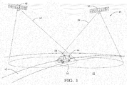
- a motorway 40 for ground vehicles 44 transits a terrestrial region 42.
- a spot beam satellite transmission system 46 provides signal coverage to the entire region 42 and, in the illustrated embodiment, includes two satellites 48 and 50.
- Each satellite 48 and 50 comprises a discrete signal source, collectively producing first and second adjacent overlapping spot beam loci 52 and 54 within region 42.
- Vehicle 44 is illustrated in the area if intersection 56 of the overlapping spot beam loci 52 and 54, wherein a single radio signal receiver 58 carried with the vehicle 44 is capable of simultaneously receiving signals from both satellites 48 and 50.
- the transmitted signals from each satellite 48 and 50 are time division multiplexed (TDM).
- TDM time division multiplexed
- each TDM signal includes a plurality of sub-channels, which appear to be transferred simultaneously, but are individually transmitted during recurrent time intervals that are fixed in length.
- the sub-channels of the transmitted TDM signal appear as data bursts, such that the data received in the selected sub-channel is processed to emit an output during the period of time that the selected sub-channel and other sub-channels or non-selected sub-channels, are being transmitted, without leaving a null or void in the output.
- the non-selected sub channels are the sub-channels that contain data that is not currently being used or processed to emit the output.
- an existing system that transmits such a TDM signal is the Sirius® satellite system.
- exemplary time correlated diagrams of a first signal 60 associated with spot 52 and a second signal 62 associated with spot 54 are illustrated.
- the signals 60 and 62 are transmitted in alignment as illustrated, wherein the SYNC portion of the signals are correlated and contain static information, along with a synchronization signal.
- common channels 1 of signals 60 and 62 have the same content, as do common channels 2.
- Signal 1 channels 1 - 5 differ in timing, duration and/or content from signal 2 channels 1 - 5.
- the receiver 58 can tune to from spot beam 52 to spot beam 54, or vice versa, and check for availability. If the other beam is available and stronger in signal strength, the receiver can stay tuned to the new channel, otherwise it will tune back to the original signal. If the user is tuned to a channel that is not available on a stronger beam, the receiver can notify the user.
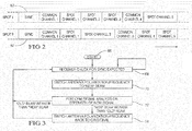
- FIG. 3 a flow chart illustrating the logic steps for switching between available channels illustrates one embodiment of the invention.
- the switching can be achieved by switching between multiple antennas carried by the vehicle 44, or reconfiguring the single receiver antenna to alter its frequency or polarization characteristics.
- the method of switching between available channels is affected by a reference identifier 64.
- the method starts at step 66 and proceeds to step 68 where the receiver checks for an expected SYNC signal portion. If expected SYNC signal portion is not present, the logic returns to step 68 to re-check for an expected SYNC signal portion. This continues until a SYNC signal if found.
- the method proceeds to step 70 wherein the radio controller switches the active antenna polarization/frequency to another "new" beam signal.
- the controller performs a signal analysis to determine the strength of the "new" signal. This step could include metrics such as a frame header, preamble sequences and the like.
- the control returns to original step 68 to recheck for a SYNC signal. If the signal strength of the "new" beam signal is weaker than that of the previous "old” beam signal, the controller moves to step 74 and switches the antenna polarization/frequency back to its original condition.
- FIGS 4 - 9 describe a receiver system and method for switching among a plurality of antenna elements to receive a signal applicable for practicing the present invention.
- At least a portion of plurality of antenna elements receive a transmitted signal, such that the transmitted signal includes a plurality of sub-channels that are transmitted in predetermined time intervals.
- a switching device is in communication with the plurality of antenna elements, and switches among single antenna elements to receive the transmitted signal.
- a controller is in communication with the switching device, and commands the switching device to select each of the antenna elements separately in predetermined periods of time based upon the predetermined time intervals of each of the sub-channels.
- a power level of the transmitted signal is determined during the predetermined period of time that corresponds to the predetermined time intervals, and the controller commands the switching device to switch to an antenna element based upon the determined power level.
- a receiver system is generally shown at reference identifier 10.
- the receiver system 10 includes a plurality of antenna elements 12, wherein at least a portion of the plurality of antenna elements 12 receive a transmitted signal.
- the transmitted signal includes a plurality of sub-channels that are transmitted in predetermined time intervals, such that the desired data is transmitted within at least one of the sub-channels, as described in greater detail below.
- the receiver system 10 also includes a switching device 14 that is in communication with a plurality of antenna elements 12. The switching device selects a single antenna element of the plurality of antenna elements 12 to receive the transmitted signal.
- the receiver system 10 further includes a controller 16 that is in communication with the switching device 14.
- the controller 16 commands the switching device 14 to select each of the plurality of antenna elements 12 separately in predetermined periods of time based upon the predetermined time intervals of each of the sub-channels.
- a power level of the transmitted signal is determined during a predetermined period of time that corresponds to the predetermined time intervals of the sub-channels, as described in greater detail herein.
- the transmitted signal is time division multiplexed (TDM).
- TDM time division multiplexed
- a TDM signal includes a plurality of sub-channels, which appear to be transferred simultaneously, but are individually transmitted during recurrent time intervals that are fixed in length.
- the sub-channels of the transmitted TDM signal appear as data bursts, such that the data received in the selected sub-channel is processed to emit an output during the period of time that the selected sub-channel and other sub-channels or non-selected sub-channels, are being transmitted, without leaving a null or void in the output.
- the non-selected sub-channels are the sub-channels that contain data that is not currently being used or processed to emit the output.
- an existing system that transmits such a TDM signal is the Sirius® satellite system.
- Figs. 4 - 7 an exemplary diagram of sub-channels being transmitted in a TDM signal is shown in Fig. 5 .
- sub-channel TDM2 contains the data that is currently desired (i.e., TDM2 is the selected sub-channel and TDM1, TDM3, TDM4, and TDM5 are the non-selected sub-channels)
- one of the antenna elements 12 receives the transmitted TDM signal, and the data received during the TDM2 sub-channel time interval is processed to produce the emitted output.
- the data processed from the TDM2 sub-channel is received during a first predetermined time interval (e.g., TDM2_1), and processed during the time intervals where sub-channels TDM3_1, TDM4_1, TDM5_1, and TDM1_2 are received.
- TDM2_1 a first predetermined time interval
- the selected sub-channel is processed and an output is emitted based upon the selected sub-channel during the period of time that corresponds to the predetermined time intervals of the non-selected sub-channels, and the predetermined time interval of the selected sub-channel.
- the receiving system 10 can alternate which antenna element 12 is being used to receive the signal to determine if the signal can be received at a greater power level using a different antenna element 12.
- the receiver system 10 does not have to lock to the phase of the signal received by the different antenna elements 12.
- the antenna element 12 can be selected, and the power level of the signal can be determined without being required to process the received signal. According to one embodiment shown in Fig.
- the switching device 14 is housed in a receiver module generally indicated at 18, and each antenna element 12 is housed in a separate antenna module generally indicated at 20.
- the antenna module 20 also houses at least one low-noise amplifier (LNA) 22, wherein one LNA 22 is in communication with the antenna element 12.
- LNA low-noise amplifier
- a filter 24 is in communication between multiple LNAs 22, which typically removes undesirable noise from the received signal.
- the receiver module 18 houses a signal processor 26 in communication with the switching device 14.
- the signal processor 26 is in communication with a memory device 27 that includes one or more software routines for processing the received signal. Additionally or alternatively, the signal processor 26 includes circuitry for processing the received signal.
- the signal processor 26 down-converts the radio frequency (RF) of the received signal from the antenna element 12 to a lower frequency, and digitally demodulates the received signal.
- RF radio frequency
- the signal processor 26 can digitally or include circuitry for processing the received signal in a desirable manner. Additionally, when the non-selected sub-channels are received, the signal processor 26 can determine the power level of the received signal without processing the received signal to produce an emitted output, according to one embodiment.
- an audio output is produced by the receiver module 18 based upon the received signal using a speaker 28. It should be appreciated by those skilled in the art that the output emitted by the receiver module 18 can be an audio output, a video output, or a combination thereof. Additionally, the signal processor 26 is in communication with the controller 16, such that the controller 16 can control the switching device 14 based upon the signal received and processed by the signal processor 26, according to one embodiment.
- an alternate embodiment of the receiver system 10 is generally shown at reference identifier 110, wherein like reference characters indicate like elements.
- An antenna module 120 houses the plurality of antenna elements 12. Additionally, the antenna module 120 houses the LNAs 22 that are in communication with the antenna elements 12, the switching device 14 that is in communication with the LNAs 22 to switch among the antenna elements 12, and a filter 24 in communication with the switching device 14, according to one embodiment. Additionally, a receiver module 118 can include the signal processor 26 and controller 16, according to a disclosed embodiment.
- an antenna module 220 houses the antenna elements 12, the LNAs 22, the filter 24, and a down-converter device 30.
- the down-converter device 30 converts the RF level of the received signal from the antenna element 12 to a lower frequency, such that the received signal can be communicated through the receiver system 210.
- a receiver module 218 can house the switching device 14, the controller 16, a signal processor 226, and the memory device 27.
- the signal processor 226 includes the circuitry and/or implements one or more software routines stored in the memory device 27 for digitally demodulating the received signal.
- the receiver module 18, 118, 218 can include additional circuitry and/or one or more software routines in order to perform other signal processing functions.
- a method of switching antenna elements 12 is generally shown in Fig. 8 at reference identifier 300.
- the method 300 starts at step 302, and proceeds to step 304, where the signal is transmitted.
- the transmitted signal is a TDM signal.
- the selected sub-channel is received by the antenna element 12.
- the signal processor 26, 226 processes the received signal during the time interval of the selected sub-channel and along the time intervals of the non-selected sub-routines to emit the output.
- step 308 if it is determined at step 308 that the predetermined time interval for the selected sub-channel has lapsed, then the method 300 proceeds to step 310, where the switching device 14 switches among the antenna elements 12. Thus, each of the antenna elements 12 is used to receive the signal.
- step 312 it is determined if the signal power level is greater using other antenna elements 12 than the antenna element 12 originally being used to receive the transmitted signal.
- the signal processor 26, 226 processes the received signal during the time intervals of the non-selected sub-channels to determine the power level, but not to produce the emitted output.
- step 312 If it is determined at step 312 that the antenna element 12 originally used to receive the transmitted signal has a greater signal power level, then the method 300 returns to step 306 to receive the transmitted signal during the time interval of the selected sub-channel. However, if it is determined at step 312 that the signal power level is greater at another antenna element 12, then the method 300 proceeds to step 314, wherein the switching device 14 switches to the antenna element 12 that receives the signal at a greater power level in order to receive the transmitted signal during the time interval of the selected sub-channel. The method 300 then ends at step 316.
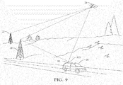
- the receiver system 10 receives a signal that is transmitted from a transmitter 32 and retransmitted by a satellite 34, such that the receiver system 10 is used in a satellite digital audio radio (SDAR).
- SDAR satellite digital audio radio
- the receiver system 10 is used with a vehicle 36.
- a terrestrial repeater 38 can be in communication with the satellite 34, such that the terrestrial repeater 38 receives the satellite RF signal from the satellite 34, and re-transmits the signal as a terrestrial RF signal, according to one embodiment.
- the receiver system 10, 110, 210 and method 300 can switch among antenna elements 12 to determine which antenna element 12 receives the transmitted signal at a greater power level without needing to fully process the received signal, such as lock in a phase of the received signal at each antenna element 12. Since the signal is transmitted having sub-channels that are individually transmitted in predetermined time intervals, the receiver system 10, 110, 210 can switch among the antenna elements 12 during the predetermined time period associated with the predetermined time intervals of the sub-channels that are not selected.
- the receiver system 10 can determine the power level of the received signal in order for the receiver system 10 to make a determination as to whether or not to switch to a different antenna element 12 when receiving the transmitted signal during the selected sub-channel time interval based upon the power level of the received signal at the particular antenna element 12, and not making a blind switch.
Landscapes
- Engineering & Computer Science (AREA)
- Computer Networks & Wireless Communication (AREA)
- Signal Processing (AREA)
- Physics & Mathematics (AREA)
- Astronomy & Astrophysics (AREA)
- Aviation & Aerospace Engineering (AREA)
- General Physics & Mathematics (AREA)
- Radio Relay Systems (AREA)
- Radio Transmission System (AREA)
Applications Claiming Priority (1)
| Application Number | Priority Date | Filing Date | Title |
|---|---|---|---|
| US13/688,542 US20140146921A1 (en) | 2012-11-29 | 2012-11-29 | Receiver for recovering universal services in a spot beam satellite transmission system and method |
Publications (2)
| Publication Number | Publication Date |
|---|---|
| EP2738954A2 true EP2738954A2 (de) | 2014-06-04 |
| EP2738954A3 EP2738954A3 (de) | 2014-07-30 |
Family
ID=49639755
Family Applications (1)
| Application Number | Title | Priority Date | Filing Date |
|---|---|---|---|
| EP13193787.2A Withdrawn EP2738954A3 (de) | 2012-11-29 | 2013-11-21 | Empfänger für die Wiederherstellung von universellen Diensten in einem Spotbeam-Satellitenübertragungssystem und Verfahren |
Country Status (2)
| Country | Link |
|---|---|
| US (1) | US20140146921A1 (de) |
| EP (1) | EP2738954A3 (de) |
Families Citing this family (3)
| Publication number | Priority date | Publication date | Assignee | Title |
|---|---|---|---|---|
| US9312944B2 (en) | 2013-12-26 | 2016-04-12 | Aruba Networks, Inc. | System, apparatus and method for integrated wireless link management for a multi-polarized antenna system |
| US10277338B2 (en) * | 2016-03-23 | 2019-04-30 | Telefonaktiebolaget Lm Ericsson (Publ) | Efficient scheduling of beam quality measurement signals to multiple wireless devices |
| CN108124293B (zh) * | 2017-12-15 | 2020-07-31 | 中国人民解放军32039部队 | 空间异构一体化网络中话音业务切换方法及装置 |
Citations (10)
| Publication number | Priority date | Publication date | Assignee | Title |
|---|---|---|---|---|
| US20020052180A1 (en) | 2000-08-09 | 2002-05-02 | Hughes Electronics | System and method for mobility management for a satellite based packet data system |
| US20040137842A1 (en) | 2002-10-21 | 2004-07-15 | Tadayoshi Iwata | Method of receiving signals through satellites |
| US20070192805A1 (en) | 2006-02-15 | 2007-08-16 | Atc Technologies, Llc | Adaptive spotbeam broadcasting, systems, methods and devices for high bandwidth content distribution over satellite |
| US7580798B2 (en) | 2001-05-15 | 2009-08-25 | Psychogenics, Inc. | Method for predicting treatment classes using animal behavior informatics |
| US7773697B2 (en) | 2005-03-23 | 2010-08-10 | Delphi Technologies, Inc. | Method to demodulate amplitude offsets in a differential modulation system |
| US7822149B2 (en) | 2005-06-02 | 2010-10-26 | Delphi Technologies, Inc. | Method to enable single frequency network optimization |
| US7830983B2 (en) | 2005-03-01 | 2010-11-09 | Delphi Technologies, Inc. | Method to minimize degradation in a D-MPSK hierarchical modulation system |
| US7957333B2 (en) | 2007-09-19 | 2011-06-07 | Delphi Technologies, Inc. | Receiver system and method for switching among a plurality of antenna elements to receive a signal |
| US8014479B2 (en) | 2005-12-22 | 2011-09-06 | Delphi Technologies, Inc. | Method and system for communicating sub-synchronization signals using a phase rotator |
| US8107557B2 (en) | 2007-04-13 | 2012-01-31 | Delphi Delco Electronics Europe Gmbh | Reception system having a switching arrangement for suppressing change-over interference in the case of antenna diversity |
Family Cites Families (4)
| Publication number | Priority date | Publication date | Assignee | Title |
|---|---|---|---|---|
| US6768457B2 (en) * | 2001-03-02 | 2004-07-27 | Fuba Automotive Gmbh & Co. Kg | Diversity systems for receiving digital terrestrial and/or satellite radio signals for motor vehicles |
| US7447171B2 (en) * | 2004-06-14 | 2008-11-04 | Xm Satellite Radio, Inc. | Antenna diversity system |
| US8787310B2 (en) * | 2008-04-18 | 2014-07-22 | Kyocera Corporation | Mobile station device and transmission power control method |
| CA2731034A1 (en) * | 2008-06-30 | 2010-01-14 | Sirius Xm Radio Inc. | Interface between a switched diversity antenna system and a digital radio receiver |
-
2012
- 2012-11-29 US US13/688,542 patent/US20140146921A1/en not_active Abandoned
-
2013
- 2013-11-21 EP EP13193787.2A patent/EP2738954A3/de not_active Withdrawn
Patent Citations (10)
| Publication number | Priority date | Publication date | Assignee | Title |
|---|---|---|---|---|
| US20020052180A1 (en) | 2000-08-09 | 2002-05-02 | Hughes Electronics | System and method for mobility management for a satellite based packet data system |
| US7580798B2 (en) | 2001-05-15 | 2009-08-25 | Psychogenics, Inc. | Method for predicting treatment classes using animal behavior informatics |
| US20040137842A1 (en) | 2002-10-21 | 2004-07-15 | Tadayoshi Iwata | Method of receiving signals through satellites |
| US7830983B2 (en) | 2005-03-01 | 2010-11-09 | Delphi Technologies, Inc. | Method to minimize degradation in a D-MPSK hierarchical modulation system |
| US7773697B2 (en) | 2005-03-23 | 2010-08-10 | Delphi Technologies, Inc. | Method to demodulate amplitude offsets in a differential modulation system |
| US7822149B2 (en) | 2005-06-02 | 2010-10-26 | Delphi Technologies, Inc. | Method to enable single frequency network optimization |
| US8014479B2 (en) | 2005-12-22 | 2011-09-06 | Delphi Technologies, Inc. | Method and system for communicating sub-synchronization signals using a phase rotator |
| US20070192805A1 (en) | 2006-02-15 | 2007-08-16 | Atc Technologies, Llc | Adaptive spotbeam broadcasting, systems, methods and devices for high bandwidth content distribution over satellite |
| US8107557B2 (en) | 2007-04-13 | 2012-01-31 | Delphi Delco Electronics Europe Gmbh | Reception system having a switching arrangement for suppressing change-over interference in the case of antenna diversity |
| US7957333B2 (en) | 2007-09-19 | 2011-06-07 | Delphi Technologies, Inc. | Receiver system and method for switching among a plurality of antenna elements to receive a signal |
Also Published As
| Publication number | Publication date |
|---|---|
| US20140146921A1 (en) | 2014-05-29 |
| EP2738954A3 (de) | 2014-07-30 |
Similar Documents
| Publication | Publication Date | Title |
|---|---|---|
| EP0977376B1 (de) | Ein Zeitmultiplex-Ansatz für Rundfunk mit mehreren Sendern | |
| US10368327B2 (en) | Method and system for signal communications | |
| US7817958B2 (en) | System for and method of providing remote coverage area for wireless communications | |
| US20180316479A1 (en) | A method and system for satellite communication | |
| EP1990966A2 (de) | System und Verfahren zum Senden und Empfangen von digitalen Satellitenfunksignalen über eine ungerade Zahl von Frequenzschlitzen | |
| US7447171B2 (en) | Antenna diversity system | |
| US7957333B2 (en) | Receiver system and method for switching among a plurality of antenna elements to receive a signal | |
| EP2738954A2 (de) | Empfänger für die Wiederherstellung von universellen Diensten in einem Spotbeam-Satellitenübertragungssystem und Verfahren | |
| CN100399723C (zh) | 混合多点卫星广播系统中有效利用频率的系统和方法 | |
| US7398050B2 (en) | Method and apparatus for processing air-borne digital data received in a motor vehicle | |
| EA002604B1 (ru) | Цифровая вещательная система, использующая спутниковое прямое вещание и наземный ретранслятор | |
| EP1883173A2 (de) | Verfahren und System zum Senden und Empfangen von Informationen über digitale Satelliten-Radioprogramme für mehrere Kanäle | |
| KR20090063266A (ko) | 지상 리피터 및 기지국 | |
| EP2005616A2 (de) | System und verfahren für datenkommunikation aus mehreren quellen | |
| KR102339244B1 (ko) | 위성 IoT 단말 및 이를 이용한 단방향 데이터 송신 방법 | |
| EP2190134B1 (de) | Kommunikationssystem und Verfahren zur Signalkommunikation | |
| KR20050018525A (ko) | 위성 디지털 멀티미디어 방송 시스템 에이 에서 시분할다중화 방식의 경로를 이용하는 장치 및 방법 | |
| US7512159B2 (en) | Method for variable performance in communication systems | |
| CA2532838A1 (en) | Method and system for converting streaming digital data to fm modulated data | |
| KR20120053523A (ko) | Flo 및 flo-ev 데이터의 동시 수신을 위한 시스템 및 방법 | |
| Sallam et al. | A geo satellite system for broadcast audio and multimedia services targeting mobile users in europe | |
| EP2161861A2 (de) | Empfängervorrichtung und Verfahren zum Empfangen mehrerer Signale | |
| US20080293359A1 (en) | System and method of communicating and re-using frequencies within terrestrial and satellite signal paths | |
| KR100492256B1 (ko) | 위성 방송 중계기 | |
| Yi | TDM framing for gap filler operation in satellite digital multimedia broadcasting System A |
Legal Events
| Date | Code | Title | Description |
|---|---|---|---|
| PUAI | Public reference made under article 153(3) epc to a published international application that has entered the european phase |
Free format text: ORIGINAL CODE: 0009012 |
|
| 17P | Request for examination filed |
Effective date: 20131121 |
|
| AK | Designated contracting states |
Kind code of ref document: A2 Designated state(s): AL AT BE BG CH CY CZ DE DK EE ES FI FR GB GR HR HU IE IS IT LI LT LU LV MC MK MT NL NO PL PT RO RS SE SI SK SM TR |
|
| AX | Request for extension of the european patent |
Extension state: BA ME |
|
| PUAL | Search report despatched |
Free format text: ORIGINAL CODE: 0009013 |
|
| RIC1 | Information provided on ipc code assigned before grant |
Ipc: H04B 7/10 20060101ALN20140618BHEP Ipc: H04B 7/12 20060101ALN20140618BHEP Ipc: H04B 7/08 20060101AFI20140618BHEP |
|
| AK | Designated contracting states |
Kind code of ref document: A3 Designated state(s): AL AT BE BG CH CY CZ DE DK EE ES FI FR GB GR HR HU IE IS IT LI LT LU LV MC MK MT NL NO PL PT RO RS SE SI SK SM TR |
|
| AX | Request for extension of the european patent |
Extension state: BA ME |
|
| R17P | Request for examination filed (corrected) |
Effective date: 20150130 |
|
| RBV | Designated contracting states (corrected) |
Designated state(s): AL AT BE BG CH CY CZ DE DK EE ES FI FR GB GR HR HU IE IS IT LI LT LU LV MC MK MT NL NO PL PT RO RS SE SI SK SM TR |
|
| STAA | Information on the status of an ep patent application or granted ep patent |
Free format text: STATUS: THE APPLICATION IS DEEMED TO BE WITHDRAWN |
|
| 18D | Application deemed to be withdrawn |
Effective date: 20170601 |