EP2740645B1 - Système de mécanisation de la commande manuelle d'organe de commande de véhicule ferroviaire - Google Patents
Système de mécanisation de la commande manuelle d'organe de commande de véhicule ferroviaire Download PDFInfo
- Publication number
- EP2740645B1 EP2740645B1 EP13195817.5A EP13195817A EP2740645B1 EP 2740645 B1 EP2740645 B1 EP 2740645B1 EP 13195817 A EP13195817 A EP 13195817A EP 2740645 B1 EP2740645 B1 EP 2740645B1
- Authority
- EP
- European Patent Office
- Prior art keywords
- actuating device
- control member
- rail vehicle
- fact
- detachable connection
- Prior art date
- Legal status (The legal status is an assumption and is not a legal conclusion. Google has not performed a legal analysis and makes no representation as to the accuracy of the status listed.)
- Active
Links
Images


Classifications
-
- B—PERFORMING OPERATIONS; TRANSPORTING
- B61—RAILWAYS
- B61D—BODY DETAILS OR KINDS OF RAILWAY VEHICLES
- B61D7/00—Hopper cars
- B61D7/14—Adaptations of hopper elements to railways
- B61D7/16—Closure elements for discharge openings
- B61D7/24—Opening or closing means
- B61D7/28—Opening or closing means hydraulic or pneumatic
Definitions
- the present invention relates to the field of railway vehicles and more particularly to that of the control of the operation of a mechanical equipment of a rail vehicle, in particular a railway vehicle for the transport of goods or maintenance of railways.
- ballast boats which are railcars used to transport ballast to a railroad yard and drop it off.
- a ballast tank comprises a hollow body forming hoppers for the ballast and mounted on bogies for circulation on a railway track, the removal and distribution of the ballast along the railway being effected via openings. arranged in the lower part of the hoppers and each closed selectively by a mobile hatch, for example a hatch with a helmet.
- a ballast tank can include any number of hatches, but there are generally three hatches on each side of the tank divided into a front hatch, a central hatch and a rear hatch.
- ballast The distribution of the ballast along a railway is ensured by the continuous but slow advance, generally at about 5 km / h, of a ballast train containing any number of ballast boats, generally between three and twenty-two, which are used one after the other as the ballast is removed.
- each hatch namely its opening and closing movements
- a respective centralized levers on a platform of the ballast and controlling the operation of the hatches via devices transforming a movement of pivoting a lever respectively in a first direction and a second direction in a movement of the corresponding hatch in the opening and closing respectively of said hatch.
- the opening and closing maneuvers of the hatches and the control of the good distribution of the ballast are performed by at least two operators, an operator manually operating the levers of a ballast tank while a second operator operates next to the ballast tank to control the removal of the ballast and to transmit the appropriate instructions to the first operator.
- the mechanization systems above are in theory capable of satisfactorily solving the problems of safety and difficulty for the operators.
- the mechanization system must be chosen or modified according to the specific configuration of the trap door control of the ballast on which it is desired to install it, which in practice further limits the interest of mechanizing the control of the hatches.
- control member such as levers, flywheels, pedals, etc., which themselves control any type of mechanical equipment of a railway vehicle, such as a bunker hatch, a sunroof in a transport wagon etc.
- the mechanization system comprising a device for actuating the control member or members which comprises on the one hand connecting means removable to the rail vehicle, the mechanization system being characterized in that the actuating device comprises, on the other hand, detachable connecting means to the gripping portion of the or actuators, the actuating device being able to move the detachable connection means to the gripping portion of the or each control member relative to the detachable connecting means to the rail vehicle, so as to actuate, in use, the or each control member by moving its gripping portion.
- the actuating device comprises manual means of transport and maneuvering.
- the detachable connection means of the actuating device to the gripping portion of the control member or bodies and the means for removably connecting the actuating device to the railway vehicle are advantageously clamping connection means, which allows easy installation. and fast actuating device while taking into account the shapes and dimensions of the area where it is attached to the vehicle and the gripping portion of the or each control member, which may vary depending on the ballast boats.
- the means for detachably connecting the actuating device to the railway vehicle may comprise a support assembly adapted to be removably attached to the railway vehicle, the actuating device being connected, preferably removably, to the support assembly.
- the support assembly may be formed by a number of separate support pieces, one for each controller to be mechanized.
- the support assembly is advantageously constituted by a single piece forming an interface between the rail vehicle and the actuating device.
- the actuating device may comprise, for the or each control member, an actuating mechanism capable of actuating the respective control member, the actuating mechanism being connected on the one hand to the detachable connection means of the control device. actuation to the railway vehicle and, secondly, the detachable connecting means of the actuating device to the gripping portion of the respective control member.
- the or each actuating mechanism may comprise an actuator producing as output a movement of the same type as that of the gripping portion of the control member to which the actuating mechanism is connected, as well as means for transmitting the movement of output of the actuator to said control member.
- a "type" of motion is, for example, a rotational movement about one or more axes, a translational movement in one or more directions, or any compound motion of rotation and translation.
- the expression “same type” is understood to mean that if the movement of the gripping portion of the control member is a pivoting movement about an axis, then the output movement of the actuator is a pivotal movement about an axis parallel to the pivot axis of the gripping portion.
- the or each actuating mechanism may comprise an actuator producing at output a movement of a type different from that of the gripping portion of the control member to which the actuating mechanism is connected, as well as means of transforming the output movement of the actuator into the movement of said control member.
- the actuator of the actuating mechanism produces a translational movement output and is connected to an articulated arm assembly which is articulated to the detachable connection means to the gripping portion of the lever and whose arms are articulated so as to translating a translational movement produced by the actuator into one of opposite first and second translational directions into a pivoting movement of the lever in a respective first and second opposite pivoting direction.
- the means for removably connecting the actuating device to the railway vehicle comprise a support assembly as defined above
- the means for removably connecting the actuating device to the railway vehicle comprise a support assembly as defined above
- from the support assembly extend two parallel plates spaced apart from each other by providing between them a space for the passage of the articulated arm assembly, one end of the actuator being pivotally mounted about an axis extending between the two plates, in the free end region thereof, the other end of the actuator being support assembly side and hinged at one end of a first arm, itself pivotally mounted around an axis extending between the two plates in the support assembly-side region, the other end of the first arm being pivotally connected to one end of a second arm, the other end of which is pivotally connected to the lever, by the removable connection means, the pivot axes of the actuator, the first arm and the second arm being parallel to the pivot axis of the lever.
- the two parallel plates extend from a base plate provided with removable connection means to the support assembly.
- the system according to the present invention further comprises a control and power supply device for controlling the actuating device and providing it with the energy necessary to actuate the control device or bodies.
- Such a control device and power supply can, for example, be permanently placed on an existing railway vehicle or consist of a device already present on the rail vehicle.
- control device and power supply comprises detachable connecting means to the rail vehicle or the actuating device and, preferably, also manual means of transport and maneuvering.
- the support assembly where appropriate the interface piece, and / or the housing advantageously comprise means for removably hooking the housing to the support assembly.
- connection means of the automation part to the actuating device can be wired or wireless.
- the energy source portion is capable of supplying the energy required by the actuating device in the form it requires.
- the energy source portion may comprise a hydraulic pump and hydraulic connection means to the actuating device, where appropriate to the hydraulic actuator or actuators, so as to form a hydraulic circuit.
- the energy source portion may comprise an electrical energy storage device and means for charging the electrical energy storage device.
- an electric battery As an example of an electrical energy storage device, it is possible to give an electric battery, the charging means then being able to be constituted by a charger able to receive electrical energy from an external source, for example from an electrical network or from a power source. a generator.
- the energy source portion comprises an electrical energy storage device, for example an electric battery, and means for producing electrical energy by using the movement of the railway vehicle along the track, with a view to at least partially reloading the electrical energy storage device during the movement of the railway vehicle.
- an electrical energy storage device for example an electric battery
- the means for producing electrical energy may consist of a triboelectric generator having means for rubbing against a wheel of the railway vehicle in order to produce electricity.
- the energy source part may comprise firstly an electrical energy storage device, means for charging the electrical energy storage device or production means. electrical energy by using the movement of the rail vehicle along the track and, secondly, a hydraulic pump and hydraulic connection means to the actuating device, where appropriate to the or the hydraulic actuators, so as to form a hydraulic circuit.
- the energy source part may comprise an electrical energy storage device and may be means for charging the electrical energy.
- electrical energy storage device means for producing electrical energy by using the movement of the railway vehicle along the track.
- An example of an electrically-controlled but hydraulically-independent actuator is an actuator comprising one or more hydraulic actuators consisting of autonomous hydraulic cylinders, namely cylinders with integrated hydraulic power unit.
- the mechanization system according to the present invention may furthermore comprise a surveillance camera system comprising connecting means, possibly removable, enabling it to be turned towards the mechanical equipment whose operation is controlled by the control device or devices. , and a radio remote control capable of remotely controlling the automation part and communicating with the surveillance camera system, the radio control comprising a screen for the real-time display of the video taken by the surveillance camera system.
- the mechanization system according to the present invention may furthermore comprise position sensors connected to the automation part so as to communicate to it in real time sensor measurements and that the automation part is servocontrolled by using said sensor measurements.
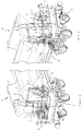
- FIG. 1 it can be seen that there is shown the front of a ballast 1 having a platform 2 on each side of which are pivotally mounted three control levers 3 of three respective traps (not shown) of the ballast tank 1.
- each lever 3 is pivotally mounted on a base 4 fixed to the platform 2.
- each lever 3 comprises a gripping part, by which it is normally actuated by an operator standing on the platform 2, formed by a bar 5 and a yoke 6 to which the bar 5 is attached and which is connected to pivoting at the base 4, a locking hook 7 being provided and the three levers 3 pivoting about the same axis.
- a mechanization system is installed to mechanize the manual control of the three levers 3 on the left side of the platform 2 on the Figures 1 and 2 .
- the mechanization system comprises an actuating device 8 and a control and power supply device 9.
- the actuating device 8 comprises a support part 10 and, for each lever 3, an actuating mechanism 11 and a fastener 12.
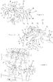
- the support piece 10 is a mechanically welded piece formed by a hollow bar 13 of rectangular section on one side of which are welded two plates 14 extending perpendicular to it and having in their free end region a portion 15 projecting downwards, the free end terminating an elongated portion 16 provided with a through-hole 17.
- the distance between the portion 15 and the bar 13 is equal to the width of the plate 18 of the platform 2 on which the bases 4 are fixed, so that the portion 15 and the bar 13 are in contact with a slice of the plate 18.
- the support piece 10 is provided with means for detachably connecting the plate 18 by clamping, which are formed, for each plate 14, by a locking handle 19, a rod 20 and a latch 21.
- the locking handle 19 is pivotally mounted at 22 on the plate 14, in the bar-side region 13 and in the upper part of the plate 14, and is connected by the connecting rod 20 to the latch 21 pivotally mounted in 23 on the plate 14 above the portion 15 projecting downwards, the pivot axes of the locking handle 19 and the latch 21 being parallel.
- the pivoting of the locking handle 19 in one direction is transformed, by the rod 20, into a pivoting of the lock 21 in the opposite direction, the pivoting of the lock 21 being guided by a stud 24 carried by the lock 21 and sliding in a opening in an arc 25 formed in the plate 14.
- the lock 21 has a notch 26 formed in the lower part of its side facing the bar 13. As can be seen better on the Figure 6 , the latch 21 and the notch 26 are dimensioned and positioned so that when the locking handle 19 is lowered, as shown in FIGS. Figures 4 and 5 , the edge of the plate 18 is housed in the notch 26.
- the support piece 10 can be removably connected to the plate 18 by clamping between the locks 21 and the bar 13 following the lowering of the locking handles 19, the loosening being obtained simply by raising the handles Locking 18.
- Each attachment element comprises an upper hook 28 and a lower hook 29, whose function will be explained below.
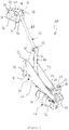
- an actuating mechanism 11 comprises a frame 30, an actuator 31 and an articulated arm assembly 32.
- the frame 30 is a mechanically welded piece formed of a base plate 33 and two parallel plates 34 extending perpendicular to the latter and spaced apart from each other.
- Two parallel vertical slots 35 are provided, one on each vertical side of the mud plate 33, and a notch 36 is provided in the lower edge of the plate 33, each vertically of a slot 35.
- the spacing between the two slots 35, and indeed between the two notches 36, is equal to the spacing between two fastening elements 27 of the same pair.
- each actuating mechanism 11 can be removably connected to the support member 10 by applying the base plate 33 against the support member 10 by engaging each upper hook 28 in the respective slot 35 and each lower hook 29 in the notch. 36 respective.
- the plates 34 are tapered and an axis 37 extends between the end regions of the two plates 34.
- the actuator 31 is a self-contained hydraulic cylinder, comprising a jack 38 and its integrated hydraulic unit 39.
- the body of the jack 38 is pivotally mounted on the shaft 37 and the head of the jack 38 is pivotally connected to the assembly. articulated arms 32.
- the articulated arm assembly 32 is formed by a first arm 40 and a second arm 41.
- the first arm 40 is composed of two curved parallel plates 42 whose first, lower ends are pivotally connected at 43 to the cylinder head. 38 and whose second ends, upper, are pivotally connected at 44 to one end of the second arm 41 which is in the form of a rod.
- Each plate 42 is furthermore pivotally connected by an axis 45 extending between the two plates 34, in the vicinity of the base plate 33.
- the other end of the second arm 41 is pivotally connected at 46 to a fastener 12.
- the fastener 12 constitutes a means of removably connecting the articulated arm assembly 32 to the gripping portion of a lever 3.
- the fastener 12 comprises a tongue 47 on each side of which extends an L-shaped lateral portion 48, welded to the tongue 47 so as to form, in side view, an open U opposite the pivotal connection. with the second arm 41.
- each lateral portion 48 is in recess towards the opposite lateral portion 48.
- each lateral portion 48 On the end of each lateral portion 48 is provided a pair of first legs 50, bottom side of the U, one at the top and one at the bottom, and, free end side, a second tab 51 projecting a distance less than the first legs 50.
- the fastener 12 can be fixed releasably to the lever 3 by passing the tongue 47 and the lateral portions 48 into the opening of the yoke 6 until the first legs 50 abut against the side of the yoke. screed 6.
- the distance between firstly the first tabs 50 and the corresponding second tab 51 is equal to the width of the yoke 6 in the connection region between the latter and the fastener 12, and that the distance between the yokes two side portions 48 is equal to the width of the opening of the yoke 6, so that when the first lugs 50 abut against the yoke 6, the second lug 51 abuts against the opposite side of the yoke 6, the passage of the two parties laterally 48 in the opening the yoke 6 being made possible by the choice for the side portions 48 of a material allowing a slight elastic deformation.
- hooking elements 27 are positioned on the bar 13 so as to correspond to a respective lever 3.
- each actuating mechanism 11 can be removably connected to the support member 10 and to the gripping portion of a lever 3, as shown in FIG. Figure 3 .
- pivot axes of the various parts of the articulated arm assembly 32 are all parallel to each other and are parallel to the pivot axis of the levers 3.
- the actuating mechanism 11 thus makes it possible to mechanize the manual control of the lever 3.
- the fastener 12 can also be releasably connected to a latch 66 by virtue of the articulation of the first and second arms 40, 41, the actuating mechanism 11 being able to be easily transported in this position. by an operator.
- the lock 66 is an integral part of the two plates 34 and having two lateral wings 67 in each of which is formed an opening 68 in which is housed the corresponding lug 51, after slight elastic deformation of the side portions 48.
- the clip 12 is detached. lock 66 simply by pinching the two side portions 48 towards each other to disengage the tabs 51 from the openings 68.
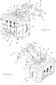
- control device and power supply 9 of the mechanization system removably connected to the support part 10.
- the control device and power supply 9 is in the form of a bag 52 provided with two carrying handles 53 and removable attachment means to the support piece 10 in the form of a fixed plate rigidly on one side of the bag 10 and from which extends two pairs of legs 54 having a central opening 55 in which can pass the elongate portion 16 of the plate 14, the bag 10 being further provided with two locks 56 that the operator can engage in the through hole 17 to lock the bag 10 in position on the support piece 8.
- the bag 10 comprises a battery for supplying the actuators 31 with electrical energy by means of cables (not shown) that are connected to sockets 57 arranged on the cover of the bag 10, a power interface to adapt the output of the battery to the input of the actuator 31, an automation part, serving to control the supply of energy to the actuators 31 and comprising for example a calculator and a series of relays, a radio receiver allowing a operator to control the automation part remotely using a radio control, and a man-machine interface placed on the lid of the bag 10.
- the human-machine interface may include start-up buttons 58, a circuit breaker 59, an emergency stop button 60, run indicators of the battery 61, actuator 62, and so on.
- the battery can be recharged, via a socket 63 on the cover, by an external energy source, such as the electrical network, a generator, this energy source preferably being a source using the circulation of the ballast tank 1 to produce electricity, such as a triboelectric generator in contact with a wheel of the ballast tank 1 or a device mounted on the axle of a bogie.
- an external energy source such as the electrical network, a generator
- this energy source preferably being a source using the circulation of the ballast tank 1 to produce electricity, such as a triboelectric generator in contact with a wheel of the ballast tank 1 or a device mounted on the axle of a bogie.
- the automation part may be connected to the actuators 31 by cables (not shown) or wirelessly.
- the battery it is also possible for the battery to be able to supply other functions of the ballast tank, such as a lighting function or, for example, to supply, via a jack 64, a surveillance camera system filming the area of the hatches and communicating with a radio remote control provided with a display screen so that the operator can control the levers 3 according to what he sees on the screen, a camera on light 65 being provided on the lid.
- a lighting function such as a jack 64, a surveillance camera system filming the area of the hatches and communicating with a radio remote control provided with a display screen so that the operator can control the levers 3 according to what he sees on the screen, a camera on light 65 being provided on the lid.
- the operator can remain on the platform 2 throughout the removal of the ballast, which solves the problems of safety and hardship.
- the mechanization system according to the particular embodiment of the present invention described above allows, if desired, a single operator to perform the removal of the ballast, as follows.
- the operator first fixes the support part 10 on the plate 18, then fixes each actuating mechanism 11, the handling of which is facilitated by the possibility of placing them in the transport position shown in FIG. Figure 12 , to the support piece 10, before attaching it to the respective lever 3, and finally secures the bag 9 on the support piece 10.
- the operator can then control, using a radio remote control, the operation of each of the actuators 31, to lower or raise the lever 3 corresponding.
- the mechanization system according to the present invention makes it possible, on the one hand, to preserve the integrity of the railway vehicle, which in the railroad field makes it possible to have no substantial modification which would give rise to a binding procedure, long and costly to obtain approval for the use of the system on vehicles from the competent administrative services, and secondly to limit the number of systems to be acquired and put in place on the entire fleet of vehicles existing.
Landscapes
- Engineering & Computer Science (AREA)
- Transportation (AREA)
- Mechanical Engineering (AREA)
- Train Traffic Observation, Control, And Security (AREA)
- Vehicle Cleaning, Maintenance, Repair, Refitting, And Outriggers (AREA)
Applications Claiming Priority (2)
| Application Number | Priority Date | Filing Date | Title |
|---|---|---|---|
| FR1203356A FR2998852B1 (fr) | 2012-12-05 | 2012-12-05 | Outillage amovible pour wagons destines a la depose de ballast sur voies ferrees |
| FR1352441A FR2998851B1 (fr) | 2012-12-05 | 2013-03-19 | Systeme de mecanisation de la commande manuelle d'organe de commande de vehicule ferroviaire |
Publications (2)
| Publication Number | Publication Date |
|---|---|
| EP2740645A1 EP2740645A1 (fr) | 2014-06-11 |
| EP2740645B1 true EP2740645B1 (fr) | 2016-05-11 |
Family
ID=49683629
Family Applications (1)
| Application Number | Title | Priority Date | Filing Date |
|---|---|---|---|
| EP13195817.5A Active EP2740645B1 (fr) | 2012-12-05 | 2013-12-05 | Système de mécanisation de la commande manuelle d'organe de commande de véhicule ferroviaire |
Country Status (6)
| Country | Link |
|---|---|
| EP (1) | EP2740645B1 (pl) |
| BE (1) | BE1022496B1 (pl) |
| ES (1) | ES2586067T3 (pl) |
| FR (1) | FR2998851B1 (pl) |
| PL (1) | PL2740645T3 (pl) |
| PT (1) | PT2740645E (pl) |
Cited By (2)
| Publication number | Priority date | Publication date | Assignee | Title |
|---|---|---|---|---|
| WO2020217149A1 (fr) | 2019-04-24 | 2020-10-29 | Novium | Train de ballast à commande d'ouverture et de fermeture de trappes automatique et à alimentation autonome |
| US11268546B2 (en) | 2018-04-02 | 2022-03-08 | Carrier Corporation | Flush pump and hydraulic system |
Families Citing this family (1)
| Publication number | Priority date | Publication date | Assignee | Title |
|---|---|---|---|---|
| CN106926850B (zh) * | 2017-04-24 | 2018-10-26 | 中车眉山车辆有限公司 | 一种铁路漏斗车用轨道式单扇底门独立控制卸货装置 |
Family Cites Families (3)
| Publication number | Priority date | Publication date | Assignee | Title |
|---|---|---|---|---|
| US3899980A (en) * | 1974-07-29 | 1975-08-19 | Florig Equipment Company Inc | Hopper closure assembly |
| US5311822A (en) | 1992-12-07 | 1994-05-17 | Herzog Contracting Corporation | Ballast hopper door control apparatus and method with independently and selectively actuated motors in response to uniquely coded signals |
| FR2929219A1 (fr) * | 2008-03-25 | 2009-10-02 | Sncf | Circuit hydraulique pour wagon, en particulier une ballastiere |
-
2013
- 2013-03-19 FR FR1352441A patent/FR2998851B1/fr not_active Expired - Fee Related
- 2013-12-05 EP EP13195817.5A patent/EP2740645B1/fr active Active
- 2013-12-05 PL PL13195817.5T patent/PL2740645T3/pl unknown
- 2013-12-05 PT PT131958175T patent/PT2740645E/pt unknown
- 2013-12-05 BE BE2013/0816A patent/BE1022496B1/fr not_active IP Right Cessation
- 2013-12-05 ES ES13195817.5T patent/ES2586067T3/es active Active
Cited By (3)
| Publication number | Priority date | Publication date | Assignee | Title |
|---|---|---|---|---|
| US11268546B2 (en) | 2018-04-02 | 2022-03-08 | Carrier Corporation | Flush pump and hydraulic system |
| WO2020217149A1 (fr) | 2019-04-24 | 2020-10-29 | Novium | Train de ballast à commande d'ouverture et de fermeture de trappes automatique et à alimentation autonome |
| DE212020000604U1 (de) | 2019-04-24 | 2021-11-30 | Novium | Schotterzug mit automatischer Klappenöffnungs- und -schließungssteuerung und autonomer Energieversorgung |
Also Published As
| Publication number | Publication date |
|---|---|
| PL2740645T3 (pl) | 2016-12-30 |
| EP2740645A1 (fr) | 2014-06-11 |
| FR2998851B1 (fr) | 2014-12-05 |
| PT2740645E (pt) | 2016-06-06 |
| ES2586067T3 (es) | 2016-10-11 |
| FR2998851A1 (fr) | 2014-06-06 |
| BE1022496B1 (fr) | 2016-05-12 |
Similar Documents
| Publication | Publication Date | Title |
|---|---|---|
| CA3044139A1 (fr) | Vehicule aerien sans equipage pour surveiller une ligne electrique | |
| EP2740645B1 (fr) | Système de mécanisation de la commande manuelle d'organe de commande de véhicule ferroviaire | |
| FR2786456A1 (fr) | Dispositif facilitant les deplacements et les manoeuvres des vehicules a deux roues directrices du type remorques notamment | |
| FR2712578A1 (fr) | Dispositif pour la manutention d'un conteneur. | |
| EP3110595A1 (fr) | Unité robotique de transport de charges longues | |
| EP0575248B1 (fr) | Dispositif de captation d'électricité pour un véhicule tel qu'un trolleybus ou un tramway | |
| EP3472457A1 (fr) | Procede pour manoeuvrer une pale d'eolienne | |
| EP0026147A1 (fr) | Dispositif d'emperchage automatique d'un véhicule électrique du genre trolleybus | |
| EP3791844A1 (fr) | Systeme d'automatisation du chargement et de l'extraction d'un chariot sur un recepteur | |
| FR2840249A1 (fr) | Dispositif compacteur de dechets contenus dans des conteneurs | |
| EP0287483B1 (fr) | Dispositif d'assistance au démarrage pour transpalette manuel | |
| EP3521126B1 (fr) | Système d'aide au dressage et à la dépose d'élément de construction longitudinal et véhicule de manutention d'élément de construction longitudinal équipé d'un tel système | |
| FR2903395A1 (fr) | Crochet de levage a commande a distance autonome en energie | |
| EP0244323A1 (fr) | Dispositif de levage, notamment pour manutentionner et ouvrir des conteneurs comportant deux coquilles articulées | |
| EP2252493B1 (fr) | Wagon de manutention de charges lourdes, notamment de rails, et utilisation d'un tel wagon en présence d'une caténaire | |
| FR2505681A1 (fr) | Appareil de pulverisation | |
| EP2266826B1 (fr) | Dispositif de couverture automatisé | |
| FR2921087A1 (fr) | Procede de recouvrement d'une piscine enterree et element d'enroulement d'un rideau flottant pour sa mise en oeuvre | |
| EP3875342A1 (fr) | Procédé d'installation ou de dépose d'un équipement pour exploitation d'une voie ferrée | |
| LU500739B1 (fr) | Train de ballast à commande d'ouverture et de fermeture de trappes automatique et à alimentation autonome | |
| EP1859213B1 (fr) | Cellule de refrigeration equipee d' un dispositif de fractionnement de son espace interne | |
| EP3056435A2 (fr) | Dispositif de maintien et libération d'un engin téléopéré | |
| EP4015313B1 (fr) | Dispositif de maintien et dépose d'un équipement par rapport à une paroi externe d'un véhicule et procédé mettant en oeuvre un tel dispositif | |
| EP2843131A1 (fr) | Dispositif de contrôle d'accès, notamment pour véhicules | |
| FR3062097A1 (fr) | Coffre pour le transport et le debarquement de robot |
Legal Events
| Date | Code | Title | Description |
|---|---|---|---|
| PUAI | Public reference made under article 153(3) epc to a published international application that has entered the european phase |
Free format text: ORIGINAL CODE: 0009012 |
|
| 17P | Request for examination filed |
Effective date: 20131205 |
|
| AK | Designated contracting states |
Kind code of ref document: A1 Designated state(s): AL AT BE BG CH CY CZ DE DK EE ES FI FR GB GR HR HU IE IS IT LI LT LU LV MC MK MT NL NO PL PT RO RS SE SI SK SM TR |
|
| AX | Request for extension of the european patent |
Extension state: BA ME |
|
| R17P | Request for examination filed (corrected) |
Effective date: 20141211 |
|
| RBV | Designated contracting states (corrected) |
Designated state(s): AL AT BE BG CH CY CZ DE DK EE ES FI FR GB GR HR HU IE IS IT LI LT LU LV MC MK MT NL NO PL PT RO RS SE SI SK SM TR |
|
| GRAP | Despatch of communication of intention to grant a patent |
Free format text: ORIGINAL CODE: EPIDOSNIGR1 |
|
| INTG | Intention to grant announced |
Effective date: 20151120 |
|
| GRAS | Grant fee paid |
Free format text: ORIGINAL CODE: EPIDOSNIGR3 |
|
| GRAA | (expected) grant |
Free format text: ORIGINAL CODE: 0009210 |
|
| AK | Designated contracting states |
Kind code of ref document: B1 Designated state(s): AL AT BE BG CH CY CZ DE DK EE ES FI FR GB GR HR HU IE IS IT LI LT LU LV MC MK MT NL NO PL PT RO RS SE SI SK SM TR |
|
| REG | Reference to a national code |
Ref country code: GB Ref legal event code: FG4D Free format text: NOT ENGLISH |
|
| REG | Reference to a national code |
Ref country code: CH Ref legal event code: EP |
|
| REG | Reference to a national code |
Ref country code: AT Ref legal event code: REF Ref document number: 798399 Country of ref document: AT Kind code of ref document: T Effective date: 20160515 |
|
| REG | Reference to a national code |
Ref country code: IE Ref legal event code: FG4D Free format text: LANGUAGE OF EP DOCUMENT: FRENCH |
|
| REG | Reference to a national code |
Ref country code: PT Ref legal event code: SC4A Free format text: AVAILABILITY OF NATIONAL TRANSLATION Effective date: 20160525 |
|
| REG | Reference to a national code |
Ref country code: DE Ref legal event code: R096 Ref document number: 602013007404 Country of ref document: DE |
|
| REG | Reference to a national code |
Ref country code: NL Ref legal event code: FP |
|
| REG | Reference to a national code |
Ref country code: LT Ref legal event code: MG4D |
|
| REG | Reference to a national code |
Ref country code: ES Ref legal event code: FG2A Ref document number: 2586067 Country of ref document: ES Kind code of ref document: T3 Effective date: 20161011 |
|
| PG25 | Lapsed in a contracting state [announced via postgrant information from national office to epo] |
Ref country code: NO Free format text: LAPSE BECAUSE OF FAILURE TO SUBMIT A TRANSLATION OF THE DESCRIPTION OR TO PAY THE FEE WITHIN THE PRESCRIBED TIME-LIMIT Effective date: 20160811 Ref country code: FI Free format text: LAPSE BECAUSE OF FAILURE TO SUBMIT A TRANSLATION OF THE DESCRIPTION OR TO PAY THE FEE WITHIN THE PRESCRIBED TIME-LIMIT Effective date: 20160511 Ref country code: LT Free format text: LAPSE BECAUSE OF FAILURE TO SUBMIT A TRANSLATION OF THE DESCRIPTION OR TO PAY THE FEE WITHIN THE PRESCRIBED TIME-LIMIT Effective date: 20160511 |
|
| REG | Reference to a national code |
Ref country code: AT Ref legal event code: MK05 Ref document number: 798399 Country of ref document: AT Kind code of ref document: T Effective date: 20160511 |
|
| PG25 | Lapsed in a contracting state [announced via postgrant information from national office to epo] |
Ref country code: LV Free format text: LAPSE BECAUSE OF FAILURE TO SUBMIT A TRANSLATION OF THE DESCRIPTION OR TO PAY THE FEE WITHIN THE PRESCRIBED TIME-LIMIT Effective date: 20160511 Ref country code: SE Free format text: LAPSE BECAUSE OF FAILURE TO SUBMIT A TRANSLATION OF THE DESCRIPTION OR TO PAY THE FEE WITHIN THE PRESCRIBED TIME-LIMIT Effective date: 20160511 Ref country code: RS Free format text: LAPSE BECAUSE OF FAILURE TO SUBMIT A TRANSLATION OF THE DESCRIPTION OR TO PAY THE FEE WITHIN THE PRESCRIBED TIME-LIMIT Effective date: 20160511 Ref country code: HR Free format text: LAPSE BECAUSE OF FAILURE TO SUBMIT A TRANSLATION OF THE DESCRIPTION OR TO PAY THE FEE WITHIN THE PRESCRIBED TIME-LIMIT Effective date: 20160511 Ref country code: GR Free format text: LAPSE BECAUSE OF FAILURE TO SUBMIT A TRANSLATION OF THE DESCRIPTION OR TO PAY THE FEE WITHIN THE PRESCRIBED TIME-LIMIT Effective date: 20160812 |
|
| REG | Reference to a national code |
Ref country code: FR Ref legal event code: PLFP Year of fee payment: 4 |
|
| PG25 | Lapsed in a contracting state [announced via postgrant information from national office to epo] |
Ref country code: DK Free format text: LAPSE BECAUSE OF FAILURE TO SUBMIT A TRANSLATION OF THE DESCRIPTION OR TO PAY THE FEE WITHIN THE PRESCRIBED TIME-LIMIT Effective date: 20160511 Ref country code: RO Free format text: LAPSE BECAUSE OF FAILURE TO SUBMIT A TRANSLATION OF THE DESCRIPTION OR TO PAY THE FEE WITHIN THE PRESCRIBED TIME-LIMIT Effective date: 20160511 Ref country code: CZ Free format text: LAPSE BECAUSE OF FAILURE TO SUBMIT A TRANSLATION OF THE DESCRIPTION OR TO PAY THE FEE WITHIN THE PRESCRIBED TIME-LIMIT Effective date: 20160511 Ref country code: SK Free format text: LAPSE BECAUSE OF FAILURE TO SUBMIT A TRANSLATION OF THE DESCRIPTION OR TO PAY THE FEE WITHIN THE PRESCRIBED TIME-LIMIT Effective date: 20160511 Ref country code: EE Free format text: LAPSE BECAUSE OF FAILURE TO SUBMIT A TRANSLATION OF THE DESCRIPTION OR TO PAY THE FEE WITHIN THE PRESCRIBED TIME-LIMIT Effective date: 20160511 |
|
| REG | Reference to a national code |
Ref country code: DE Ref legal event code: R097 Ref document number: 602013007404 Country of ref document: DE |
|
| PG25 | Lapsed in a contracting state [announced via postgrant information from national office to epo] |
Ref country code: AT Free format text: LAPSE BECAUSE OF FAILURE TO SUBMIT A TRANSLATION OF THE DESCRIPTION OR TO PAY THE FEE WITHIN THE PRESCRIBED TIME-LIMIT Effective date: 20160511 Ref country code: SM Free format text: LAPSE BECAUSE OF FAILURE TO SUBMIT A TRANSLATION OF THE DESCRIPTION OR TO PAY THE FEE WITHIN THE PRESCRIBED TIME-LIMIT Effective date: 20160511 |
|
| PLBE | No opposition filed within time limit |
Free format text: ORIGINAL CODE: 0009261 |
|
| STAA | Information on the status of an ep patent application or granted ep patent |
Free format text: STATUS: NO OPPOSITION FILED WITHIN TIME LIMIT |
|
| 26N | No opposition filed |
Effective date: 20170214 |
|
| PG25 | Lapsed in a contracting state [announced via postgrant information from national office to epo] |
Ref country code: SI Free format text: LAPSE BECAUSE OF FAILURE TO SUBMIT A TRANSLATION OF THE DESCRIPTION OR TO PAY THE FEE WITHIN THE PRESCRIBED TIME-LIMIT Effective date: 20160511 |
|
| PG25 | Lapsed in a contracting state [announced via postgrant information from national office to epo] |
Ref country code: MC Free format text: LAPSE BECAUSE OF FAILURE TO SUBMIT A TRANSLATION OF THE DESCRIPTION OR TO PAY THE FEE WITHIN THE PRESCRIBED TIME-LIMIT Effective date: 20160511 |
|
| REG | Reference to a national code |
Ref country code: IE Ref legal event code: MM4A |
|
| PG25 | Lapsed in a contracting state [announced via postgrant information from national office to epo] |
Ref country code: LU Free format text: LAPSE BECAUSE OF NON-PAYMENT OF DUE FEES Effective date: 20161205 |
|
| REG | Reference to a national code |
Ref country code: FR Ref legal event code: PLFP Year of fee payment: 5 |
|
| PG25 | Lapsed in a contracting state [announced via postgrant information from national office to epo] |
Ref country code: IE Free format text: LAPSE BECAUSE OF NON-PAYMENT OF DUE FEES Effective date: 20161205 |
|
| PG25 | Lapsed in a contracting state [announced via postgrant information from national office to epo] |
Ref country code: HU Free format text: LAPSE BECAUSE OF FAILURE TO SUBMIT A TRANSLATION OF THE DESCRIPTION OR TO PAY THE FEE WITHIN THE PRESCRIBED TIME-LIMIT; INVALID AB INITIO Effective date: 20131205 |
|
| PG25 | Lapsed in a contracting state [announced via postgrant information from national office to epo] |
Ref country code: IS Free format text: LAPSE BECAUSE OF FAILURE TO SUBMIT A TRANSLATION OF THE DESCRIPTION OR TO PAY THE FEE WITHIN THE PRESCRIBED TIME-LIMIT Effective date: 20160511 Ref country code: MK Free format text: LAPSE BECAUSE OF FAILURE TO SUBMIT A TRANSLATION OF THE DESCRIPTION OR TO PAY THE FEE WITHIN THE PRESCRIBED TIME-LIMIT Effective date: 20160511 Ref country code: CY Free format text: LAPSE BECAUSE OF FAILURE TO SUBMIT A TRANSLATION OF THE DESCRIPTION OR TO PAY THE FEE WITHIN THE PRESCRIBED TIME-LIMIT Effective date: 20160511 |
|
| PG25 | Lapsed in a contracting state [announced via postgrant information from national office to epo] |
Ref country code: BG Free format text: LAPSE BECAUSE OF FAILURE TO SUBMIT A TRANSLATION OF THE DESCRIPTION OR TO PAY THE FEE WITHIN THE PRESCRIBED TIME-LIMIT Effective date: 20160511 |
|
| PG25 | Lapsed in a contracting state [announced via postgrant information from national office to epo] |
Ref country code: MT Free format text: LAPSE BECAUSE OF FAILURE TO SUBMIT A TRANSLATION OF THE DESCRIPTION OR TO PAY THE FEE WITHIN THE PRESCRIBED TIME-LIMIT Effective date: 20160511 |
|
| PG25 | Lapsed in a contracting state [announced via postgrant information from national office to epo] |
Ref country code: AL Free format text: LAPSE BECAUSE OF FAILURE TO SUBMIT A TRANSLATION OF THE DESCRIPTION OR TO PAY THE FEE WITHIN THE PRESCRIBED TIME-LIMIT Effective date: 20160511 Ref country code: TR Free format text: LAPSE BECAUSE OF FAILURE TO SUBMIT A TRANSLATION OF THE DESCRIPTION OR TO PAY THE FEE WITHIN THE PRESCRIBED TIME-LIMIT Effective date: 20160511 |
|
| PGFP | Annual fee paid to national office [announced via postgrant information from national office to epo] |
Ref country code: CH Payment date: 20250101 Year of fee payment: 12 |
|
| PGFP | Annual fee paid to national office [announced via postgrant information from national office to epo] |
Ref country code: PT Payment date: 20251121 Year of fee payment: 13 |
|
| REG | Reference to a national code |
Ref country code: CH Ref legal event code: U11 Free format text: ST27 STATUS EVENT CODE: U-0-0-U10-U11 (AS PROVIDED BY THE NATIONAL OFFICE) Effective date: 20260101 |
|
| PGFP | Annual fee paid to national office [announced via postgrant information from national office to epo] |
Ref country code: GB Payment date: 20251208 Year of fee payment: 13 |
|
| PGFP | Annual fee paid to national office [announced via postgrant information from national office to epo] |
Ref country code: IT Payment date: 20251212 Year of fee payment: 13 |
|
| PGFP | Annual fee paid to national office [announced via postgrant information from national office to epo] |
Ref country code: NL Payment date: 20251210 Year of fee payment: 13 Ref country code: FR Payment date: 20251210 Year of fee payment: 13 |
|
| PGFP | Annual fee paid to national office [announced via postgrant information from national office to epo] |
Ref country code: BE Payment date: 20251212 Year of fee payment: 13 |
|
| PGFP | Annual fee paid to national office [announced via postgrant information from national office to epo] |
Ref country code: PL Payment date: 20251124 Year of fee payment: 13 |
|
| PGFP | Annual fee paid to national office [announced via postgrant information from national office to epo] |
Ref country code: ES Payment date: 20260107 Year of fee payment: 13 |
|
| PGFP | Annual fee paid to national office [announced via postgrant information from national office to epo] |
Ref country code: DE Payment date: 20251222 Year of fee payment: 13 |