EP2740848A2 - Bodendecker, Hebeelement, Dichtungselement und Verfahren für die Aufhebung davon - Google Patents
Bodendecker, Hebeelement, Dichtungselement und Verfahren für die Aufhebung davon Download PDFInfo
- Publication number
- EP2740848A2 EP2740848A2 EP13196546.9A EP13196546A EP2740848A2 EP 2740848 A2 EP2740848 A2 EP 2740848A2 EP 13196546 A EP13196546 A EP 13196546A EP 2740848 A2 EP2740848 A2 EP 2740848A2
- Authority
- EP
- European Patent Office
- Prior art keywords
- lifting
- bowl
- sealing element
- manhole cover
- bore
- Prior art date
- Legal status (The legal status is an assumption and is not a legal conclusion. Google has not performed a legal analysis and makes no representation as to the accuracy of the status listed.)
- Granted
Links
Images



Classifications
-
- E—FIXED CONSTRUCTIONS
- E02—HYDRAULIC ENGINEERING; FOUNDATIONS; SOIL SHIFTING
- E02D—FOUNDATIONS; EXCAVATIONS; EMBANKMENTS; UNDERGROUND OR UNDERWATER STRUCTURES
- E02D29/00—Independent underground or underwater structures; Retaining walls
- E02D29/12—Manhole shafts; Other inspection or access chambers; Accessories therefor
- E02D29/14—Covers for manholes or the like; Frames for covers
- E02D29/1427—Locking devices
Definitions
- the present invention relates to an improved device for a manhole cover which comprises a first and a second bowl, wherein the second bowl is suitable to be inserted into the first bowl, wherein the second bowl is provided with at least one or several lifting elements, which lifting elements are provided with a bore, wherein the bore is sealed by a sealing element, wherein the sealing element is made of a magnetically sensitive material and the sealing element is suitable to be linearly displaced and/or removed by means of a magnet.
- the present invention relates to a lifting element and sealing element for and a method for lifting the manhole cover.
- the invention relates to a manhole cover containing a first and a second bowl, wherein the second bowl is suitable to be inserted into the first bowl.
- This second bowl is provided with one or several lifting elements which are fitted to the second bowl. These lifting elements are suitable to be used to lift the second bowl out of the first bowl.
- Such manhole covers are generally known and are used, inter alia, to provide access to sewage systems or utility pipes which are situated in the ground. Paving bricks, other stones or floor elements are placed into the interior of the second bowl, so that the brick cover does not disrupt the structural unity of the road or the floor in which it is arranged. There are numerous options for filling a manhole cover: stones, asphalt, glass, artificial turf, etc.
- this second bowl may also be a solid unit. By lifting the second bowl out of the first bowl, access is gained to the space located underneath, which may be necessary, for example, in case of repairs and checks on the utility pipe. Lifting of the second bowl is typically effected by means of a T-key which is screwed into a bore of a lifting element (or several) and which thus engages with the lifting element and thus with the second bowl.
- Sealing a lifting element and the attendant sealing of the screw thread for screwing in the lifting key is typically effected by means of a screwed-in bolt having the same pitch as said screw thread.
- a bolt may be used which is suitable to be anchored via an opening of the inner bowl in the outer bowl.
- contact corrosion occurs upon contact of e.g. a sealing bolt which is screwed into a bore of a lifting element using the screw thread of this bore.
- the invention relates in particular to a manhole cover which comprises a first and a second bowl, wherein the second bowl is suitable to be inserted into the first bowl, wherein the second bowl is provided with at least one or several lifting elements, which lifting elements are provided with a bore, wherein the bore is sealed by a sealing element, wherein the sealing element is made of a magnetically sensitive material and the sealing element is suitable to be linearly displaced and/or removed by means of a magnet, as described in Claim 1.
- the invention relates to a lifting element for a manhole cover, as described in Claim 13.
- the invention relates to a sealing element for a manhole cover, as described in Claim 14.
- the invention in a third aspect, relates to a method for lifting a second bowl out of a first bowl of a manhole cover, as described in Claim 15.
- a sealing element in a lifting element can quickly and efficiently be detached or displaced by means of a magnet (or key provided with a magnet). At the same time, it becomes possible to seal the lifting element more permanently against external factors. It becomes possible to use a lifting element without screw thread. After all, this screw thread technique is very susceptible to contact corrosion and damage.
- the shape of a sealing element can also be chosen more freely, which also offers an aesthetic advantage. Also, the visible part of the lifting element does not have to be provided with a groove and/or indentation for removal or placement of the sealing.
- a lifting element means one or more than one lifting element.
- the invention in a first aspect, relates to a manhole cover which comprises a first and a second bowl, wherein the second bowl is suitable to be inserted into the first bowl, wherein the second bowl is provided with at least one or several lifting elements, which lifting elements are provided with a bore, wherein the bore is sealed by a sealing element, wherein the sealing element is made of a magnetically sensitive material and the sealing element is suitable to be linearly displaced and/or removed by means of a magnet.
- lifting element is suitable to be sealed more efficiently against external factors, such as environmental dirt, dust, etc.
- lifting the second bowl from or placing the second bowl into the first bowl becomes more user-friendly, smoother and more efficient.
- a sealing element in a lifting element is suitable to be detached or displaced quickly and efficiently via a linear movement and/or displacement by means of a magnet (or key provided with a magnet).
- a sealing element By suitably selecting the shape and dimensions of a sealing element, the latter is anchored in the lifting element in such a manner that it cannot be removed from said lifting element by contact or friction with materials other than magnets.
- the surface of a lifting element can also remain perfectly smooth and is not impaired by uneven structures, such as for example a groove and/or indentation, which results from other techniques as described in the prior art.
- second bowl is understood to mean both a bowl which is suitable to be filled with e.g. stones, asphalt, glass, artificial turf, etc., and a bowl which is a solid unit.
- sealing element is made of a magnetically sensitive material
- the sealing element is partly or completely made of a magnetically sensitive material.
- the sealing elements are beared in the bores of the at least one or several lifting elements.
- the at least one or several lifting elements are provided with a bore and a deepening.
- the sealing elements are beared in the deepenings of the at least one or several lifting elements.
- the lifting elements are without a screw thread.
- the at least one or several lifting elements are provided with a lifting instrument which is beared in the bore.
- the lifting instrument is the sealing element.
- the lifting instrument comprises an eye or bore which is suitable for lifting the second bowl out of the first bowl by means of a snap hook, rod or rope.
- Lifting can be carried out in a more user-friendly, smoother, more economical, simpler, more efficient manner.
- Lifting is effected by means of simple tools, such as a snap hook, tube rod, rope, screwdriver, etc.
- the lifting instrument is provided with a stop at the foot in order to secure the lifting instrument.
- the stop During lifting of the lifting instrument, the stop provides grip on the lifting element and thus on the second bowl.
- the second bowl is provided with at least one opening and the first bowl is provided with a bore, wherein an anchoring bolt, which is beared inside the bore of a lifting element, is suitable for anchoring the second bowl in the first bowl.
- the sealing elements comprise magnetically sensitive metal which is preferably resistant to corrosion or which has preferably been treated against corrosion. Corrosion-proofness is advantageous.
- An example for stainless steel is RVS-430.
- An example of a treatment against corrosion is heat galvanizing.
- the sealing elements comprise a composition of different types of material, wherein said composition is sufficiently magnetically sensitive.
- the shape of the lifting elements is straight prismatic, preferably with a triangular, rectangular or square upper surface, more preferably with a triangular upper surface.
- lifting elements are provided at at least two corners, preferably four corners, on the inside of the second bowl.
- a lifting element is provided in the centre of the second bowl.
- bore in the present invention also comprises bores or holes having a non-round cross-section. Examples thereof are bores having a triangular, rectangular, square, pentagonal, elliptical, etc. cross-section.
- said second bowl comprises a plate.
- a plate may be a metal plate, drain cover, tile, etc.
- the lifting element comprises a bore in said plate and a sealing element which is beared in said bore.
- a sealing element can be made smooth or level and can thus be at the same level as the plate. This prevents this element from possibly protruding above the plate, thus preventing people from stumbling or getting caught.
- a lifting element is provided with one or several support elements which extend on the underside of said plate and which can offer support to said plate during lifting thereof.
- a lifting element is suitable be provided with a removable sealing element which is suitable to seal the lifting element on the underside of the second bowl.
- the lifting element is suitable to be sealed against external factors, such as water, gas, etc.
- the removability of the sealing element can be ensured via a coupling, such as screw thread, click-fit system, magnetic coupling, etc.
- the invention in a second aspect, relates to a lifting element for a manhole cover, which is provided with a bore, wherein the bore is sealed by a sealing element, wherein the sealing element is made of a magnetically sensitive material and the sealing element is suitable to be linearly displaced and/or removed by means of a magnet.
- the invention in a third aspect, relates to a sealing element for a manhole cover, wherein the sealing element is made of a magnetically sensitive material and the sealing element is suitable to be linearly displaced and/or removed from said bore by means of a magnet.
- the invention relates to a method for lifting a second bowl out of a first bowl of a manhole cover according to a preferred embodiment of the invention, comprising the following steps:
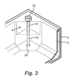
- Figures 1-3 show a transparent perspective view of different examples of a lifting element (4) for a manhole cover (1) from the prior art.
- FIG. 4 diagrammatically shows a bird's-eye view of a manhole cover (1) according to a preferred embodiment of the invention.
- This manhole cover (1) comprises a first (2) and a second bowl (3), wherein the second bowl (3) is suitable to be inserted into the first bowl (2).
- the second bowl (3) has lifting elements (4) at the four corners on the inside of the second bowl (3). They have a straight-prismatic shape with a triangular upper surface. They are provided with a bore (5) which is sealed by a magnetically sensitive sealing element (6).
- These lifting elements (4) do not extend across the entire height of the second or inner bowl (3).
- FIG. 5 shows a bird's-eye view of a manhole cover (1) according to a preferred embodiment of the invention.
- This manhole cover (1) again comprises a first (2) and a second bowl (3) which is suitable to be inserted into the first bowl (2).
- the lifting elements (4) in the four corners of the second bowl (3) again have a straight-prismatic shape with a triangular upper surface. They are provided with a deepening (7) comprising a bore (5) which is sealed by a magnetically sensitive sealing element (6). In this case, these lifting elements (4) do extend across the entire height of the inner bowl (3).
- FIG 6 shows a transparent bird's-eye view of a lifting element (4) of the manhole cover (1) from Figure 5 .
- the lifting element (4) comprises a bore (5) having a deepening (17) on the upper side, which can accommodate the head of the magnetically sensitive sealing element (6).
- This head is provided with an eye (10) which is suitable to be used to enable a lifting means to engage with the sealing element (6).
- the sealing element (6) is also a lifting instrument (9) as the bottom end thereof is provided with a safeguard or stop (11) which provides grip on the lifting element (4) when lifting this lifting instrument (9) and thus makes it possible to lift the second or inner bowl (3) out of the first or outer bowl (2).
- a bore (5) with screw thread (8) in a lifting element (4) in a manhole cover (1) is typically sealed by a screwed-in bolt (see Figure 1 ). If the inner bowl (3) is to be lifted from the outer bowl (2), this bolt (15) is first unscrewed and removed, so that a T-shaped key with screw thread (8) can then be screwed into the bore (5).
- Figure 2 shows such a screwed-in T-key (14) in a lifting element (4) in a manhole cover (1) from the prior art. By means of this key, the inner bowl (3) can be lifted out of the outer bowl (2).
- FIG 7 shows a transparent bird's-eye view of a lifting element (4) for a manhole cover (1) according to a preferred embodiment of the invention.
- the lifting element (4) is provided in the corner of the inner bowl (3) which rests on the outer bowl (2).
- the lifting element (4) comprises a bore (5) with screw thread (8), without a sealing bolt (15). This prevents contact with the screw thread and thus also contact corrosion.
- the screw thread (8) may be used to screw in a lifting instrument.
- the lifting element (4) does not extend across the full height of the inner bowl.
- a magnetically sensitive triangular plate (6) is beared on the upper side, in a deepening (7) of the lifting element (4).
- the plate (6) seals the upper side of the lifting element (4) and thus also the screw thread (8) in the bore (5).
- the sealing plate (6) comprises a blind bore (32) on the underside of the plate which leaves space for incorporating an information-bearing colour code.
- FIG 8 shows a transparent bird's-eye view of a lifting element (4) for a manhole cover (1) according to a preferred embodiment of the invention.
- the lifting element (4) comprises a bore (5) with screw thread (8) without a screwed-in bolt (15).
- a magnetically sensitive triangular plate (6) is beared. Omitting a screwed-in bolt (15) reduces the risk of contact corrosion between bolt (15) and screw thread (8).
- the lifting element (4) does not extend across the entire height of the inner bowl.
- the lifting element (4) is provided with a sealing cap (31) provided in the opening of the bore (5) of the lifting element (4).
- the colour of this sealing cap (31) corresponds to an information-bearing code.
- FIG 9 shows a transparent bird's-eye view of a lifting element (4) for a manhole cover (1) according to a preferred embodiment of the invention.
- the lifting element (4) comprises a bore (5) with screw thread (8).
- the lifting element (4) does not extend across the full height of the inner bowl.
- the bore (5) contains a magnetically sensitive bolt (15) without screw thread (8).
- the bore (5) is sealed by the cylindrical head of this bolt (15).
- the diameter of the foot of this sealing element is smaller than the diameter of the screw thread opening for the lifting instrument.
- the lifting element (4) is provided with a ring (30) underneath the head of the bolt (15).
- the colour of this ring (30) corresponds to an information-bearing code.
- the inner bowl (3) is typically anchored in the outer bowl (2) by means of an anchoring bolt (12) (see Figure 3 ).
- this anchoring bolt (12) is provided with a screw thread (8). Due to the fact that an opening (13) is provided in the inner bowl (3) and a screw thread anchoring (16) is provided in the outer bowl (2), the anchoring bolt (12) can be screwed into the screw thread anchoring or rivet (16) in order thus to anchor the inner bowl (3) in the outer bowl (2).
- an opening (13) may be used to provide access to the interior of the lifting element (4).
- an engagement member is provided in corner elements which is intended to allow engagement of a lifting member in order to lift a second bowl out of a first bowl by means of the lifting member.
- the engagement member comprises a screw thread which can accommodate the engagement member in the corner element.
- Figure 10 shows a transparent bird's-eye view of a lifting element (4) for a manhole cover (1) according to a preferred embodiment of the invention.
- the lifting element (4) comprises a bore (5) without screw thread (8).
- the lifting element (4) extends across the full height of the inner bowl (3).
- a magnetically sensitive sealing element (6) is beared in the bore (5) and has an eye (10) in its head.
- the sealing element (6) is also a lifting instrument (9) due to the fact that the bottom end thereof is provided with a safeguard or stop (11) which provides grip on the lifting element (4) when lifting this lifting instrument (9) and thus makes it possible to lift the inner bowl (3) out of the outer bowl (2).
- the diameter of this safeguard (11) is larger than that of the opening of the lifting element (4).
- this sealing element and lifting element (4) do not comprise any screw thread and there is consequently no contact between a bolt and a screw thread, the risk of contact corrosion is drastically reduced compared to the prior art.
- the diameter of the cylindrical central part of the lifting instrument (9) is smaller than the diameter of the bore (5), thus preventing possible contact between the two here as well.
- the inner bowl (3) is provided with an opening (13) at the bottom of the lifting element (4), as is the case in Figure 3 .
- the presence of an opening in the inner bowl provides access to the lifting element via the underside.
- the opening (13) in the inner bowl (3) is sealed by a removable cap (18).
- the diameter of this opening (13) may be smaller than the foot of the integrated lifting instrument (9), as a result of which the end user can perform cleaning or maintenance operations on the lifting element (4) via this opening at the bottom.
- the diameter of this opening may also be larger than the foot of the integrated lifting element (9), as a result of which the end user can remove the integrated lifting instrument in order to clean and/or replace the latter.
- the foot of the integrated lifting instrument (9) can rest on a removable plastic cap (18) or simply on the outer bowl (2).
- FIG 11 shows a transparent bird's-eye view of a lifting element (4) for a manhole cover (1) according to a preferred embodiment of the invention.
- the lifting element (4) comprises a bore (5) without screw thread (8).
- the lifting element (4) extends across the entire height of the inner bowl (3).
- the bore (5) contains a magnetically sensitive sealing element (6), the head of which is provided with an eye (10).
- the sealing element (6) is also a lifting instrument (9) due to the fact that the bottom end thereof is provided with a safeguard or stop (11) which provides grip on the lifting element (4) when lifting this lifting instrument (9) in order thus to lift the inner bowl (3) out of the outer bowl (2).
- An opening (13) is provided in the side wall of the inner bowl (3). This makes it possible to provide access to the interior of the lifting element (4).
- the lifting element (4) is provided with a ring (30) underneath the head of the lifting instrument (9).
- the colour of the ring (30) corresponds to an information-bearing code.
- Figure 12 shows a cross-sectional bird's-eye view in perspective of a manhole cover (1) provided with lifting elements (4), a plate (41) and a grate (40).
- the lifting elements (4) comprise a bore (5) without screw thread (8).
- the bore (5) contains a magnetically sensitive sealing element (6), the head of which is provided with an eye (10) and the bottom end of which is provided with a safeguard (11).
- An opening (13) is provided in the side wall of the inner bowl (3). This makes it possible to provide access to the interior of the lifting element (4).
- Figure 13 shows a cross-sectional view of the profiles of the first (2) and second bowl (3), as illustrated in Figure 12 .
- the upper side of the profile of the second bowl (3) is provided with a widened section (53) which can rest on a widened section (54) of the first bowl (2).
- the second bowl (3) rests on the profile of the first bowl (2).
- the widened section (53) which also seals the space between the first (2) and second bowl (3), comprises a deepening (50).
- the latter acts as a 'trompe l'oeil'.
- the combination of the upper layer of both profiles therefore seems less wide. This combination is less susceptible to scratches.
- the profile of the first bowl (2) is provided with an upright elevation (51).
- This upright elevation (51) makes it possible to place or position the carrier plate (41) in such a manner that the carrier plate (41) does not prevent the subsequent placement of the second bowl (3).
- the thickness of the carrier plate (41) is determined in such a way that it supports the base plate of the inner bowl.
- This base plate (not shown in the figure) is provided in the groove underneath the projection (52).
- the carrier plate (41) is made from a corrosion-proof material, preferably stainless steel, and increases the load capacity of the cover (1).
- a grip is provided in this carrier plate (41) for the user.
- a grate or reinforcement net (40) may be provided in the second bowl (3).
- a cover which is composed of a first (2) and second bowl (3) and carrier plate (41) is lifted in 2 stages.
- the upright elevation in the profile facilitates positioning of the carrier plate.
- FIG 14A shows a cross-sectional view of a plate (60) provided with a lifting element (4).
- the lifting element (4) comprises a bore (5) in said plate (60) and a sealing element (6), which is beared in said bore (5), which comprises a widened section on the upper side of the plate (60).
- This widened section makes it possible for the sealing element (6) to be anchored in this bore (5) at the head by means of a widened section.
- the lifting element (4) is provided in the centre of the plate (60).
- the head of the sealing element (6) is provided with an eye (10) and is also a lifting instrument (9) due to the fact that the bottom end is provided with a safeguard (11).
- this safeguard (11) comes into contact with the underside of the plate (60), which bore has a smaller diameter and as a result of which the sealing element (6) can be used to lift the plate (60).
- Figure 14A shows a cross-sectional view of the plate (60) wherein the sealing element (6) has been displaced linearly by means of a magnet, resulting in the eye becoming accessible for, for example, a snap hook which lifts the plate upwards by means of the lifting element (4).
- FIG 15 shows a cross-sectional view of a plate (60) provided with a lifting element (4).
- the lifting element (4) comprises a cylindrical jacket on the upper side, which bears against a bore in said plate (60), in which a sealing element (6) is beared.
- the head of the sealing element (6) is provided with an eye (10) and also serves as a lifting instrument (9) due to the fact that the bottom end is provided with a safeguard (11).
- this safeguard (11) comes into contact with the constriction in the lifting element (4) which has a smaller diameter and as a result of which the sealing element (6) can lift the plate (60).
- the lifting element (4) is provided with a support plate (64) which extends on the underside of said plate (60).
- This support plate (64) is preferably attached to the plate (60) by means of glue and/or screws. As a result thereof, said plate (60) is more efficiently supported during lifting.
- the lifting element (4) is provided with a screw-on sealing element (63) which can be used to hermetically seal the lifting element (4) on the underside of the second bowl (3).
- the lifting element (4) is also provided with a screw thread (62) to this end.
- the lifting element (4) may be provided with a taller jacket (61) which can then, for example, be sawn off to the desired height, depending on the plate thickness.
- Figure 16 shows a cross-sectional view of a plate (60) provided with a lifting element (4).
- the lifting element (4) is similar to the lifting element (4) from Example 10, except for a narrowing of the cylindrical jacket (61) on the upper side. In case the thickness of the plate is known, the desired height can be set at the beginning. This narrowing in the jacket (61) makes it possible for the sealing element (6) to be anchored therein by means of a widened section at the head. During removal of the sealing element (6), this safeguard (11) comes into contact with the constriction in the lifting element (4) which has a smaller diameter, as a result of which the sealing element (6) can lift the plate (60).
- Figure 17 shows a cross-sectional view of a plate (60) provided with a lifting element (4).
- the lifting element (4) comprises a cylindrical jacket (61) on the upper side which bears against a bore in said plate (60) in which a sealing element (6) is beared.
- the bore in the plate (60) comprises a widened section on the upper side of the plate (60).
- This widened section makes it possible for the lifting element (4) to be anchored in the bore of the plate by means of a widened section (67) on the cylindrical jacket (61).
- the lifting element (4) is provided in the centre of the plate (60).
- the sealing element (6) is provided with an eye (10) in its head and also serves as a lifting instrument (9) due to the fact that the bottom end is provided with a safeguard (11).
- the lifting element (4) is provided with screw thread (62) via which a sealing element (63), which is likewise provided with screw thread (62), can be screwed on, which sealing element (63) can hermetically seal the lifting element (4) on the underside of the second bowl (3).
- the sealing element (63) itself is provided with a support plate (64) which extends on the underside of said plate (60). As a result of the widened section (67) and therefore the anchoring of the lifting element (4) on the upper side, the support plate (64) is suitable to be clamped against the plate (60) by screwing on the lifting element (4) via the screw thread (62).
- Figure 18 shows a cross-sectional bird's-eye view of a plate provided with a lifting elem ent.
- the lifting element (4) in the centre of the plate (60) comprises a cylindrical jacket (61) which bears against a bore in the plate (60) in which a sealing element (6) is beared, the head of which is provided with an eye (10) and the bottom end of which is provided with a safeguard (11).
- this lifting element (4) makes it possible to set the desired height of the cylindrical jacket (61) by means of screwing on or unscrewing this jacket (61) via the inner screw thread (66) of the supporting element (64).
- the cylindrical jacket (61) comprises a screw thread (66) via which it is coupled to the supporting element (64) which comprises a corresponding screw thread (66) on the inner side.
- the supporting element (64) comprises a support plate which extends on the underside of said plate (60). This also comprises a cylindrical jacket and is also provided with a screw thread (62) on the outer side and is attached to the underside of the plate (60) by means of glue and/or screws.
- a sealing element (63) with a corresponding screw thread (62) on the inner side can be screwed onto the lifting element (4), which sealing element (63) is suitable to be used to hermetically seal the lifting element (4) on the underside of the second bowl (3).
- Placement of the lifting element (4) is preferably carried out as follows. First, the supporting element (64) is attached to the underside of the plate (60). Subsequently, the element with the cylindrical jacket (61) is screwed into the supporting element (64) until the height of this element (61) approximately reaches the upper surface of the plate (60). Then, the sealing element (6) is placed in element (61) from above and the nut or safeguard (11) is then screwed onto the sealing element (6) on the underside. Finally, the sealing element (63) is screwed onto the lifting element (4) via the outer screw thread (62) of element (64) in order to hermetically seal the underside thereof.
- Figure 19 shows a perspective view of a sealing element (6).
- a sealing element (6) corresponds to a bolt without screw thread. It is suitable to be fitted in the bore (5) of the manhole cover from the prior art, as is illustrated in Figures 1 and 2 .
- the sealing element (6) thus seals the bore (5) and the screw thread (8) of the manhole cover.
Landscapes
- Engineering & Computer Science (AREA)
- Environmental & Geological Engineering (AREA)
- Life Sciences & Earth Sciences (AREA)
- General Life Sciences & Earth Sciences (AREA)
- Mining & Mineral Resources (AREA)
- Paleontology (AREA)
- Civil Engineering (AREA)
- General Engineering & Computer Science (AREA)
- Structural Engineering (AREA)
- Underground Structures, Protecting, Testing And Restoring Foundations (AREA)
- Catching Or Destruction (AREA)
Applications Claiming Priority (1)
| Application Number | Priority Date | Filing Date | Title |
|---|---|---|---|
| BE201200829A BE1020642A5 (nl) | 2012-12-10 | 2012-12-10 | Inrichting voor een gronddeksel, tilelement en werkwijze voor het tillen hiervan. |
Publications (4)
| Publication Number | Publication Date |
|---|---|
| EP2740848A2 true EP2740848A2 (de) | 2014-06-11 |
| EP2740848A3 EP2740848A3 (de) | 2017-03-15 |
| EP2740848C0 EP2740848C0 (de) | 2025-07-16 |
| EP2740848B1 EP2740848B1 (de) | 2025-07-16 |
Family
ID=47631139
Family Applications (1)
| Application Number | Title | Priority Date | Filing Date |
|---|---|---|---|
| EP13196546.9A Active EP2740848B1 (de) | 2012-12-10 | 2013-12-10 | Kanaldeckelplatte, Hebeelement und Dichtelement für Kanaldeckelplatten |
Country Status (4)
| Country | Link |
|---|---|
| EP (1) | EP2740848B1 (de) |
| BE (1) | BE1020642A5 (de) |
| ES (1) | ES3039618T3 (de) |
| PL (1) | PL2740848T3 (de) |
Cited By (1)
| Publication number | Priority date | Publication date | Assignee | Title |
|---|---|---|---|---|
| CN110306588A (zh) * | 2019-07-11 | 2019-10-08 | 中南大学 | 一种用于加筋土挡墙的面板模块单元及加筋土挡墙 |
Citations (2)
| Publication number | Priority date | Publication date | Assignee | Title |
|---|---|---|---|---|
| EP1705295A2 (de) | 2005-02-11 | 2006-09-27 | D.V.S. Eurometaal | Profil einer Abdeckung |
| WO2010134046A1 (en) | 2009-05-20 | 2010-11-25 | De Vroe D.V.S. Metaal | Brick cover and assembly of brick cover and lifting member |
Family Cites Families (6)
| Publication number | Priority date | Publication date | Assignee | Title |
|---|---|---|---|---|
| DE7931057U1 (de) * | 1979-11-02 | 1980-02-14 | Passavant-Werke Michelbacher Huette, 6209 Aarbergen | Vorreiberverschluss fuer schachtdeckel, roste o.dgl. |
| GB2175630A (en) * | 1985-05-28 | 1986-12-03 | Jones & Son Frederick | Locking and/or lifting means for a manhole cover |
| DE29802438U1 (de) * | 1998-02-12 | 1998-05-20 | Pilz-Scriba, Tobias, Dipl.-Kaufm., 82065 Baierbrunn | Schachtabdeckung |
| JP3655265B2 (ja) * | 2002-07-15 | 2005-06-02 | タキゲン製造株式会社 | マンホール蓋用施錠装置 |
| JP3640942B2 (ja) * | 2002-08-19 | 2005-04-20 | タキゲン製造株式会社 | マンホール蓋用施錠装置 |
| US7712515B2 (en) * | 2006-04-10 | 2010-05-11 | East Jordan Iron Works, Inc. | Municipal casting frame and method of manufacturing same |
-
2012
- 2012-12-10 BE BE201200829A patent/BE1020642A5/nl active
-
2013
- 2013-12-10 ES ES13196546T patent/ES3039618T3/es active Active
- 2013-12-10 EP EP13196546.9A patent/EP2740848B1/de active Active
- 2013-12-10 PL PL13196546.9T patent/PL2740848T3/pl unknown
Patent Citations (2)
| Publication number | Priority date | Publication date | Assignee | Title |
|---|---|---|---|---|
| EP1705295A2 (de) | 2005-02-11 | 2006-09-27 | D.V.S. Eurometaal | Profil einer Abdeckung |
| WO2010134046A1 (en) | 2009-05-20 | 2010-11-25 | De Vroe D.V.S. Metaal | Brick cover and assembly of brick cover and lifting member |
Cited By (2)
| Publication number | Priority date | Publication date | Assignee | Title |
|---|---|---|---|---|
| CN110306588A (zh) * | 2019-07-11 | 2019-10-08 | 中南大学 | 一种用于加筋土挡墙的面板模块单元及加筋土挡墙 |
| CN110306588B (zh) * | 2019-07-11 | 2023-12-08 | 中南大学 | 一种用于加筋土挡墙的面板模块单元及加筋土挡墙 |
Also Published As
| Publication number | Publication date |
|---|---|
| EP2740848C0 (de) | 2025-07-16 |
| ES3039618T3 (en) | 2025-10-23 |
| PL2740848T3 (pl) | 2025-11-24 |
| EP2740848B1 (de) | 2025-07-16 |
| BE1020642A5 (nl) | 2014-02-04 |
| EP2740848A3 (de) | 2017-03-15 |
Similar Documents
| Publication | Publication Date | Title |
|---|---|---|
| KR101377009B1 (ko) | 높이 및 경사 조절이 가능한 맨홀 뚜껑 | |
| US7862729B2 (en) | Deck drain cover | |
| MXPA03006406A (es) | Cubierta para una construccion de concreto. | |
| US5623792A (en) | Grave marker leveling | |
| EP3012375A1 (de) | Verfahren zur herstellung eines mannlochs | |
| KR101205610B1 (ko) | 그레이팅 잠금장치 및 방법 | |
| WO2007116375A2 (en) | Municipal casting frame and method of manufacturing same | |
| KR101114840B1 (ko) | 보강 지주조립체 | |
| KR100949575B1 (ko) | 높이 조절이 가능한 맨홀덮개장치 | |
| EP2740848B1 (de) | Kanaldeckelplatte, Hebeelement und Dichtelement für Kanaldeckelplatten | |
| EP3394346B1 (de) | Adapter | |
| US20090321442A1 (en) | Utility cover having a bowl cavity and a removable lid | |
| US7322549B2 (en) | Refuse container retainer | |
| CN203866860U (zh) | 防坠井 | |
| US7452158B1 (en) | Infill for bollard footing hole | |
| KR101618797B1 (ko) | 해양 콘크리트구조물의 인양보조장치 및 그를 이용한 인양방법 | |
| KR101313818B1 (ko) | 휀스용 지주 고정구 | |
| JP2006118159A (ja) | ポール装置 | |
| AU2009101231A4 (en) | Side Pit Entry Cover | |
| KR100561748B1 (ko) | 토목 및 도로 교통 시설물 설치용 기둥의 매설형 하부 기초 | |
| CN222648861U (zh) | 一种市政建设用组合式井盖 | |
| BE1018760A3 (nl) | Klinkerdeksel en samenstel van een klinkerdeksel en een optilorgaan. | |
| KR200313313Y1 (ko) | 토목 및 도로 교통 시설물 설치용 기둥의 매설형 하부 기초 | |
| JP3100419U (ja) | 境界ブロック着脱型暗渠ブロック | |
| AU2014101450A4 (en) | Improvements in access covers and frames |
Legal Events
| Date | Code | Title | Description |
|---|---|---|---|
| PUAI | Public reference made under article 153(3) epc to a published international application that has entered the european phase |
Free format text: ORIGINAL CODE: 0009012 |
|
| 17P | Request for examination filed |
Effective date: 20131210 |
|
| AK | Designated contracting states |
Kind code of ref document: A2 Designated state(s): AL AT BE BG CH CY CZ DE DK EE ES FI FR GB GR HR HU IE IS IT LI LT LU LV MC MK MT NL NO PL PT RO RS SE SI SK SM TR |
|
| AX | Request for extension of the european patent |
Extension state: BA ME |
|
| RIN1 | Information on inventor provided before grant (corrected) |
Inventor name: LECLERCQ, GEERT |
|
| RAP1 | Party data changed (applicant data changed or rights of an application transferred) |
Owner name: DE VROE PROJECTEN NV |
|
| RAP1 | Party data changed (applicant data changed or rights of an application transferred) |
Owner name: DE VROE GROEP |
|
| RAP1 | Party data changed (applicant data changed or rights of an application transferred) |
Owner name: YUCON SOLUTIONS BVBA |
|
| PUAL | Search report despatched |
Free format text: ORIGINAL CODE: 0009013 |
|
| AK | Designated contracting states |
Kind code of ref document: A3 Designated state(s): AL AT BE BG CH CY CZ DE DK EE ES FI FR GB GR HR HU IE IS IT LI LT LU LV MC MK MT NL NO PL PT RO RS SE SI SK SM TR |
|
| AX | Request for extension of the european patent |
Extension state: BA ME |
|
| RIC1 | Information provided on ipc code assigned before grant |
Ipc: E02D 29/14 20060101AFI20170207BHEP |
|
| STAA | Information on the status of an ep patent application or granted ep patent |
Free format text: STATUS: REQUEST FOR EXAMINATION WAS MADE |
|
| R17P | Request for examination filed (corrected) |
Effective date: 20170915 |
|
| RBV | Designated contracting states (corrected) |
Designated state(s): AL AT BE BG CH CY CZ DE DK EE ES FI FR GB GR HR HU IE IS IT LI LT LU LV MC MK MT NL NO PL PT RO RS SE SI SK SM TR |
|
| STAA | Information on the status of an ep patent application or granted ep patent |
Free format text: STATUS: EXAMINATION IS IN PROGRESS |
|
| 17Q | First examination report despatched |
Effective date: 20180115 |
|
| GRAP | Despatch of communication of intention to grant a patent |
Free format text: ORIGINAL CODE: EPIDOSNIGR1 |
|
| STAA | Information on the status of an ep patent application or granted ep patent |
Free format text: STATUS: GRANT OF PATENT IS INTENDED |
|
| INTG | Intention to grant announced |
Effective date: 20250205 |
|
| GRAS | Grant fee paid |
Free format text: ORIGINAL CODE: EPIDOSNIGR3 |
|
| GRAA | (expected) grant |
Free format text: ORIGINAL CODE: 0009210 |
|
| STAA | Information on the status of an ep patent application or granted ep patent |
Free format text: STATUS: THE PATENT HAS BEEN GRANTED |
|
| AK | Designated contracting states |
Kind code of ref document: B1 Designated state(s): AL AT BE BG CH CY CZ DE DK EE ES FI FR GB GR HR HU IE IS IT LI LT LU LV MC MK MT NL NO PL PT RO RS SE SI SK SM TR |
|
| REG | Reference to a national code |
Ref country code: GB Ref legal event code: FG4D |
|
| REG | Reference to a national code |
Ref country code: CH Ref legal event code: EP Ref country code: DE Ref legal event code: R096 Ref document number: 602013086890 Country of ref document: DE |
|
| REG | Reference to a national code |
Ref country code: IE Ref legal event code: FG4D |
|
| U01 | Request for unitary effect filed |
Effective date: 20250808 |
|
| U07 | Unitary effect registered |
Designated state(s): AT BE BG DE DK EE FI FR IT LT LU LV MT NL PT RO SE SI Effective date: 20250820 |
|
| REG | Reference to a national code |
Ref country code: ES Ref legal event code: FG2A Ref document number: 3039618 Country of ref document: ES Kind code of ref document: T3 Effective date: 20251023 |
|
| REG | Reference to a national code |
Ref country code: CH Ref legal event code: U11 Free format text: ST27 STATUS EVENT CODE: U-0-0-U10-U11 (AS PROVIDED BY THE NATIONAL OFFICE) Effective date: 20260101 |
|
| PG25 | Lapsed in a contracting state [announced via postgrant information from national office to epo] |
Ref country code: IS Free format text: LAPSE BECAUSE OF FAILURE TO SUBMIT A TRANSLATION OF THE DESCRIPTION OR TO PAY THE FEE WITHIN THE PRESCRIBED TIME-LIMIT Effective date: 20251116 |
|
| PGFP | Annual fee paid to national office [announced via postgrant information from national office to epo] |
Ref country code: GB Payment date: 20251219 Year of fee payment: 13 |
|
| PG25 | Lapsed in a contracting state [announced via postgrant information from national office to epo] |
Ref country code: HR Free format text: LAPSE BECAUSE OF FAILURE TO SUBMIT A TRANSLATION OF THE DESCRIPTION OR TO PAY THE FEE WITHIN THE PRESCRIBED TIME-LIMIT Effective date: 20250716 |
|
| PG25 | Lapsed in a contracting state [announced via postgrant information from national office to epo] |
Ref country code: GR Free format text: LAPSE BECAUSE OF FAILURE TO SUBMIT A TRANSLATION OF THE DESCRIPTION OR TO PAY THE FEE WITHIN THE PRESCRIBED TIME-LIMIT Effective date: 20251017 |
|
| PGFP | Annual fee paid to national office [announced via postgrant information from national office to epo] |
Ref country code: IE Payment date: 20251219 Year of fee payment: 13 |
|
| PGFP | Annual fee paid to national office [announced via postgrant information from national office to epo] |
Ref country code: PL Payment date: 20251128 Year of fee payment: 13 |
|
| PG25 | Lapsed in a contracting state [announced via postgrant information from national office to epo] |
Ref country code: RS Free format text: LAPSE BECAUSE OF FAILURE TO SUBMIT A TRANSLATION OF THE DESCRIPTION OR TO PAY THE FEE WITHIN THE PRESCRIBED TIME-LIMIT Effective date: 20251016 |
|
| U20 | Renewal fee for the european patent with unitary effect paid |
Year of fee payment: 13 Effective date: 20251230 |
|
| PG25 | Lapsed in a contracting state [announced via postgrant information from national office to epo] |
Ref country code: SM Free format text: LAPSE BECAUSE OF FAILURE TO SUBMIT A TRANSLATION OF THE DESCRIPTION OR TO PAY THE FEE WITHIN THE PRESCRIBED TIME-LIMIT Effective date: 20250716 |
|
| PGFP | Annual fee paid to national office [announced via postgrant information from national office to epo] |
Ref country code: ES Payment date: 20260130 Year of fee payment: 13 |
|
| PGFP | Annual fee paid to national office [announced via postgrant information from national office to epo] |
Ref country code: NO Payment date: 20251230 Year of fee payment: 13 |
|
| PG25 | Lapsed in a contracting state [announced via postgrant information from national office to epo] |
Ref country code: CZ Free format text: LAPSE BECAUSE OF FAILURE TO SUBMIT A TRANSLATION OF THE DESCRIPTION OR TO PAY THE FEE WITHIN THE PRESCRIBED TIME-LIMIT Effective date: 20250716 |
|
| PGFP | Annual fee paid to national office [announced via postgrant information from national office to epo] |
Ref country code: CH Payment date: 20260101 Year of fee payment: 13 |
|
| PG25 | Lapsed in a contracting state [announced via postgrant information from national office to epo] |
Ref country code: SK Free format text: LAPSE BECAUSE OF FAILURE TO SUBMIT A TRANSLATION OF THE DESCRIPTION OR TO PAY THE FEE WITHIN THE PRESCRIBED TIME-LIMIT Effective date: 20250716 |
|
| PLBE | No opposition filed within time limit |
Free format text: ORIGINAL CODE: 0009261 |
|
| STAA | Information on the status of an ep patent application or granted ep patent |
Free format text: STATUS: NO OPPOSITION FILED WITHIN TIME LIMIT |
|
| REG | Reference to a national code |
Ref country code: CH Ref legal event code: L10 Free format text: ST27 STATUS EVENT CODE: U-0-0-L10-L00 (AS PROVIDED BY THE NATIONAL OFFICE) Effective date: 20260528 |
|
| 26N | No opposition filed |
Effective date: 20260417 |
|
| PG25 | Lapsed in a contracting state [announced via postgrant information from national office to epo] |
Ref country code: MC Free format text: LAPSE BECAUSE OF FAILURE TO SUBMIT A TRANSLATION OF THE DESCRIPTION OR TO PAY THE FEE WITHIN THE PRESCRIBED TIME-LIMIT Effective date: 20250716 |