EP2741105A2 - Pièce de carrosserie - Google Patents
Pièce de carrosserie Download PDFInfo
- Publication number
- EP2741105A2 EP2741105A2 EP13193168.5A EP13193168A EP2741105A2 EP 2741105 A2 EP2741105 A2 EP 2741105A2 EP 13193168 A EP13193168 A EP 13193168A EP 2741105 A2 EP2741105 A2 EP 2741105A2
- Authority
- EP
- European Patent Office
- Prior art keywords
- layer
- body part
- electrically conductive
- heating
- frame
- Prior art date
- Legal status (The legal status is an assumption and is not a legal conclusion. Google has not performed a legal analysis and makes no representation as to the accuracy of the status listed.)
- Withdrawn
Links
- 238000010438 heat treatment Methods 0.000 claims abstract description 47
- 239000010410 layer Substances 0.000 claims description 65
- 239000008186 active pharmaceutical agent Substances 0.000 claims description 10
- 239000002245 particle Substances 0.000 claims description 5
- 239000011888 foil Substances 0.000 claims description 4
- 239000011241 protective layer Substances 0.000 claims description 4
- 238000002788 crimping Methods 0.000 claims description 3
- 238000004049 embossing Methods 0.000 claims description 3
- 239000007788 liquid Substances 0.000 claims description 2
- 239000012790 adhesive layer Substances 0.000 claims 1
- 235000011837 pasties Nutrition 0.000 claims 1
- 239000000126 substance Substances 0.000 claims 1
- 238000011161 development Methods 0.000 description 3
- 230000018109 developmental process Effects 0.000 description 3
- OKTJSMMVPCPJKN-UHFFFAOYSA-N Carbon Chemical compound [C] OKTJSMMVPCPJKN-UHFFFAOYSA-N 0.000 description 2
- 239000011248 coating agent Substances 0.000 description 2
- 238000000576 coating method Methods 0.000 description 2
- 239000004020 conductor Substances 0.000 description 2
- 239000003973 paint Substances 0.000 description 2
- 230000005855 radiation Effects 0.000 description 2
- 150000003839 salts Chemical class 0.000 description 2
- 238000007792 addition Methods 0.000 description 1
- 230000005540 biological transmission Effects 0.000 description 1
- 229910052799 carbon Inorganic materials 0.000 description 1
- 239000002041 carbon nanotube Substances 0.000 description 1
- 229910021393 carbon nanotube Inorganic materials 0.000 description 1
- 230000001419 dependent effect Effects 0.000 description 1
- 239000000428 dust Substances 0.000 description 1
- 230000000694 effects Effects 0.000 description 1
- 230000007613 environmental effect Effects 0.000 description 1
- 239000000463 material Substances 0.000 description 1
- 238000005259 measurement Methods 0.000 description 1
- 239000002071 nanotube Substances 0.000 description 1
- 230000000149 penetrating effect Effects 0.000 description 1
- 230000035515 penetration Effects 0.000 description 1
- 238000009877 rendering Methods 0.000 description 1
- 230000000284 resting effect Effects 0.000 description 1
- 238000007650 screen-printing Methods 0.000 description 1
- 238000007789 sealing Methods 0.000 description 1
- XLYOFNOQVPJJNP-UHFFFAOYSA-N water Substances O XLYOFNOQVPJJNP-UHFFFAOYSA-N 0.000 description 1
Images


Classifications
-
- G—PHYSICS
- G01—MEASURING; TESTING
- G01S—RADIO DIRECTION-FINDING; RADIO NAVIGATION; DETERMINING DISTANCE OR VELOCITY BY USE OF RADIO WAVES; LOCATING OR PRESENCE-DETECTING BY USE OF THE REFLECTION OR RERADIATION OF RADIO WAVES; ANALOGOUS ARRANGEMENTS USING OTHER WAVES
- G01S13/00—Systems using the reflection or reradiation of radio waves, e.g. radar systems; Analogous systems using reflection or reradiation of waves whose nature or wavelength is irrelevant or unspecified
- G01S13/88—Radar or analogous systems specially adapted for specific applications
- G01S13/93—Radar or analogous systems specially adapted for specific applications for anti-collision purposes
- G01S13/931—Radar or analogous systems specially adapted for specific applications for anti-collision purposes of land vehicles
-
- G—PHYSICS
- G01—MEASURING; TESTING
- G01S—RADIO DIRECTION-FINDING; RADIO NAVIGATION; DETERMINING DISTANCE OR VELOCITY BY USE OF RADIO WAVES; LOCATING OR PRESENCE-DETECTING BY USE OF THE REFLECTION OR RERADIATION OF RADIO WAVES; ANALOGOUS ARRANGEMENTS USING OTHER WAVES
- G01S7/00—Details of systems according to groups G01S13/00, G01S15/00, G01S17/00
- G01S7/02—Details of systems according to groups G01S13/00, G01S15/00, G01S17/00 of systems according to group G01S13/00
- G01S7/03—Details of HF subsystems specially adapted therefor, e.g. common to transmitter and receiver
-
- G—PHYSICS
- G01—MEASURING; TESTING
- G01S—RADIO DIRECTION-FINDING; RADIO NAVIGATION; DETERMINING DISTANCE OR VELOCITY BY USE OF RADIO WAVES; LOCATING OR PRESENCE-DETECTING BY USE OF THE REFLECTION OR RERADIATION OF RADIO WAVES; ANALOGOUS ARRANGEMENTS USING OTHER WAVES
- G01S13/00—Systems using the reflection or reradiation of radio waves, e.g. radar systems; Analogous systems using reflection or reradiation of waves whose nature or wavelength is irrelevant or unspecified
- G01S13/88—Radar or analogous systems specially adapted for specific applications
- G01S13/93—Radar or analogous systems specially adapted for specific applications for anti-collision purposes
- G01S13/931—Radar or analogous systems specially adapted for specific applications for anti-collision purposes of land vehicles
- G01S2013/9327—Sensor installation details
- G01S2013/93275—Sensor installation details in the bumper area
-
- G—PHYSICS
- G01—MEASURING; TESTING
- G01S—RADIO DIRECTION-FINDING; RADIO NAVIGATION; DETERMINING DISTANCE OR VELOCITY BY USE OF RADIO WAVES; LOCATING OR PRESENCE-DETECTING BY USE OF THE REFLECTION OR RERADIATION OF RADIO WAVES; ANALOGOUS ARRANGEMENTS USING OTHER WAVES
- G01S7/00—Details of systems according to groups G01S13/00, G01S15/00, G01S17/00
- G01S7/02—Details of systems according to groups G01S13/00, G01S15/00, G01S17/00 of systems according to group G01S13/00
- G01S7/027—Constructional details of housings, e.g. form, type, material or ruggedness
-
- G—PHYSICS
- G01—MEASURING; TESTING
- G01S—RADIO DIRECTION-FINDING; RADIO NAVIGATION; DETERMINING DISTANCE OR VELOCITY BY USE OF RADIO WAVES; LOCATING OR PRESENCE-DETECTING BY USE OF THE REFLECTION OR RERADIATION OF RADIO WAVES; ANALOGOUS ARRANGEMENTS USING OTHER WAVES
- G01S7/00—Details of systems according to groups G01S13/00, G01S15/00, G01S17/00
- G01S7/02—Details of systems according to groups G01S13/00, G01S15/00, G01S17/00 of systems according to group G01S13/00
- G01S7/40—Means for monitoring or calibrating
- G01S7/4004—Means for monitoring or calibrating of parts of a radar system
- G01S7/4039—Means for monitoring or calibrating of parts of a radar system of sensor or antenna obstruction, e.g. dirt- or ice-coating
- G01S7/4043—Means for monitoring or calibrating of parts of a radar system of sensor or antenna obstruction, e.g. dirt- or ice-coating including means to prevent or remove the obstruction
Definitions
- the invention relates to a body part for a motor vehicle according to the type of claim 1.
- sensors are installed in body parts, which serve, for example, the distance measurement. Such sensors may be installed in a front and / or rear bumper and, during parking, detect the distance to an obstacle, another vehicle. Such systems are known as PDC sensors.
- Known sensors of this type are embedded in apertures of bumpers and painted with one of the color of the vehicle, the bumper.
- An example of a embedded in a body part, a bumper or a bumper PDC sensor shows the DE 103 14 862 A1 ,
- the DE 10 2011 107 216 A1 describes a radome of a transmitting and receiving device for radar waves in a motor vehicle.
- a heating device is arranged flat between a base layer and a cover layer.
- the heating device is designed as an electrically conductive paint.
- the prior art solution provides the transmit and receive active end of the sensor with a heater.
- the sensor is received in an opening of the body part, the bumper and thus visible from the outside.
- the object of the present invention is to provide a body part for a sensor receptacle in relation to the known versions of improved design.
- the invention proposes a body part for a motor vehicle, in particular in the form of a bumper or a bumper, wherein the body part is made of a plastic and has on its back a surface for a rear attachable sensor, preferably a radar sensor, said surface is a heater in Form associated with an electrically conductive layer.
- the area to be heated in a plastic component is realized with two opposing electrodes and a resistance heating element located between the electrodes (surface heating element).
- the resistance heating element, the heating layer consists of a viscous (pourable, pressure, spreadable) reactive liquid which cures in a short time either thermally or with UV action.
- the heating device realized in accordance with the invention - the flat application, the flat layer which is flowed through in the layer thickness and over the surface of current - has the advantage of a much less sensitive design and at the same time a very flat heating effect compared with a heating foil design applied directly to a film or directly.
- the conductive layer of the heating device according to the invention can be applied as a continuous surface, but also in narrow, mutually insulated strips.
- the electrically conductive layer is formed as a conductive particles having, consisting of such particles paint, a viscous paste.
- the resistance of the layer can be determined by additions of carbon in the form of nano-tubes specifically set.
- the layer is preferably spread or applied by screen printing.
- a preferred development of the invention provides a protective layer above the heating layer, thus completely covering it. This will make the heating layer damaging influences, in particular by salt avoided.
- the coating can be applied directly to the plastic component, the back of the plastic bumper.
- the coating, the heating layer can also be applied to a film or between two films.
- the film (s) then act as a sealing layer.
- the energization of the heating layer via two linear electrodes formed which frame the surface of the heating layer opposite each other.
- the connection of the electrode wires is via a plug-in system, which is designed in the form of plug contacts and corresponds to an automotive standard.
- a separate electronic component provides the control of the current intensity, in particular depending on the driving condition and / or the temperature.
- the contacting of the electrodes can be realized via a mounted on the back of the component to be heated frame with integrated / cast-in connector.
- the contacting can be done by crimping or embossing the electrode with electrical lines.
- the contact between frame and electrodes can be realized by integrated, conductive teeth in the frame, which press into the electrode path by pressing the frame onto the electrodes.
- the layer of the heater is embedded in a recess of the plastic component.
- the layer thickness of the component is in this case reduced such that the desired radiation characteristic results, the required transmission and receiving radiation intensity is achieved, the required Abtau nie is achieved.
- the layer thickness of the heating layer is chosen such that on the one hand the required heating power results, on the other hand no Restriction of the sensor function is done.
- the electrically conductive layer of the heating device can also be realized by rendering the plastic electrically conductive in the intended area by adding conductive particles, for example carbon nanotubes.
- a development of the invention provides that the rear side of the body part is thinned in exactly the surface area which corresponds to the top surface of the sensor.
- An embodiment of the invention provides that the sensor is attached by means of a holder on the back of the body part, the bumper.
- the body part, the bumper may have rear locking elements or fastening elements, via which the sensor together with a holder receiving it is attachable.
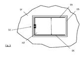
- the FIG. 1 shows in plan view a part of the back of a plastic bumper SF.
- the back of the bumper SF is covered with an electrically conductive layer HZ.
- the electrically conductive layer HZ is provided with two frame-shaped electrodes EK, via which the heating layer is subjected to a voltage.
- the electrodes EK are formed, for example, as thin metallic tracks, conductor tracks which are laid on the heating layer HZ or embedded in the layer HZ and are in good electrical contact therewith.
- the opposite strands of the electrodes EK result in a uniformly penetrating the surface of the heating layer HZ current flow, which is indicated by the double arrow.
- the socket communicates with electronics via which the voltage is applied to the heating layer HZ.
- the heating layer HZ is coated with a covering layer DS acting as a protective layer, which protects the material of the heating layer HZ from environmental influences (dust, water, salt).
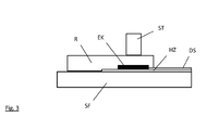
- the FIG. 2 shows a corresponding section through the plastic bumper SF, the heating layer HZ and this covering cover layer DS.
- FIG. 3 shows an embodiment for contacting the plug-in connections of the electrodes EK with a control electronics, not shown.
- a plug SK the outer socket surrounding the plug pins, is mounted on a frame element R.
- the frame R, the frame element engages over the electrodes EK and also parts of the film DS protected by the heating layer HZ.
- the frame element is connected to the body part SF, for example, glued and can in addition to the plug SK also hold the sensor or recording elements (snap-in connections, clips) have for the sensor.
- FIG. 4 a further contacting option is shown.
- the plug SK whose pins are mounted directly on the electrode EK, electrically connected to these.
- the electrodes EK, the corresponding conductor tracks are covered in the edge region by the heating layer HZ and the film DS protecting this heating layer HZ.
- the plug pins of the plug SK are guided in the edge region shown by the heating and the cover layer HZ, DS - these have corresponding openings, passages whose application is recessed in this area.
- the edge of the heating layer HZ is associated with a surface of the heating element at least partially surrounding frame member R, which prevents lateral penetration of dirt or moisture.
- the frame element R is connected to the body part SF, for example. Glued to this. Also in this embodiment, the frame member R receiving, fastening elements for the sensor.
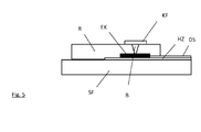
- FIG. 5 shows an embodiment of the contact, in which a crimping, embossing a seated on the top of the frame R contact surface KF with the underlying electrode EK takes place.
- the frame R at least partially surrounds the surface of the heating layer HZ and also covers the electrode EK resting on the heating layer.
- the connected to the body part SF frame R thus forms a lateral termination of the heating surface HZ for the sensor, not shown.
- the contact surface KF which is electrically conductive on the upper side of the frame R, is crimped in a region in such a way that a bridge B passing through the frame body is formed, which connects the contact surface KF electrically to the underlying electrode EK.
- the contact surface KF attached to the frame R has tooth-shaped elements on the side facing the body part, which engage in the heating layer or the electrodes when the frame R is attached, and are thus pressed into contact.
- the teeth are then like those in FIG. 5 formed bridges B formed.
Landscapes
- Engineering & Computer Science (AREA)
- Radar, Positioning & Navigation (AREA)
- Remote Sensing (AREA)
- Physics & Mathematics (AREA)
- Computer Networks & Wireless Communication (AREA)
- General Physics & Mathematics (AREA)
- Electromagnetism (AREA)
- Resistance Heating (AREA)
- Cooling, Air Intake And Gas Exhaust, And Fuel Tank Arrangements In Propulsion Units (AREA)
Applications Claiming Priority (2)
| Application Number | Priority Date | Filing Date | Title |
|---|---|---|---|
| DE102012222557 | 2012-12-07 | ||
| DE102013200364.1A DE102013200364A1 (de) | 2012-12-07 | 2013-01-14 | Karosserieteil |
Publications (2)
| Publication Number | Publication Date |
|---|---|
| EP2741105A2 true EP2741105A2 (fr) | 2014-06-11 |
| EP2741105A3 EP2741105A3 (fr) | 2014-08-13 |
Family
ID=49641521
Family Applications (1)
| Application Number | Title | Priority Date | Filing Date |
|---|---|---|---|
| EP13193168.5A Withdrawn EP2741105A3 (fr) | 2012-12-07 | 2013-11-15 | Pièce de carrosserie |
Country Status (2)
| Country | Link |
|---|---|
| EP (1) | EP2741105A3 (fr) |
| DE (1) | DE102013200364A1 (fr) |
Cited By (6)
| Publication number | Priority date | Publication date | Assignee | Title |
|---|---|---|---|---|
| WO2017042284A1 (fr) * | 2015-09-11 | 2017-03-16 | Commissariat A L'energie Atomique Et Aux Energies Alternatives | Radome equipe d'un systeme resistif chauffant structure en bandes de nano-elements metalliques |
| FR3041104A1 (fr) * | 2015-09-14 | 2017-03-17 | Plastic Omnium Cie | Dispositif chauffant de protection d'un radar de vehicule automobile |
| WO2017055153A1 (fr) * | 2015-09-30 | 2017-04-06 | Hella Kgaa Hueck & Co. | Procédé de fabrication d'un radôme et radôme correspondant |
| WO2020099670A1 (fr) * | 2018-11-16 | 2020-05-22 | Compagnie Plastic Omnium | Pièce extérieure de véhicule automobile multicouche comprenant un élément chauffant |
| EP3772133A1 (fr) * | 2019-07-29 | 2021-02-03 | Compagnie Plastic Omnium SE | Dispositif de protection pour lidar de véhicule automobile |
| CN112690040A (zh) * | 2018-09-21 | 2021-04-20 | 纬湃科技有限责任公司 | 接触装置和具有基板和布置在其上的接触装置的设备 |
Families Citing this family (2)
| Publication number | Priority date | Publication date | Assignee | Title |
|---|---|---|---|---|
| DE102018206290B3 (de) | 2018-04-24 | 2019-06-19 | Audi Ag | Radarsensoreinrichtung für ein Kraftfahrzeug und Kraftfahrzeug |
| WO2025073383A1 (fr) | 2023-10-06 | 2025-04-10 | Volkswagen Aktiengesellschaft | Dispositif électrooptique pour un dispositif de détection, agencement et dispositif de détection |
Citations (2)
| Publication number | Priority date | Publication date | Assignee | Title |
|---|---|---|---|---|
| DE10314862A1 (de) | 2003-04-02 | 2004-10-14 | Bayerische Motoren Werke Ag | Sensoranordnung einer Einparkhilfe |
| DE102011107216A1 (de) | 2011-07-13 | 2012-03-08 | Daimler Ag | Radom für eine Sende- und Empfangseinrichtung von Radarwellen eines Kraftfahrzeugs |
Family Cites Families (3)
| Publication number | Priority date | Publication date | Assignee | Title |
|---|---|---|---|---|
| DE10149337A1 (de) * | 2001-10-06 | 2003-04-17 | Bosch Gmbh Robert | Vorrichtung für ein Frontabdeckteil eines Kraftfahrzeugs |
| DE10156699B4 (de) * | 2001-11-17 | 2005-06-09 | Audi Ag | Verfahren zur Herstellung einer beheizbaren Radom-Plakette und Radom-Plakette |
| DE102004049148A1 (de) * | 2004-10-07 | 2006-04-13 | Rehau Ag + Co | Heizungselement auf einer polymeren Innenoberfläche eines Frontmoduls/Stoßfängers eines Kraftfahrzeuges in Wirkverbindung mit einer Radarsende- und - empfangseinheit |
-
2013
- 2013-01-14 DE DE102013200364.1A patent/DE102013200364A1/de not_active Withdrawn
- 2013-11-15 EP EP13193168.5A patent/EP2741105A3/fr not_active Withdrawn
Patent Citations (2)
| Publication number | Priority date | Publication date | Assignee | Title |
|---|---|---|---|---|
| DE10314862A1 (de) | 2003-04-02 | 2004-10-14 | Bayerische Motoren Werke Ag | Sensoranordnung einer Einparkhilfe |
| DE102011107216A1 (de) | 2011-07-13 | 2012-03-08 | Daimler Ag | Radom für eine Sende- und Empfangseinrichtung von Radarwellen eines Kraftfahrzeugs |
Cited By (13)
| Publication number | Priority date | Publication date | Assignee | Title |
|---|---|---|---|---|
| WO2017042284A1 (fr) * | 2015-09-11 | 2017-03-16 | Commissariat A L'energie Atomique Et Aux Energies Alternatives | Radome equipe d'un systeme resistif chauffant structure en bandes de nano-elements metalliques |
| FR3041166A1 (fr) * | 2015-09-11 | 2017-03-17 | Commissariat Energie Atomique | Radome equipe d'un systeme resistif chauffant structure en bandes de nano-elements metalliques |
| FR3041104A1 (fr) * | 2015-09-14 | 2017-03-17 | Plastic Omnium Cie | Dispositif chauffant de protection d'un radar de vehicule automobile |
| US11005172B2 (en) | 2015-09-30 | 2021-05-11 | HELLA GmbH & Co. KGaA | Method for producing a radome and corresponding radome |
| WO2017055153A1 (fr) * | 2015-09-30 | 2017-04-06 | Hella Kgaa Hueck & Co. | Procédé de fabrication d'un radôme et radôme correspondant |
| CN112690040A (zh) * | 2018-09-21 | 2021-04-20 | 纬湃科技有限责任公司 | 接触装置和具有基板和布置在其上的接触装置的设备 |
| US11996653B2 (en) | 2018-09-21 | 2024-05-28 | Vitesco Technologies GmbH | Contact arrangement and device with a base plate and a contact arrangement arranged thereon |
| WO2020099670A1 (fr) * | 2018-11-16 | 2020-05-22 | Compagnie Plastic Omnium | Pièce extérieure de véhicule automobile multicouche comprenant un élément chauffant |
| FR3088600A1 (fr) * | 2018-11-16 | 2020-05-22 | Compagnie Plastic Omnium | Piece exterieure de vehicule automobile multicouche comprenant un element chauffant |
| CN113015659A (zh) * | 2018-11-16 | 2021-06-22 | 全耐塑料公司 | 包括加热元件的多层机动车辆外部构件 |
| US12344177B2 (en) | 2018-11-16 | 2025-07-01 | OPmobility SE | Multi-layer motor vehicle exterior part comprising a heating element |
| EP3772133A1 (fr) * | 2019-07-29 | 2021-02-03 | Compagnie Plastic Omnium SE | Dispositif de protection pour lidar de véhicule automobile |
| FR3099436A1 (fr) * | 2019-07-29 | 2021-02-05 | Compagnie Plastic Omnium Se | Dispositif de protection pour Lidar de véhicule automobile |
Also Published As
| Publication number | Publication date |
|---|---|
| EP2741105A3 (fr) | 2014-08-13 |
| DE102013200364A1 (de) | 2014-06-12 |
Similar Documents
| Publication | Publication Date | Title |
|---|---|---|
| EP2741105A2 (fr) | Pièce de carrosserie | |
| DE102015218876A1 (de) | Verfahren zur Herstellung eines Radoms und ein solches Radom | |
| EP1006766B1 (fr) | Dispositif électronique | |
| EP2193580A1 (fr) | Dispositif d'établissement de contact et procédé d'établissement de contact pour pistes conductrices de chauffages et d'antennes dans des vitres de véhicules à moteurs | |
| EP1966011A2 (fr) | Capteur de pluie capacitif | |
| DE102015218841A1 (de) | Verfahren zur Herstellung eines Radoms und ein solches Radom | |
| WO2012092632A1 (fr) | Électrode médicale comprenant une conduite d'alimentation blindée imprimée | |
| DE4235063A1 (de) | Autoglasscheibe aus Verbundglas mit in der Zwischenschicht eingebetteten Drähten und einem Anschlußkabel | |
| DE102012018001A1 (de) | Transparente Scheibe, Scheiben-Sensor-Einheit und Kraftfahrzeug | |
| EP2641453A1 (fr) | Ensemble de mise en contact pour des conducteurs présents sur des structures planes, notamment des plaques de verre | |
| DE102013207482A1 (de) | Beheizbares Flächenelement | |
| WO2020187620A1 (fr) | Vitre feuilletée à élément rapporté fonctionnel | |
| EP2614589B1 (fr) | Capteur capacitif de distance | |
| DE102016225668A1 (de) | Kunststoffbauteil mit Sensor | |
| EP3815462B1 (fr) | Vitrage doté d'un élément de raccordement électrique et câble de raccordement | |
| DE10111371A1 (de) | Felxible Flachbandleitung und Verfahren zum Anschluss eines elektrischen Funktionsbauteils an eine flexible Flachbandleitung | |
| DE102019130095A1 (de) | Abdeckung für einen elektromagnetischen Sensor mit Heizstruktur | |
| EP1649725A1 (fr) | Procede pour l'isolation electrique d'un element fonctionnel electrique et dispositif presentant des elements fonctionnels ainsi isoles | |
| DE102019211845A1 (de) | Beheizbare Karosserieelemente | |
| WO2019016344A1 (fr) | Unité de détection | |
| DE102019006393A1 (de) | Vorrichtung zur Beheizung einer Oberfläche, insbesondere Abdeckplatte, für ein Fahrzeug, und ein Fahrzeug | |
| DE102004022169B4 (de) | Verbindungsvorrichtung für ein elektrisch unterstütztes Lenksystem | |
| DE102016218177A1 (de) | Montageverfahren für ein Sensormodul und Sensormodul | |
| WO2023248113A1 (fr) | Structure de recouvrement protectrice pour capteurs utilisés en technique automobile et procédé de production d'une structure de recouvrement protectrice | |
| WO2019115069A1 (fr) | Dispositif de chauffage |
Legal Events
| Date | Code | Title | Description |
|---|---|---|---|
| PUAI | Public reference made under article 153(3) epc to a published international application that has entered the european phase |
Free format text: ORIGINAL CODE: 0009012 |
|
| 17P | Request for examination filed |
Effective date: 20131115 |
|
| AK | Designated contracting states |
Kind code of ref document: A2 Designated state(s): AL AT BE BG CH CY CZ DE DK EE ES FI FR GB GR HR HU IE IS IT LI LT LU LV MC MK MT NL NO PL PT RO RS SE SI SK SM TR |
|
| AX | Request for extension of the european patent |
Extension state: BA ME |
|
| PUAL | Search report despatched |
Free format text: ORIGINAL CODE: 0009013 |
|
| AK | Designated contracting states |
Kind code of ref document: A3 Designated state(s): AL AT BE BG CH CY CZ DE DK EE ES FI FR GB GR HR HU IE IS IT LI LT LU LV MC MK MT NL NO PL PT RO RS SE SI SK SM TR |
|
| AX | Request for extension of the european patent |
Extension state: BA ME |
|
| RIC1 | Information provided on ipc code assigned before grant |
Ipc: G01S 13/93 20060101AFI20140708BHEP |
|
| R17P | Request for examination filed (corrected) |
Effective date: 20140723 |
|
| RBV | Designated contracting states (corrected) |
Designated state(s): AL AT BE BG CH CY CZ DE DK EE ES FI FR GB GR HR HU IE IS IT LI LT LU LV MC MK MT NL NO PL PT RO RS SE SI SK SM TR |
|
| 17Q | First examination report despatched |
Effective date: 20161212 |
|
| RAP1 | Party data changed (applicant data changed or rights of an application transferred) |
Owner name: MAGNA EXTERIORS (GERMANY) GMBH |
|
| STAA | Information on the status of an ep patent application or granted ep patent |
Free format text: STATUS: THE APPLICATION HAS BEEN WITHDRAWN |
|
| 18W | Application withdrawn |
Effective date: 20190313 |