EP2743100A1 - Luftreifen - Google Patents
Luftreifen Download PDFInfo
- Publication number
- EP2743100A1 EP2743100A1 EP13195879.5A EP13195879A EP2743100A1 EP 2743100 A1 EP2743100 A1 EP 2743100A1 EP 13195879 A EP13195879 A EP 13195879A EP 2743100 A1 EP2743100 A1 EP 2743100A1
- Authority
- EP
- European Patent Office
- Prior art keywords
- tread
- tire
- blocks
- ground contact
- block
- Prior art date
- Legal status (The legal status is an assumption and is not a legal conclusion. Google has not performed a legal analysis and makes no representation as to the accuracy of the status listed.)
- Granted
Links
Images



Classifications
-
- B—PERFORMING OPERATIONS; TRANSPORTING
- B60—VEHICLES IN GENERAL
- B60C—VEHICLE TYRES; TYRE INFLATION; TYRE CHANGING; CONNECTING VALVES TO INFLATABLE ELASTIC BODIES IN GENERAL; DEVICES OR ARRANGEMENTS RELATED TO TYRES
- B60C11/00—Tyre tread bands; Tread patterns; Anti-skid inserts
- B60C11/03—Tread patterns
- B60C11/11—Tread patterns in which the raised area of the pattern consists only of isolated elements, e.g. blocks
-
- B—PERFORMING OPERATIONS; TRANSPORTING
- B60—VEHICLES IN GENERAL
- B60C—VEHICLE TYRES; TYRE INFLATION; TYRE CHANGING; CONNECTING VALVES TO INFLATABLE ELASTIC BODIES IN GENERAL; DEVICES OR ARRANGEMENTS RELATED TO TYRES
- B60C11/00—Tyre tread bands; Tread patterns; Anti-skid inserts
- B60C11/03—Tread patterns
- B60C11/0306—Patterns comprising block rows or discontinuous ribs
-
- B—PERFORMING OPERATIONS; TRANSPORTING
- B60—VEHICLES IN GENERAL
- B60C—VEHICLE TYRES; TYRE INFLATION; TYRE CHANGING; CONNECTING VALVES TO INFLATABLE ELASTIC BODIES IN GENERAL; DEVICES OR ARRANGEMENTS RELATED TO TYRES
- B60C11/00—Tyre tread bands; Tread patterns; Anti-skid inserts
- B60C11/03—Tread patterns
- B60C11/12—Tread patterns characterised by the use of narrow slits or incisions, e.g. sipes
- B60C11/1236—Tread patterns characterised by the use of narrow slits or incisions, e.g. sipes with special arrangements in the tread pattern
-
- B—PERFORMING OPERATIONS; TRANSPORTING
- B60—VEHICLES IN GENERAL
- B60C—VEHICLE TYRES; TYRE INFLATION; TYRE CHANGING; CONNECTING VALVES TO INFLATABLE ELASTIC BODIES IN GENERAL; DEVICES OR ARRANGEMENTS RELATED TO TYRES
- B60C11/00—Tyre tread bands; Tread patterns; Anti-skid inserts
- B60C11/03—Tread patterns
- B60C2011/0337—Tread patterns characterised by particular design features of the pattern
- B60C2011/0339—Grooves
- B60C2011/0341—Circumferential grooves
- B60C2011/0346—Circumferential grooves with zigzag shape
-
- B—PERFORMING OPERATIONS; TRANSPORTING
- B60—VEHICLES IN GENERAL
- B60C—VEHICLE TYRES; TYRE INFLATION; TYRE CHANGING; CONNECTING VALVES TO INFLATABLE ELASTIC BODIES IN GENERAL; DEVICES OR ARRANGEMENTS RELATED TO TYRES
- B60C11/00—Tyre tread bands; Tread patterns; Anti-skid inserts
- B60C11/03—Tread patterns
- B60C2011/0337—Tread patterns characterised by particular design features of the pattern
- B60C2011/0339—Grooves
- B60C2011/0341—Circumferential grooves
- B60C2011/0353—Circumferential grooves characterised by width
-
- B—PERFORMING OPERATIONS; TRANSPORTING
- B60—VEHICLES IN GENERAL
- B60C—VEHICLE TYRES; TYRE INFLATION; TYRE CHANGING; CONNECTING VALVES TO INFLATABLE ELASTIC BODIES IN GENERAL; DEVICES OR ARRANGEMENTS RELATED TO TYRES
- B60C11/00—Tyre tread bands; Tread patterns; Anti-skid inserts
- B60C11/03—Tread patterns
- B60C2011/0337—Tread patterns characterised by particular design features of the pattern
- B60C2011/0339—Grooves
- B60C2011/0341—Circumferential grooves
- B60C2011/0355—Circumferential grooves characterised by depth
-
- B—PERFORMING OPERATIONS; TRANSPORTING
- B60—VEHICLES IN GENERAL
- B60C—VEHICLE TYRES; TYRE INFLATION; TYRE CHANGING; CONNECTING VALVES TO INFLATABLE ELASTIC BODIES IN GENERAL; DEVICES OR ARRANGEMENTS RELATED TO TYRES
- B60C11/00—Tyre tread bands; Tread patterns; Anti-skid inserts
- B60C11/03—Tread patterns
- B60C11/12—Tread patterns characterised by the use of narrow slits or incisions, e.g. sipes
- B60C11/1204—Tread patterns characterised by the use of narrow slits or incisions, e.g. sipes with special shape of the sipe
- B60C2011/1209—Tread patterns characterised by the use of narrow slits or incisions, e.g. sipes with special shape of the sipe straight at the tread surface
-
- Y—GENERAL TAGGING OF NEW TECHNOLOGICAL DEVELOPMENTS; GENERAL TAGGING OF CROSS-SECTIONAL TECHNOLOGIES SPANNING OVER SEVERAL SECTIONS OF THE IPC; TECHNICAL SUBJECTS COVERED BY FORMER USPC CROSS-REFERENCE ART COLLECTIONS [XRACs] AND DIGESTS
- Y02—TECHNOLOGIES OR APPLICATIONS FOR MITIGATION OR ADAPTATION AGAINST CLIMATE CHANGE
- Y02T—CLIMATE CHANGE MITIGATION TECHNOLOGIES RELATED TO TRANSPORTATION
- Y02T10/00—Road transport of goods or passengers
- Y02T10/80—Technologies aiming to reduce greenhouse gasses emissions common to all road transportation technologies
- Y02T10/86—Optimisation of rolling resistance, e.g. weight reduction
Definitions
- the present invention relates to a pneumatic tire that offers low rolling resistance while maintaining wet performance.
- a pneumatic tire having low rolling resistance is strongly requested for heavy load vehicles such as a truck or bus that consumes large amount of fuel.
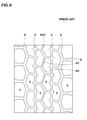
- Japanese Unexamined Patent Application Publication No. 2006-341769 discloses an improved tread pattern shown as in FIG. 9 .
- the tread pattern comprises six block rows each of which includes a plurality of tread blocks "c" defined by circumferentially extending main grooves "a” and a plurality of lateral grooves "b".
- the central main groove "a” is configures to a zigzag groove "d" in order to offer low rolling resistance while maintaining wet performance.
- the present invention has been worked out in light of the circumstances described above, and has a main object of providing a pneumatic tire that offers low rolling resistance while maintaining wet performance.
- a pneumatic tire including a tread portion provided with three to five circumferentially extending main grooves and a plurality of lateral grooves, to form a plurality of block rows each of which includes a plurality of tread blocks.
- Each tread block includes a ground contact surface having a polygonal shape that has at least five sides and each interior angle of not less than 90 degrees.
- Each ground contact surface of the tread block further includes a maximum axial width W1 positioned between its circumferentially both ends, a circumferential length L1 between its circumferentially both ends, and a ratio W1/L1 of the maximum axial width W1 to the circumferential length L1 in a range of from 0.6 to 0.9.
- the main grooves may be configured to zigzag grooves each of which includes a plurality of zigzag elements having an angle ⁇ in a range of from 10 to 30 degrees with respect to a circumferential direction of the tire.
- each both ends of the ground contact surface of the tread block may have an axial width Wa in a range of from not less than 0.3 times but less than 1.0 times in relation to the maximum axial width W1.
- each tread block may have an axially extending sipe that traverses the tread block at a circumferential center region of the tread block.
- the tread blocks may include first blocks and second blocks adjacent to the first blocks through the main groove, the first blocks and second blocks may be shifted at a certain distance in a circumferential direction of the tire, and each sipe on the first blocks and each lateral grooves between the second blocks may be communicated with the main groove at the same place in the circumferential direction of the tire.
- the tread portion has a ground contact patch under a standard loaded condition in which the tire is mounted on a standard rim with a standard pressure and is loaded with a standard tire load
- the ground contact patch includes a front edge and a rear edge.
- the front edge and rear edge of the ground contact patch may have angles ⁇ of within 10 degrees with respect to the both ends of the tread block.
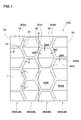
- a pneumatic tire 1 in accordance with the present invention comprises a tread portion 2 provided with three to five circumferentially extending main grooves 3 and a plurality of lateral grooves 4, to form a plurality of block rows 5R each of which includes a plurality of circumferentially arranged tread blocks 5.
- the number of main grooves 3 is three to four, and three main grooves 3 are provided on the tread portion 2, in this present embodiment.
- the tire 1 is illustrated as a heavy duty tire for trucks or busses, in this present embodiment.
- the main grooves 3 include a central main groove 3i extending on a tire equator C, and a pair of shoulder main grooves 3o disposed axially both sides the central main groove 3i.
- the block rows 5R include a pair of inner block rows 5iR each of which is defined between the adjacent central main groove 3i and shoulder main grooves 3o, and a pair of outer block rows 5oR each of which is defined between the adjacent shoulder main grooves 3o and tread edge Te.
- the inner block row 5iR includes a plurality of circumferentially arranged inner tread blocks 5i separated by inner lateral grooves 4i.
- the outer block row 5oR includes a plurality of circumferentially arranged outer tread blocks 5o separated by outer lateral grooves 4o.
- the main grooves 3 and lateral grooves 4 have groove widths W3 and W4 in a range of not less than 3mm, more preferably not less than 4mm, respectively.
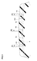
- the groove depth H3 of the main grooves 3 and the groove depth H4 of the lateral grooves 4 are the same, as shown in FIG. 3 .
- the upper limit of groove widths W3 and W4 may be determined according to a preferable land ratio of the tread pattern.
- the land ratio is a ratio of a net ground contact area to a gross total ground contact area on the tread portion.
- the land ratio of the tread portion 2 is preferably in a range of from 75% to 85%, and more preferably in a range of from 78 % to 82%.
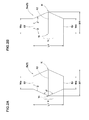
- Each tread block 5 includes a ground contact surface having a polygonal shape that has at least five sides and each interior angle ⁇ of not less than 90 degrees. As shown in FIG. 2A , the ground contact surface of inner block 5i is formed into an approximately hexagonal shape with six sides. As shown in FIG. 2A , the ground contact surface of outer block 5o is formed into an approximately pentagonal shape with five sides.
- Each ground contact surface of the tread block 5 includes circumferentially both ends Ef and Er that form lateral groove edges, respectively.
- the tread block 5 has a maximum axial width W1 positioned between its circumferentially both ends Ef and Er, and a circumferential length L1 between circumferentially both ends Ef and Er, and a ratio W1/L1 of the maximum axial width W1 to the circumferential length L1 being in a range of from 0.6 to 0.9.
- FIG. 4A shows a cross sectional view of the tread block under compressive deformation state
- FIG 4B shows a cross sectional view of the tread block under shearing deformation state along a tire rotational direction.
- FIG. 5 shows a plan view of two types of tread blocks B1 and B2.
- the tread blocks B1 and B2 have the respective same ground contact area, but the tread block B1 has less area S of its side surface Bw than that of the tread block B2.
- the amount of compressive deformation of the tread block B1 is less than that of the tread block B2.
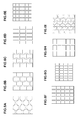
- the present inventor experimented to study the relation between total area ⁇ S of side surface of whole tread blocks on a tread portion of a tire and its rolling resistance, using various kinds of test tires of 11R22.5 14PR having different tread patterns shown in FIG. 6 and Table 1.
- FIG. 7 shows a graph showing the relation between rolling resistance of test tires and the total area ⁇ S of side surfaces of tread blocks. As shown in FIG. 7 , it was confirmed that rolling resistance of a tire is reduced by lowering its total area ⁇ S of side surface of tread blocks.
- a tread block having a ground contact surface with a polygonal shape that has at least five sides and each interior angle of not less than 90 degrees is preferable, wherein the ground contact surface of the tread block includes the maximum axial width W1 positioned between its circumferentially both ends Ef and Er.
- the ground contact surfaces of tread blocks are preferably formed into a circumferentially long shape with large cross-sectional secondary moment along the circumferential direction of the tire having a ratio W1/L1 of the maximum axial width W1 to the circumferential length L1 in a range of from 0.6 to 0.9.
- circumferentially both ends Ef and Er of the tread block are preferably extend in straight manner to reduce shearing deformation of the tread block.
- the ground contact surfaces of tread blocks are preferably formed into a pentagonal or hexagonal shape.
- the ratio W1/L1 of the tread block is more than 0.9, large shearing deformation tends to occur on the tread block.
- the ratio W1/L1 of the tread block is less than 0.6, since the tread block tends to be a circumferentially longer shape having large total area of side surfaces of the block, large compressive deformation tends to occur on the tread block.
- each both ends Ef and Er of the ground contact surface of the tread block has an axial width Wa in a range of from not less than 0.3 times but less than 1.0 times in relation to the maximum axial width W1 of the ground contact surface, in order to reduce shearing and compressive deformation on the tread block.
- the central main groove 3i and shoulder main grooves 3o are configured to zigzag grooves 10 each of which includes a plurality of zigzag elements having an angle ⁇ in a range of from 10 to 30 degrees with respect to a circumferential direction of the tire.
- the angle ⁇ is measured using the groove centerline "j" of each main groove.
- These zigzag main grooves may provide tread blocks 5 with a ground contact surface having a pentagonal or hexagonal shape with ease.
- the angle ⁇ is more than 30 degrees
- the tread block tends to undergo large shearing deformation during traveling due to small width Wa of its circumferentially both ends Ef and Er.
- the angle ⁇ is less than 10 degrees, the tread block tends to undergo large compressive deformation during traveling since total area ⁇ S of its side surface of tread blocks tends to be large.
- Each tread block 5i and 5o has an axially extending sipe 12 that traverses the tread block at its circumferential center region Y.
- the circumferential center region Y of the tread block 5 is a center part of three equal parts of its circumferential length L1 of the tread block 5.
- each sipe 12 may improve traction on wet roads. Furthermore, since each sipe 12 has a small width, the tread blocks may maintain its high circumferential rigidity that prevents from large shearing and compressive deformation thereon. Therefore, the tire having sipes 12 may offer low rolling resistance. In order to improve traction performance on wet roads while maintaining low rolling resistance of the tire, each sipe 12 preferably has a width in a range of from 0.5 to 3.0 mm, and a depth H12 in a range of from 0.75 to 1.0 times in relation to the groove depth H3 of the main grooves 3.
- Each tread block 5i and 5o has the maximum width Wa at its center region Y.
- the sipe 12 is disposed on the place of the maximum width Wa.
- the tread blocks 5 include a first block and a second block adjacent to the first block through the main groove 3.
- the first and second blocks correspond to the axially adjacent inner tread blocks 5i and 5i in a sense, respectively.
- the first and second blocks correspond to the inner and outer tread blocks 5i and 5o, respectively.
- These first block and second block are preferably shifted at a certain distance in the circumferential direction of the tire.
- the sipe 12 on the first block and the lateral groove 4 between to the second blocks are communicated with the main groove 3 at the same place in the circumferential direction of the tire.
- the sipe 12 on the first block is communicated with the main groove 3 at the place J1
- the lateral groove 4 adjacent to the second blocks is communicated with the main groove 3 at the place J2.
- the places J1 and J2 are substantially facing each other through the main groove 3 so that an extension of the sipe 12 crosses the place J1, or an extension of the lateral groove 4 crosses the place J2.
- each lateral groove 4 is communicated with a zigzag corner portion of the main groove 3. Accordingly, each place J1 where the lateral groove 4 is communicated with the main groove 3 is located at the zigzag corner portion of the main groove 3. Furthermore, each sipe 12 is communicated with the zigzag corner portion of the main groove 3. Accordingly, each place J2 where the sipe 12 is communicated with the main groove 3 is located at the zigzag corner portion of the main groove 3.
- FIG. 8 shows a ground contact patch F of the tread portion 2 of the tire 1 in accordance with the present embodiment.
- the ground contact patch F is obtained under a standard loaded condition in which the tire 1 is mounted on a standard rim with a standard pressure and is loaded with a standard tire load at a camber angle of set to zero.
- the standard wheel rim is a wheel rim officially approved or recommended for the tire by standards organizations, i.e. JATMA, TRA, ETRTO, and the like which are effective in the area where the tire is manufactured, sold or used.
- the standard wheel rim is the "standard rim” specified in JATMA, the "Measuring Rim” in ETRTO, and the "Design Rim” in TRA or the like.
- the standard pressure and the standard tire load are the maximum air pressure and the maximum tire load for the tire specified by the same organization in the Air-pressure/Maximum-load Table or similar list.
- the standard pressure is the "maximum air pressure” in JATMA, the “Inflation Pressure” in ETRTO, and the maximum pressure given in the "Tire Load Limits at Various Cold Inflation Pressures” table in TRA or the like. In case of passenger car tires, however, the standard pressure is uniformly defined by 180 kPa.
- the standard tire load is the "maximum load capacity" in JATMA, the “Load Capacity” in ETRTO, and the maximum value given in the above-mentioned table in TRA or the like.
- the ground contact patch F includes a front edge Ff and a rear edge Fr, and the front edge Ff and rear edge Fr of the ground contact patch F preferably have angles ⁇ of within 10 degrees with respect to the both ends Ef and Er of the tread block 5, respectively.
- the angle ⁇ is measured at the axially center point of the lateral groove 12.
- each block row preferably includes 35 to 45 tread blocks, more preferably 38 to 42 tread blocks.
- Pneumatic tires having a tire size of 11R22.5 14PR shown in Table 2 were made and tested with respect to rolling resistance and wet performance.
- Major common specifics of tires and test method are as follows.
- Rolling resistance of each test tire was measured under the following condition, using a tester.
- the test results are indicated by an index based on Ex.1 being 100 in Table 2. The smaller the index, the better the rolling resistance is.
- test tires were mounted on wheel rims of 7.50x22.5 with an inner pressure of 750kPa, and installed in a 2-D truck with a half load to its carrying capacity 10 tons, as its whole wheels. Then, a test driver suddenly started the truck on a wet asphalt road with a puddle 5mm deep, and measured the time for traveling to 20m distance. The test results are indicated by an index based on Ex.1 being 100 in Table 2. The smaller the index, the better the wet road performance is.
Landscapes
- Engineering & Computer Science (AREA)
- Mechanical Engineering (AREA)
- Tires In General (AREA)
Applications Claiming Priority (1)
| Application Number | Priority Date | Filing Date | Title |
|---|---|---|---|
| JP2012271624 | 2012-12-12 |
Publications (2)
| Publication Number | Publication Date |
|---|---|
| EP2743100A1 true EP2743100A1 (de) | 2014-06-18 |
| EP2743100B1 EP2743100B1 (de) | 2016-09-14 |
Family
ID=49726574
Family Applications (1)
| Application Number | Title | Priority Date | Filing Date |
|---|---|---|---|
| EP13195879.5A Not-in-force EP2743100B1 (de) | 2012-12-12 | 2013-12-05 | Luftreifen |
Country Status (4)
| Country | Link |
|---|---|
| US (1) | US9688104B2 (de) |
| EP (1) | EP2743100B1 (de) |
| JP (1) | JP6043270B2 (de) |
| CN (1) | CN103863016B (de) |
Families Citing this family (31)
| Publication number | Priority date | Publication date | Assignee | Title |
|---|---|---|---|---|
| USD733638S1 (en) * | 2014-02-19 | 2015-07-07 | Bridgestone Corporation | Tread portion of an automobile tire |
| JP6050802B2 (ja) * | 2014-11-18 | 2016-12-21 | 住友ゴム工業株式会社 | 重荷重用空気入りタイヤ |
| US10124628B2 (en) * | 2015-01-06 | 2018-11-13 | Sumitomo Rubber Industries, Ltd. | Heavy duty pneumatic tire |
| JP6514591B2 (ja) * | 2015-07-09 | 2019-05-15 | 住友ゴム工業株式会社 | 重荷重用空気入りタイヤ |
| JP6724379B2 (ja) * | 2016-01-20 | 2020-07-15 | 住友ゴム工業株式会社 | 空気入りタイヤ |
| USD781220S1 (en) | 2016-03-22 | 2017-03-14 | Bridgestone Americas Tire Operations, Llc | Tire tread |
| JP6676485B2 (ja) | 2016-06-30 | 2020-04-08 | Toyo Tire株式会社 | 空気入りタイヤ |
| JP6682386B2 (ja) * | 2016-06-30 | 2020-04-15 | Toyo Tire株式会社 | 空気入りタイヤ |
| JP6781578B2 (ja) * | 2016-06-30 | 2020-11-04 | Toyo Tire株式会社 | 空気入りタイヤ |
| JP6388013B2 (ja) * | 2016-10-26 | 2018-09-12 | 横浜ゴム株式会社 | 空気入りタイヤ |
| USD822589S1 (en) * | 2017-02-27 | 2018-07-10 | Compagnie Generale Des Etablissement Michelin | Retread band |
| US10682889B2 (en) | 2017-03-06 | 2020-06-16 | The Goodyear Tire & Rubber Company | Tire for autonomous vehicle |
| CN107031304A (zh) * | 2017-04-27 | 2017-08-11 | 杭州朝阳橡胶有限公司 | 一种适用于宽基载重汽车的雪地拖轮轮胎 |
| JP7066517B2 (ja) * | 2018-05-17 | 2022-05-13 | Toyo Tire株式会社 | 空気入りタイヤ |
| US11541693B2 (en) * | 2018-11-20 | 2023-01-03 | Sumitomo Rubber Industries, Ltd. | Tire |
| US20200290299A1 (en) * | 2019-03-15 | 2020-09-17 | Mark H. Mineur | Tire with Tread Pattern and Casing Cooperation |
| US11472232B2 (en) * | 2019-12-18 | 2022-10-18 | The Goodyear Tire & Rubber Company | Tire with tread elements including dual angled chamfer |
| CN111137073B (zh) * | 2020-01-17 | 2024-09-06 | 正新橡胶(中国)有限公司 | 一种重载荷轮胎 |
| JP7393639B2 (ja) * | 2020-01-17 | 2023-12-07 | 横浜ゴム株式会社 | タイヤ |
| FR3111292B1 (fr) * | 2020-06-10 | 2022-08-26 | Michelin & Cie | Bande de roulement de pneumatique pour un véhicule poids lourd avec une résistance aux agressions améliorée |
| WO2022098732A1 (en) | 2020-11-04 | 2022-05-12 | American Tire Engineering, Inc. | Tire tread with multiple circumferential asymmetries |
| JP7725819B2 (ja) * | 2020-12-17 | 2025-08-20 | 住友ゴム工業株式会社 | タイヤ |
| JP7815685B2 (ja) * | 2021-10-28 | 2026-02-18 | 住友ゴム工業株式会社 | 重荷重用タイヤ |
| JP7815690B2 (ja) * | 2021-11-02 | 2026-02-18 | 住友ゴム工業株式会社 | 重荷重用タイヤ |
| JP7746821B2 (ja) * | 2021-11-18 | 2025-10-01 | 住友ゴム工業株式会社 | 重荷重用タイヤ |
| USD1003229S1 (en) * | 2021-11-25 | 2023-10-31 | Compagnie Generale Des Etablissements Michelin | Tire |
| CN114329954B (zh) * | 2021-12-27 | 2025-04-15 | 中策橡胶集团股份有限公司 | 一种轮胎滚动阻力云图的绘制方法、设备和计算机程序产品 |
| CN117261497A (zh) * | 2022-06-13 | 2023-12-22 | 坦途创新智能科技(苏州)有限公司 | 轮胎及电动滑板车 |
| JP2024049099A (ja) * | 2022-09-28 | 2024-04-09 | 住友ゴム工業株式会社 | 重荷重用タイヤ |
| JP2025163608A (ja) * | 2024-04-17 | 2025-10-29 | 横浜ゴム株式会社 | タイヤ |
| JP2025163610A (ja) * | 2024-04-17 | 2025-10-29 | 横浜ゴム株式会社 | タイヤ |
Citations (3)
| Publication number | Priority date | Publication date | Assignee | Title |
|---|---|---|---|---|
| JP2006341769A (ja) | 2005-06-09 | 2006-12-21 | Sumitomo Rubber Ind Ltd | 空気入りタイヤ |
| EP2301768A1 (de) * | 2008-06-25 | 2011-03-30 | Bridgestone Corporation | Reifen |
| EP2371582A1 (de) * | 2008-11-14 | 2011-10-05 | Bridgestone Corporation | Luftreifen |
Family Cites Families (4)
| Publication number | Priority date | Publication date | Assignee | Title |
|---|---|---|---|---|
| JP4770797B2 (ja) * | 2007-06-12 | 2011-09-14 | 横浜ゴム株式会社 | 空気入りタイヤ |
| JP5364317B2 (ja) * | 2008-09-04 | 2013-12-11 | 株式会社ブリヂストン | タイヤ |
| JP5331462B2 (ja) * | 2008-11-27 | 2013-10-30 | 株式会社ブリヂストン | タイヤ |
| AU2010207199B2 (en) * | 2009-01-26 | 2012-12-13 | Bridgestone Corporation | Tire |
-
2013
- 2013-11-27 CN CN201310615945.XA patent/CN103863016B/zh not_active Expired - Fee Related
- 2013-11-29 JP JP2013248141A patent/JP6043270B2/ja not_active Expired - Fee Related
- 2013-12-05 EP EP13195879.5A patent/EP2743100B1/de not_active Not-in-force
- 2013-12-11 US US14/102,803 patent/US9688104B2/en not_active Expired - Fee Related
Patent Citations (3)
| Publication number | Priority date | Publication date | Assignee | Title |
|---|---|---|---|---|
| JP2006341769A (ja) | 2005-06-09 | 2006-12-21 | Sumitomo Rubber Ind Ltd | 空気入りタイヤ |
| EP2301768A1 (de) * | 2008-06-25 | 2011-03-30 | Bridgestone Corporation | Reifen |
| EP2371582A1 (de) * | 2008-11-14 | 2011-10-05 | Bridgestone Corporation | Luftreifen |
Also Published As
| Publication number | Publication date |
|---|---|
| EP2743100B1 (de) | 2016-09-14 |
| CN103863016A (zh) | 2014-06-18 |
| US20140158261A1 (en) | 2014-06-12 |
| US9688104B2 (en) | 2017-06-27 |
| JP6043270B2 (ja) | 2016-12-14 |
| JP2014133549A (ja) | 2014-07-24 |
| CN103863016B (zh) | 2017-09-08 |
Similar Documents
| Publication | Publication Date | Title |
|---|---|---|
| EP2743100B1 (de) | Luftreifen | |
| US10710415B2 (en) | Tire | |
| EP3153334B1 (de) | Reifen | |
| EP2614966B1 (de) | LKW-Luftreifen | |
| EP3205516B1 (de) | Luftreifen | |
| EP3153333B1 (de) | Luftreifen | |
| EP2777950B1 (de) | Luftreifen | |
| EP2767413B1 (de) | LKW-Luftreifen | |
| EP2639084A1 (de) | Luftreifen | |
| EP2907674A1 (de) | Luftreifen | |
| EP3042792B1 (de) | Luftreifen | |
| EP3263365B1 (de) | Reifen | |
| EP2765010B1 (de) | LKW-Luftreifen | |
| EP2650145B1 (de) | Luftreifen zum Fahren auf unebenem Gelände | |
| EP3552844B1 (de) | Reifen | |
| EP3332991B1 (de) | Luftreifen | |
| US10953701B2 (en) | Tire | |
| EP3549794B1 (de) | Reifen | |
| EP1712377A1 (de) | Luftreifen | |
| EP3031624B1 (de) | Luftreifen | |
| EP3967520B1 (de) | Reifen mit laufflächenrillen | |
| EP4201709B1 (de) | Reifen | |
| EP4015244B1 (de) | Reifen | |
| EP3705315B1 (de) | Reifen | |
| EP4122719A1 (de) | Reifen |
Legal Events
| Date | Code | Title | Description |
|---|---|---|---|
| PUAI | Public reference made under article 153(3) epc to a published international application that has entered the european phase |
Free format text: ORIGINAL CODE: 0009012 |
|
| 17P | Request for examination filed |
Effective date: 20131205 |
|
| AK | Designated contracting states |
Kind code of ref document: A1 Designated state(s): AL AT BE BG CH CY CZ DE DK EE ES FI FR GB GR HR HU IE IS IT LI LT LU LV MC MK MT NL NO PL PT RO RS SE SI SK SM TR |
|
| AX | Request for extension of the european patent |
Extension state: BA ME |
|
| R17P | Request for examination filed (corrected) |
Effective date: 20141211 |
|
| RBV | Designated contracting states (corrected) |
Designated state(s): AL AT BE BG CH CY CZ DE DK EE ES FI FR GB GR HR HU IE IS IT LI LT LU LV MC MK MT NL NO PL PT RO RS SE SI SK SM TR |
|
| RIC1 | Information provided on ipc code assigned before grant |
Ipc: B60C 11/11 20060101ALI20160217BHEP Ipc: B60C 11/03 20060101AFI20160217BHEP Ipc: B60C 11/12 20060101ALI20160217BHEP |
|
| GRAP | Despatch of communication of intention to grant a patent |
Free format text: ORIGINAL CODE: EPIDOSNIGR1 |
|
| INTG | Intention to grant announced |
Effective date: 20160419 |
|
| GRAS | Grant fee paid |
Free format text: ORIGINAL CODE: EPIDOSNIGR3 |
|
| GRAA | (expected) grant |
Free format text: ORIGINAL CODE: 0009210 |
|
| AK | Designated contracting states |
Kind code of ref document: B1 Designated state(s): AL AT BE BG CH CY CZ DE DK EE ES FI FR GB GR HR HU IE IS IT LI LT LU LV MC MK MT NL NO PL PT RO RS SE SI SK SM TR |
|
| REG | Reference to a national code |
Ref country code: GB Ref legal event code: FG4D |
|
| REG | Reference to a national code |
Ref country code: CH Ref legal event code: EP |
|
| REG | Reference to a national code |
Ref country code: IE Ref legal event code: FG4D |
|
| REG | Reference to a national code |
Ref country code: AT Ref legal event code: REF Ref document number: 828525 Country of ref document: AT Kind code of ref document: T Effective date: 20161015 |
|
| REG | Reference to a national code |
Ref country code: DE Ref legal event code: R096 Ref document number: 602013011429 Country of ref document: DE |
|
| REG | Reference to a national code |
Ref country code: FR Ref legal event code: PLFP Year of fee payment: 4 |
|
| REG | Reference to a national code |
Ref country code: LT Ref legal event code: MG4D |
|
| REG | Reference to a national code |
Ref country code: NL Ref legal event code: MP Effective date: 20160914 |
|
| PG25 | Lapsed in a contracting state [announced via postgrant information from national office to epo] |
Ref country code: RS Free format text: LAPSE BECAUSE OF FAILURE TO SUBMIT A TRANSLATION OF THE DESCRIPTION OR TO PAY THE FEE WITHIN THE PRESCRIBED TIME-LIMIT Effective date: 20160914 Ref country code: LT Free format text: LAPSE BECAUSE OF FAILURE TO SUBMIT A TRANSLATION OF THE DESCRIPTION OR TO PAY THE FEE WITHIN THE PRESCRIBED TIME-LIMIT Effective date: 20160914 Ref country code: NO Free format text: LAPSE BECAUSE OF FAILURE TO SUBMIT A TRANSLATION OF THE DESCRIPTION OR TO PAY THE FEE WITHIN THE PRESCRIBED TIME-LIMIT Effective date: 20161214 Ref country code: FI Free format text: LAPSE BECAUSE OF FAILURE TO SUBMIT A TRANSLATION OF THE DESCRIPTION OR TO PAY THE FEE WITHIN THE PRESCRIBED TIME-LIMIT Effective date: 20160914 Ref country code: HR Free format text: LAPSE BECAUSE OF FAILURE TO SUBMIT A TRANSLATION OF THE DESCRIPTION OR TO PAY THE FEE WITHIN THE PRESCRIBED TIME-LIMIT Effective date: 20160914 |
|
| REG | Reference to a national code |
Ref country code: AT Ref legal event code: MK05 Ref document number: 828525 Country of ref document: AT Kind code of ref document: T Effective date: 20160914 |
|
| PG25 | Lapsed in a contracting state [announced via postgrant information from national office to epo] |
Ref country code: GR Free format text: LAPSE BECAUSE OF FAILURE TO SUBMIT A TRANSLATION OF THE DESCRIPTION OR TO PAY THE FEE WITHIN THE PRESCRIBED TIME-LIMIT Effective date: 20161215 Ref country code: SE Free format text: LAPSE BECAUSE OF FAILURE TO SUBMIT A TRANSLATION OF THE DESCRIPTION OR TO PAY THE FEE WITHIN THE PRESCRIBED TIME-LIMIT Effective date: 20160914 Ref country code: NL Free format text: LAPSE BECAUSE OF FAILURE TO SUBMIT A TRANSLATION OF THE DESCRIPTION OR TO PAY THE FEE WITHIN THE PRESCRIBED TIME-LIMIT Effective date: 20160914 Ref country code: LV Free format text: LAPSE BECAUSE OF FAILURE TO SUBMIT A TRANSLATION OF THE DESCRIPTION OR TO PAY THE FEE WITHIN THE PRESCRIBED TIME-LIMIT Effective date: 20160914 |
|
| PG25 | Lapsed in a contracting state [announced via postgrant information from national office to epo] |
Ref country code: EE Free format text: LAPSE BECAUSE OF FAILURE TO SUBMIT A TRANSLATION OF THE DESCRIPTION OR TO PAY THE FEE WITHIN THE PRESCRIBED TIME-LIMIT Effective date: 20160914 Ref country code: RO Free format text: LAPSE BECAUSE OF FAILURE TO SUBMIT A TRANSLATION OF THE DESCRIPTION OR TO PAY THE FEE WITHIN THE PRESCRIBED TIME-LIMIT Effective date: 20160914 |
|
| PG25 | Lapsed in a contracting state [announced via postgrant information from national office to epo] |
Ref country code: AT Free format text: LAPSE BECAUSE OF FAILURE TO SUBMIT A TRANSLATION OF THE DESCRIPTION OR TO PAY THE FEE WITHIN THE PRESCRIBED TIME-LIMIT Effective date: 20160914 Ref country code: BE Free format text: LAPSE BECAUSE OF FAILURE TO SUBMIT A TRANSLATION OF THE DESCRIPTION OR TO PAY THE FEE WITHIN THE PRESCRIBED TIME-LIMIT Effective date: 20160914 Ref country code: SM Free format text: LAPSE BECAUSE OF FAILURE TO SUBMIT A TRANSLATION OF THE DESCRIPTION OR TO PAY THE FEE WITHIN THE PRESCRIBED TIME-LIMIT Effective date: 20160914 Ref country code: CZ Free format text: LAPSE BECAUSE OF FAILURE TO SUBMIT A TRANSLATION OF THE DESCRIPTION OR TO PAY THE FEE WITHIN THE PRESCRIBED TIME-LIMIT Effective date: 20160914 Ref country code: PL Free format text: LAPSE BECAUSE OF FAILURE TO SUBMIT A TRANSLATION OF THE DESCRIPTION OR TO PAY THE FEE WITHIN THE PRESCRIBED TIME-LIMIT Effective date: 20160914 Ref country code: IS Free format text: LAPSE BECAUSE OF FAILURE TO SUBMIT A TRANSLATION OF THE DESCRIPTION OR TO PAY THE FEE WITHIN THE PRESCRIBED TIME-LIMIT Effective date: 20170114 Ref country code: BG Free format text: LAPSE BECAUSE OF FAILURE TO SUBMIT A TRANSLATION OF THE DESCRIPTION OR TO PAY THE FEE WITHIN THE PRESCRIBED TIME-LIMIT Effective date: 20161214 Ref country code: SK Free format text: LAPSE BECAUSE OF FAILURE TO SUBMIT A TRANSLATION OF THE DESCRIPTION OR TO PAY THE FEE WITHIN THE PRESCRIBED TIME-LIMIT Effective date: 20160914 Ref country code: PT Free format text: LAPSE BECAUSE OF FAILURE TO SUBMIT A TRANSLATION OF THE DESCRIPTION OR TO PAY THE FEE WITHIN THE PRESCRIBED TIME-LIMIT Effective date: 20170116 Ref country code: ES Free format text: LAPSE BECAUSE OF FAILURE TO SUBMIT A TRANSLATION OF THE DESCRIPTION OR TO PAY THE FEE WITHIN THE PRESCRIBED TIME-LIMIT Effective date: 20160914 |
|
| REG | Reference to a national code |
Ref country code: DE Ref legal event code: R097 Ref document number: 602013011429 Country of ref document: DE |
|
| PLBE | No opposition filed within time limit |
Free format text: ORIGINAL CODE: 0009261 |
|
| STAA | Information on the status of an ep patent application or granted ep patent |
Free format text: STATUS: NO OPPOSITION FILED WITHIN TIME LIMIT |
|
| PG25 | Lapsed in a contracting state [announced via postgrant information from national office to epo] |
Ref country code: DK Free format text: LAPSE BECAUSE OF FAILURE TO SUBMIT A TRANSLATION OF THE DESCRIPTION OR TO PAY THE FEE WITHIN THE PRESCRIBED TIME-LIMIT Effective date: 20160914 |
|
| REG | Reference to a national code |
Ref country code: CH Ref legal event code: PL |
|
| 26N | No opposition filed |
Effective date: 20170615 |
|
| PG25 | Lapsed in a contracting state [announced via postgrant information from national office to epo] |
Ref country code: MC Free format text: LAPSE BECAUSE OF FAILURE TO SUBMIT A TRANSLATION OF THE DESCRIPTION OR TO PAY THE FEE WITHIN THE PRESCRIBED TIME-LIMIT Effective date: 20160914 |
|
| REG | Reference to a national code |
Ref country code: IE Ref legal event code: MM4A |
|
| PG25 | Lapsed in a contracting state [announced via postgrant information from national office to epo] |
Ref country code: LI Free format text: LAPSE BECAUSE OF NON-PAYMENT OF DUE FEES Effective date: 20161231 Ref country code: CH Free format text: LAPSE BECAUSE OF NON-PAYMENT OF DUE FEES Effective date: 20161231 Ref country code: LU Free format text: LAPSE BECAUSE OF NON-PAYMENT OF DUE FEES Effective date: 20161205 |
|
| REG | Reference to a national code |
Ref country code: FR Ref legal event code: PLFP Year of fee payment: 5 |
|
| PG25 | Lapsed in a contracting state [announced via postgrant information from national office to epo] |
Ref country code: IE Free format text: LAPSE BECAUSE OF NON-PAYMENT OF DUE FEES Effective date: 20161205 Ref country code: SI Free format text: LAPSE BECAUSE OF FAILURE TO SUBMIT A TRANSLATION OF THE DESCRIPTION OR TO PAY THE FEE WITHIN THE PRESCRIBED TIME-LIMIT Effective date: 20160914 |
|
| PG25 | Lapsed in a contracting state [announced via postgrant information from national office to epo] |
Ref country code: HU Free format text: LAPSE BECAUSE OF FAILURE TO SUBMIT A TRANSLATION OF THE DESCRIPTION OR TO PAY THE FEE WITHIN THE PRESCRIBED TIME-LIMIT; INVALID AB INITIO Effective date: 20131205 |
|
| PG25 | Lapsed in a contracting state [announced via postgrant information from national office to epo] |
Ref country code: MK Free format text: LAPSE BECAUSE OF FAILURE TO SUBMIT A TRANSLATION OF THE DESCRIPTION OR TO PAY THE FEE WITHIN THE PRESCRIBED TIME-LIMIT Effective date: 20160914 Ref country code: CY Free format text: LAPSE BECAUSE OF FAILURE TO SUBMIT A TRANSLATION OF THE DESCRIPTION OR TO PAY THE FEE WITHIN THE PRESCRIBED TIME-LIMIT Effective date: 20160914 |
|
| GBPC | Gb: european patent ceased through non-payment of renewal fee |
Effective date: 20171205 |
|
| PG25 | Lapsed in a contracting state [announced via postgrant information from national office to epo] |
Ref country code: MT Free format text: LAPSE BECAUSE OF NON-PAYMENT OF DUE FEES Effective date: 20161205 |
|
| PG25 | Lapsed in a contracting state [announced via postgrant information from national office to epo] |
Ref country code: AL Free format text: LAPSE BECAUSE OF FAILURE TO SUBMIT A TRANSLATION OF THE DESCRIPTION OR TO PAY THE FEE WITHIN THE PRESCRIBED TIME-LIMIT Effective date: 20160914 Ref country code: TR Free format text: LAPSE BECAUSE OF FAILURE TO SUBMIT A TRANSLATION OF THE DESCRIPTION OR TO PAY THE FEE WITHIN THE PRESCRIBED TIME-LIMIT Effective date: 20160914 |
|
| PG25 | Lapsed in a contracting state [announced via postgrant information from national office to epo] |
Ref country code: GB Free format text: LAPSE BECAUSE OF NON-PAYMENT OF DUE FEES Effective date: 20171205 |
|
| PGFP | Annual fee paid to national office [announced via postgrant information from national office to epo] |
Ref country code: IT Payment date: 20221111 Year of fee payment: 10 Ref country code: FR Payment date: 20221110 Year of fee payment: 10 Ref country code: DE Payment date: 20221102 Year of fee payment: 10 |
|
| REG | Reference to a national code |
Ref country code: DE Ref legal event code: R119 Ref document number: 602013011429 Country of ref document: DE |
|
| PG25 | Lapsed in a contracting state [announced via postgrant information from national office to epo] |
Ref country code: DE Free format text: LAPSE BECAUSE OF NON-PAYMENT OF DUE FEES Effective date: 20240702 |
|
| PG25 | Lapsed in a contracting state [announced via postgrant information from national office to epo] |
Ref country code: FR Free format text: LAPSE BECAUSE OF NON-PAYMENT OF DUE FEES Effective date: 20231231 |
|
| PG25 | Lapsed in a contracting state [announced via postgrant information from national office to epo] |
Ref country code: FR Free format text: LAPSE BECAUSE OF NON-PAYMENT OF DUE FEES Effective date: 20231231 Ref country code: DE Free format text: LAPSE BECAUSE OF NON-PAYMENT OF DUE FEES Effective date: 20240702 |
|
| PG25 | Lapsed in a contracting state [announced via postgrant information from national office to epo] |
Ref country code: IT Free format text: LAPSE BECAUSE OF NON-PAYMENT OF DUE FEES Effective date: 20231205 |