EP3205516B1 - Luftreifen - Google Patents
Luftreifen Download PDFInfo
- Publication number
- EP3205516B1 EP3205516B1 EP17153654.3A EP17153654A EP3205516B1 EP 3205516 B1 EP3205516 B1 EP 3205516B1 EP 17153654 A EP17153654 A EP 17153654A EP 3205516 B1 EP3205516 B1 EP 3205516B1
- Authority
- EP
- European Patent Office
- Prior art keywords
- sipe
- transverse
- land region
- tire
- pneumatic tire
- Prior art date
- Legal status (The legal status is an assumption and is not a legal conclusion. Google has not performed a legal analysis and makes no representation as to the accuracy of the status listed.)
- Active
Links
Images


Classifications
-
- B—PERFORMING OPERATIONS; TRANSPORTING
- B60—VEHICLES IN GENERAL
- B60C—VEHICLE TYRES; TYRE INFLATION; TYRE CHANGING; CONNECTING VALVES TO INFLATABLE ELASTIC BODIES IN GENERAL; DEVICES OR ARRANGEMENTS RELATED TO TYRES
- B60C11/00—Tyre tread bands; Tread patterns; Anti-skid inserts
- B60C11/03—Tread patterns
- B60C11/12—Tread patterns characterised by the use of narrow slits or incisions, e.g. sipes
- B60C11/1259—Depth of the sipe
- B60C11/1263—Depth of the sipe different within the same sipe
-
- B—PERFORMING OPERATIONS; TRANSPORTING
- B60—VEHICLES IN GENERAL
- B60C—VEHICLE TYRES; TYRE INFLATION; TYRE CHANGING; CONNECTING VALVES TO INFLATABLE ELASTIC BODIES IN GENERAL; DEVICES OR ARRANGEMENTS RELATED TO TYRES
- B60C11/00—Tyre tread bands; Tread patterns; Anti-skid inserts
- B60C11/03—Tread patterns
- B60C11/04—Tread patterns in which the raised area of the pattern consists only of continuous circumferential ribs, e.g. zig-zag
-
- B—PERFORMING OPERATIONS; TRANSPORTING
- B60—VEHICLES IN GENERAL
- B60C—VEHICLE TYRES; TYRE INFLATION; TYRE CHANGING; CONNECTING VALVES TO INFLATABLE ELASTIC BODIES IN GENERAL; DEVICES OR ARRANGEMENTS RELATED TO TYRES
- B60C11/00—Tyre tread bands; Tread patterns; Anti-skid inserts
- B60C11/03—Tread patterns
- B60C11/12—Tread patterns characterised by the use of narrow slits or incisions, e.g. sipes
-
- B—PERFORMING OPERATIONS; TRANSPORTING
- B60—VEHICLES IN GENERAL
- B60C—VEHICLE TYRES; TYRE INFLATION; TYRE CHANGING; CONNECTING VALVES TO INFLATABLE ELASTIC BODIES IN GENERAL; DEVICES OR ARRANGEMENTS RELATED TO TYRES
- B60C11/00—Tyre tread bands; Tread patterns; Anti-skid inserts
- B60C11/03—Tread patterns
- B60C11/12—Tread patterns characterised by the use of narrow slits or incisions, e.g. sipes
- B60C11/1204—Tread patterns characterised by the use of narrow slits or incisions, e.g. sipes with special shape of the sipe
-
- B—PERFORMING OPERATIONS; TRANSPORTING
- B60—VEHICLES IN GENERAL
- B60C—VEHICLE TYRES; TYRE INFLATION; TYRE CHANGING; CONNECTING VALVES TO INFLATABLE ELASTIC BODIES IN GENERAL; DEVICES OR ARRANGEMENTS RELATED TO TYRES
- B60C11/00—Tyre tread bands; Tread patterns; Anti-skid inserts
- B60C11/03—Tread patterns
- B60C11/12—Tread patterns characterised by the use of narrow slits or incisions, e.g. sipes
- B60C11/1236—Tread patterns characterised by the use of narrow slits or incisions, e.g. sipes with special arrangements in the tread pattern
-
- B—PERFORMING OPERATIONS; TRANSPORTING
- B60—VEHICLES IN GENERAL
- B60C—VEHICLE TYRES; TYRE INFLATION; TYRE CHANGING; CONNECTING VALVES TO INFLATABLE ELASTIC BODIES IN GENERAL; DEVICES OR ARRANGEMENTS RELATED TO TYRES
- B60C11/00—Tyre tread bands; Tread patterns; Anti-skid inserts
- B60C11/03—Tread patterns
- B60C11/13—Tread patterns characterised by the groove cross-section, e.g. for buttressing or preventing stone-trapping
-
- B—PERFORMING OPERATIONS; TRANSPORTING
- B60—VEHICLES IN GENERAL
- B60C—VEHICLE TYRES; TYRE INFLATION; TYRE CHANGING; CONNECTING VALVES TO INFLATABLE ELASTIC BODIES IN GENERAL; DEVICES OR ARRANGEMENTS RELATED TO TYRES
- B60C11/00—Tyre tread bands; Tread patterns; Anti-skid inserts
- B60C11/03—Tread patterns
- B60C11/13—Tread patterns characterised by the groove cross-section, e.g. for buttressing or preventing stone-trapping
- B60C11/1376—Three dimensional block surfaces departing from the enveloping tread contour
- B60C11/1392—Three dimensional block surfaces departing from the enveloping tread contour with chamfered block edges
-
- B—PERFORMING OPERATIONS; TRANSPORTING
- B60—VEHICLES IN GENERAL
- B60C—VEHICLE TYRES; TYRE INFLATION; TYRE CHANGING; CONNECTING VALVES TO INFLATABLE ELASTIC BODIES IN GENERAL; DEVICES OR ARRANGEMENTS RELATED TO TYRES
- B60C11/00—Tyre tread bands; Tread patterns; Anti-skid inserts
- B60C11/03—Tread patterns
- B60C2011/0337—Tread patterns characterised by particular design features of the pattern
- B60C2011/0339—Grooves
- B60C2011/0341—Circumferential grooves
-
- B—PERFORMING OPERATIONS; TRANSPORTING
- B60—VEHICLES IN GENERAL
- B60C—VEHICLE TYRES; TYRE INFLATION; TYRE CHANGING; CONNECTING VALVES TO INFLATABLE ELASTIC BODIES IN GENERAL; DEVICES OR ARRANGEMENTS RELATED TO TYRES
- B60C11/00—Tyre tread bands; Tread patterns; Anti-skid inserts
- B60C11/03—Tread patterns
- B60C2011/0337—Tread patterns characterised by particular design features of the pattern
- B60C2011/0339—Grooves
- B60C2011/0341—Circumferential grooves
- B60C2011/0348—Narrow grooves, i.e. having a width of less than 4 mm
-
- B—PERFORMING OPERATIONS; TRANSPORTING
- B60—VEHICLES IN GENERAL
- B60C—VEHICLE TYRES; TYRE INFLATION; TYRE CHANGING; CONNECTING VALVES TO INFLATABLE ELASTIC BODIES IN GENERAL; DEVICES OR ARRANGEMENTS RELATED TO TYRES
- B60C11/00—Tyre tread bands; Tread patterns; Anti-skid inserts
- B60C11/03—Tread patterns
- B60C2011/0337—Tread patterns characterised by particular design features of the pattern
- B60C2011/0386—Continuous ribs
- B60C2011/0388—Continuous ribs provided at the equatorial plane
-
- B—PERFORMING OPERATIONS; TRANSPORTING
- B60—VEHICLES IN GENERAL
- B60C—VEHICLE TYRES; TYRE INFLATION; TYRE CHANGING; CONNECTING VALVES TO INFLATABLE ELASTIC BODIES IN GENERAL; DEVICES OR ARRANGEMENTS RELATED TO TYRES
- B60C11/00—Tyre tread bands; Tread patterns; Anti-skid inserts
- B60C11/03—Tread patterns
- B60C11/12—Tread patterns characterised by the use of narrow slits or incisions, e.g. sipes
- B60C11/1204—Tread patterns characterised by the use of narrow slits or incisions, e.g. sipes with special shape of the sipe
- B60C2011/1213—Tread patterns characterised by the use of narrow slits or incisions, e.g. sipes with special shape of the sipe sinusoidal or zigzag at the tread surface
-
- B—PERFORMING OPERATIONS; TRANSPORTING
- B60—VEHICLES IN GENERAL
- B60C—VEHICLE TYRES; TYRE INFLATION; TYRE CHANGING; CONNECTING VALVES TO INFLATABLE ELASTIC BODIES IN GENERAL; DEVICES OR ARRANGEMENTS RELATED TO TYRES
- B60C11/00—Tyre tread bands; Tread patterns; Anti-skid inserts
- B60C11/03—Tread patterns
- B60C11/12—Tread patterns characterised by the use of narrow slits or incisions, e.g. sipes
- B60C11/1259—Depth of the sipe
- B60C2011/1268—Depth of the sipe being different from sipe to sipe
Definitions
- the present invention relates to a pneumatic tire improved in both the steering stability on dry roads and the running performance on snowy/icy roads.
- Japanese Patent Application Publication No. 2006-160055 discloses a pneumatic tire having land regions provided with straight sipes and L-shaped sipes in order to improve on-the-snow performance.
- Such straight or L-shaped sipe exert its edge effect to increase a frictional force only in one specific direction or two specific directions. Further, simply providing the land region with sipes tends to reduce the rigidity of the land region, and thereby the steering stability on dry roads tends to deteriorate.
- a pneumatic tire according to the preamble of claim 1 is known from documents EP 2 050 588 A1 and JP 2012 020620 A . Further, document DE 10 2010 060933 A1 discloses a pneumatic tire with a tread portion provided with straight sipes of varying depth across their length.
- the present invention was therefore made in view of the above, and a primary object of the present invention is to provide a pneumatic tire which is improved in the steering stability on dry roads and running performance on snowy/icy roads by improving the configurations of transverse sipes.
- a pneumatic tire comprises:
- At least a part of the first portion has a constant depth
- at least a part of the second portion has a constant depth
- the depth of the transverse sipe varies in a range of the transverse sipe which range includes an interconnecting portion between the first portion and the second portion.
- the transverse sipe consists of the first portion and the second portion.
- the first portion curves with a constant radius R1 of curvature from one of the edges of the circumferential land region in the tire axial direction to a central portion of the circumferential land region in the tire axial direction
- the second portion curves with a constant radius R2 of curvature from the other edge of the circumferential land region in the tire axial direction to the central portion of the circumferential land region in the tire axial direction.
- the radii R1 and R2 of curvature are preferably in a range from 15 to 25 mm.
- first transverse sipe and the second transverse sipe are arranged alternately in the tire circumferential direction.
- the circumferential land region is a crown rib disposed on the tire equator and provided only with the above-mentioned transverse sipes.
- the tread portion is provided with circumferentially continuously extending main grooves including a pair of axially outermost shoulder main grooves and a pair of crown main grooves therebetween so that the tread portion is axially divided into a shoulder land region axially outside each of the shoulder main grooves, a middle land region between each of the shoulder main grooves and the adjacent crown main groove, and a crown land region between the crown main grooves, and the crown land region is the above-mentioned circumferential land region provided with the transverse sipes.
- the above-mentioned middle land region is a row of circumferentially arranged middle blocks, and the middle blocks are each provided with a pair of a first combined sipe and a second combined sipe each composed of an axially inner arc-shaped curved portion and an axially outer straight portion, wherein the first combined sipe has a variable depth such that a maximum depth of the curved portion is greater than a maximum depth of the straight portion, whereas the second combined sipe has a variable depth such that a maximum depth of the straight portion is greater than a maximum depth of the curved portion.
- the middle blocks are each provided with a circumferential sipe connecting between the first combined sipe and the second combined sipe and positioned on the axially inside of an axial center position of the middle block.
- a subdivided part of each said middle block defined between the first and second combined sipes is provided with a chamfer in a corner between a ground contacting top surface of the subdivided part and a sidewall of the subdivided part adjacent to the above-mentioned shoulder main groove.
- the above-mentioned shoulder land region is provided with plural pairs of shoulder sipes extending axially outwardly from the above-mentioned shoulder main groove, each subdivided part of the shoulder land region defined between one of the pairs of the shoulder sipes is provided with a second chamfer in a corner between a ground contacting top surface of the subdivided part and a sidewall of the subdivided part adjacent to the above-mentioned shoulder main groove, wherein the above-mentioned second chamfer is at least partially overlapped in the tire circumferential direction with one of the chamfers of the middle blocks.
- the transverse sipes have a wavy configuration and can increase not only a frictional force in the tire circumferential direction but also a frictional force in the tire axial direction.
- the cornering performance on snowy/icy roads is improved.
- the opposite sidewalls of the transverse sipe can engage with each other during running to maintain the apparent rigidity of the circumferential land region and thereby to maintain the steering stability on dry roads.
- the rigidity of the circumferential land region can be maintained, and at the same time, a large frictional force can be obtained by the deep portions of the transverse sipes.
- the steering stability on dry roads and the running performance on snowy/icy roads are improved in a good balance.
- the rigidity distribution of the circumferential land region becomes uniform, and uneven wear of the circumferential land region can be suppressed.
- the normally inflated unloaded condition is such that the tire is mounted on a standard wheel rim and inflate to a standard pressure but loaded with no tire load.
- the undermentioned normally inflated loaded condition is such that the tire is mounted on the standard wheel rim and inflated to the standard pressure and loaded with the standard tire load.
- the standard wheel rim is a wheel rim officially approved or recommended for the tire by standards organizations, i.e. JATMA (Japan and Asia), T&RA (North America), ETRTO (Europe), TRAA (Australia), STRO (Scandinavia), ALAPA (Latin America), ITTAC (India) and the like which are effective in the area where the tire is manufactured, sold or used.
- the standard pressure and the standard tire load are the maximum air pressure and the maximum tire load for the tire specified by the same organization in the Air-pressure/Maximum-load Table or similar list.
- the standard wheel rim is the "standard rim” specified in JATMA, the "Measuring Rim” in ETRTO, the "Design Rim” in TRA or the like.
- the standard pressure is the “maximum air pressure” in JATMA, the “Inflation Pressure” in ETRTO, the maximum pressure given in the “Tire Load Limits at various Cold Inflation Pressures” table in TRA or the like.
- the standard load is the "maximum load capacity" in JATMA, the “Load Capacity” in ETRTO, the maximum value given in the above-mentioned table in TRA or the like.
- the tread edges Te are the axial outermost edges of the ground contacting patch of the tire which occurs under the normally inflated loaded condition when the camber angle of the tire is zero.
- the tread width TW is the width measured under the normally inflated unloaded condition, as the axial distance between the tread edges Te determined as above.
- peel means a very narrow groove having a width of not greater than 1.5 mm inclusive of a cut with no substantial width.
- a pneumatic tire 1 as an embodiment of the present invention is a winter tire for passenger cars, but the present invention is not limited thereto.
- a pneumatic tire comprises a tread portion whose outer surface defines the tread, a pair of axially spaced bead portions mounted on rim seats, a pair of sidewall portions extending between the tread edges and the bead portions, a carcass extending between the bead portions through the tread portion and the sidewall portions, and a tread reinforcing belt disposed radially outside the carcass in the tread portion as well known in the art.
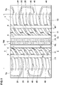
- the tread portion 2 As shown in Fig. 1 which shows the tread portion 2 of the pneumatic tire 1, the tread portion 2 is provided with main grooves 3 defined as extending continuously in the tire circumferential direction, and the tread portion 2 is axially divided into circumferential land regions 6 by the main grooves 3.
- the main grooves 3 are a pair of shoulder main grooves 4 disposed one on each side of the tire equator C as the axially outermost main grooves, and at least one crown main groove 5 disposed between the shoulder main grooves 4.
- two crown main grooves 5 are disposed one on each side of the tire equator C.
- the above-mentioned at least one crown main groove 5 may be a single groove disposed on the tire equator C.
- each of the main grooves 4 and 5 is a linear groove extending straight in the tire circumferential direction with a constant groove width.
- each of or some of the main grooves 4 and 5 may be a nonlinear groove extending zigzag or wavy in the tire circumferential direction.
- the main grooves 4 and 5 each have a groove width W1 of from 2 to 9 % of then tread width TW.
- the main grooves 4 and 5 each have a depth of from 5.0 to 15.0 mm, for example.
- the main groove 4, 5 configured as such is helpful in improving the steering stability on dry roads and the running performance on snowy/icy roads in a good balance.
- the circumferential land regions 6 in this embodiment are one crown land region 10 between the crown main grooves 5 which is disposed on the tire equator C, two middle land regions 11 between the crown main grooves 5 and the shoulder main grooves 4, and two shoulder land regions 12 between the shoulder main grooves 4 and the tread edges Te.
- the crown land region 10 is provided with a plurality of transverse sipes 15 extending across the entire width of the crown land region 10.
- the crown land region 10 in this example is a crown rib provided with only the transverse sipes 15 and no transverse grooves having a width greater than 1.5 mm.
- the crown rib configured as such has a high rigidity, therefore, it is possible to maintain the steering stability on dry roads.
- Each of the transverse sipes 15 comprises an arc-shaped first portion 18 convexed toward one side in the tire circumferential direction (upper side in Fig. 2 ) and an arc-shaped second portion 19 convexed toward the other side in the tire circumferential direction (lower side in Fig. 2 ) and connected with the first portion 18 so as to have a wavy configuration.
- the transverse sipe 15 configured as such can increase the frictional force not only in the tire circumferential direction but also in the tire axial direction.
- the transverse sipe 15 can exert a high frictional force substantially in all directions by the first portion 18 and the second portion 19. Thereby, it is possible to improve the cornering performance on snowy/icy roads.
- the opposite sidewalls of the transverse sipe 15 having the wavy configuration can engage with each other when the land region is subjected to a lateral force during running, and the parts of the land region circumferentially subdivided by the sipes can be prevented from shifting from each other in the tire axial direction. Accordingly, the apparent lateral rigidity of the land region is maintained, and it is possible to prevent the steering stability on dry roads from deteriorating.
- the transverse sipes 15 include a first transverse sipe 16 and a second transverse sipe 17.
- the first transverse sipe 16 and the second transverse sipe 17 are similarly to each other in their top views, but these two types of sipes 16 and 17 have different depth variations.
- the first transverse sipe 16 is configured such that the depth d1 of the arc-shaped first portion 18 is greater than the depth d2 of the arc-shaped second portion 19.
- the second transverse sipe 17 is configured such that the depth d4 of the arc-shaped second portion 19 is greater than the depth d3 of the arc-shaped first portion 18.
- first and second transverse sipes 16 and 17 each comprise the first and second portions 18 and 19 whose depths are different from each other, it is possible to maintain the rigidity of the circumferential land region by the shallow portions, and at the same time, a large frictional force owing to the sipe edges can be obtained by the deep portions. Thereby, the steering stability on dry roads and the running performance on snowy/icy roads can be improved in a good balance.
- the first transverse sipe 16 and the second transverse sipe 17 in this embodiment in order to further enhance the above described effects, at least a part of the arc-shaped first portion 18 has a constant depth along its longitudinal direction, and at least a part of the arc-shaped second portion 19 has a constant depth along its longitudinal direction.
- the arc-shaped first portion 18 has a constant depth over its entire length
- the arc-shaped second portion 19 has a constant depth over its entire length.
- the depth of the first/second transverse sipe 16/17 varies only in an interconnecting portion 20 of the transverse sipe which portion connects between the arc-shaped first portion 18 and the arc-shaped second portion 19.
- the crown land region 10 provided with the transverse sipes 15 configured as such has an increased rigidity in each lateral portion in the tire axial direction, therefore, it is possible to turn impact sounds into white noise during running on dry roads.
- the depth d1 of the first portion 18 of the first transverse sipe 16 and the depth d4 of the second portion 19 of the second transverse sipe 17 are preferably set in a range from 0.65 to 0.75 times the depth d5 of the crown main groove 5
- the depth d2 of the second portion 19 of the first transverse sipe 16 and the depth d3 of the first portion 18 of the second transverse sipe 17 are preferably set in a range from 0.45 to 0.55 times the depth d5 of the crown main groove 5.
- the first transverse sipe 16 and second transverse sipe 17 configured as such can maintain the rigidity of the crown land region 10 while providing a great frictional force by their edges.
- the first transverse sipe 16 and the second transverse sipe 17 in this embodiment are provided periodically in the tire circumferential direction.
- a typical example of the periodic arrangement is an alternate arrangement.
- a group of two or three of the first transverse sipe 16 and a group of two or three of the second transverse sipe 17 may be arranged alternately.
- the transverse sipes 15 (16 and 17) are arranged at a circumferential pitch P1 of from 0.20 to 0.30 times a width W2 of the crown land region 10.
- the transverse sipes 16 and 17 arranged as such can exert the sufficient edge effect on snowy/icy roads.
- each of the transverse sipes 15 (16 and 17) forms substantially one cycle of a wave by the first portion 18 and the second portion 19.
- the transverse sipe 15 is not limited to such a wavy configuration, and may comprise a plurality of the first portions 18 and a plurality of the second portions 19 so as to form a wave having a plurality of amplitudes, in other words, a wave having a variable amplitude and plural cycles.
- each of the transverse sipes 15 (16 and 17) extends such that a center line 15c of the amplitude of its wave is inclined with respect to the tire axial direction at an angle not greater than 15 degrees, for example.
- the center line 15c in this embodiment extends parallel with the tire axial direction.
- the transverse sipe 15 configured as such can effectively suppress uneven wear of the crown land region 10.
- an amplitude A1 from the center line 15c of the amplitude of the first portion 18 or the second portion 19 is set in a range from 0.20 to 0.30 times the pitch P1, for example. If the amplitude A1 is smaller than 0.20 times the pitch P1, it is possible that the above described effects become small. If the amplitude A1 is greater than 0.30 times the pitch P1, it is possible that uneven wear occurs in the crown land region 10.
- an angle ⁇ 1 of the transverse sipe 15 at its end with respect to the crown main groove 5 is set in a range from 70 to 90 degrees. Thereby, it is possible to prevent a damage of the transverse sipe 15 starting from its end.
- the first portion 18 curves with the constant radius R1 of curvature from one edge 21 of the crown land region 10 in the tire axial direction to the central portion 23 of the crown land region in the tire axial direction.
- the second portion 19 curves with the constant radius R2 of curvature from the other edge 22 of the crown land region 10 in the tire axial direction to the central portion 23.
- the transverse sipe 15 configured as such increases frictional forces in multiple directions by the edges and is helpful in preventing stress concentration in a part of the crown land region 10.
- the radii R1 and R2 of curvature are preferably not less than 15 mm, more preferably not less than 18 mm, and preferably not greater than 25 mm, more preferably not greater than 22 mm.
- the above-mentioned middle land regions 11 are each provided with a plurality of middle transverse grooves 25 extending across the entire width of the middle land region 11 so that the middle land region 11 is circumferentially divided into a row of circumferentially arranged middle blocks 28.
- the middle transverse groove 25 in this example comprises a main portion 25a extending straight at an angle of 30 to 40 degrees with respect to the tire axial direction, and a curved portion 25b curved and extending on the axially inside of the main portion 25a.
- the curved portion 25b in this example is curved such that its angle with respect to the tire axial direction gradually decreases toward the main portion 25b.
- the middle transverse groove 25 configured as such is helpful in smoothly guiding the water in the crown main groove 5 toward the axially outside.
- the middle transverse grooves 25 are arranged in the tire circumferential direction at a circumferential pitch P2 (shown in Fig. 1 ) which is in a range from 4.0 to 6.0 times the circumferential pitch P1 of the transverse sipes 15 provided in the crown land region 10.
- the middle transverse groove 25 configured as such maintains the rigidity of the middle land region 11 at a high level, therefore, it is possible to improve the steering stability on dry roads.
- the middle transverse grooves 25 include a first middle transverse groove 26 whose depth variation along the longitudinal direction is shown in Fig. 5(a) , and a second middle transverse groove 27 whose depth variation along the longitudinal direction is shown in Fig. 5(b) .
- the first middle transverse groove 26 is provided with a tie bar 29 which rises from the groove bottom on one side in the tire axial direction (axially inside in this embodiment) as shown in Fig. 5(a)
- the second middle transverse groove 27 is provided with a tie bar 29 which rises from the groove bottom on the other side in the tire axial direction (axially outside in this embodiment) as shown in Fig. 5(b) .
- the first middle transverse groove 26 and the second transverse groove 27 can maintain the rigidity of the middle land region 11, therefore, they are helpful in maintaining the steering stability on dry roads.
- each of the tie bars 29 is provided in its top surface with a sipe 30 extending over the entire length thereof and having a depth less than the height of the tie bar.
- the sipe 30 makes it easy for the middle transverse groove 25 to open without decreasing the reinforcing effect of the tie bar 29, therefore, it is possible to suppress the snow from stuffing in the middle transverse groove 25 during running on snow-covered roads.
- the middle blocks 28 divided by the middle transverse grooves 25 are each provided with at least one combined sipe 35 extending across the entire width of the middle block 28 as shown in Fig. 4 .
- the combined sipe 35 is composed of an arc-shaped portion 33 curved to be arc-shaped, and a straight portion 34 extending axially outwardly from the arc-shaped portion 33.
- the combined sipes 35 can suppress deformation in the tire axial direction of the middle land region 11 while the straight portions 34 providing great frictional force by the edges, and the arc-shaped portions 33 exerting edge effects in multiple directions. Thereby, it is possible to improve the steering stability on dry roads and the running performance on snowy/icy roads in a good balance.
- the arc-shaped portion 33 is preferably inclined to the same direction as the curved portion 25b of the middle transverse groove 25.
- the straight portion 34 is preferably inclined to the same direction as the main portion 25a of the middle transverse groove 25. More preferably, the straight portion 34 extends in parallel with the main portion 25a.
- the arc-shaped portion 33 and the main portion 25a configured as such are helpful in making the rigidity distribution of the middle land region 11 uniform.
- the combined sipes 35 include a first combined sipe 36 whose depth variation along the longitudinal direction is shown in Fig. 6(a) , and a second combined sipe 37 whose depth variation along the longitudinal direction is shown in Fig. 6(b) .
- the first combined sipe 36 is configured such that a maximum depth d6 of the arc-shaped portion 33 is greater than a maximum depth d7 of the straight portion 34.
- the second combined sipe 37 is configured such that a maximum depth d9 of the straight portion 34 is greater than a maximum depth d8 of the arc-shaped portion 33.
- the first combined sipe 36 and the second combined sipe 37 configured as such can maintain the rigidity of the middle land region 11 by their resultant shallower portions, and it is possible to provide a great frictional force by the edges of their deep portions.
- the maximum depth d6 of the arc-shaped portion 33 of the first combined sipe 36 and the maximum depth d9 of the straight portion 34 of the second combined sipe 37 are set in a range from 0.65 to 0.75 times the depth d5 of the crown main groove 5, and the maximum depth d7 of the straight portion 34 of the first combined sipe 36 and the maximum depth d8 of the arc-shaped portion 33 of the second combined sipe 37 are set in a range from 0.45 to 0.55 times the depth d5 of the crown main groove 5.
- a length L2 in the tire axial direction of the portion having the greater depth is set in a range from 0.30 to 0.40 times a length L1 in the tire axial direction of the concerned combined sipe 36/37.
- each of the middle blocks 28 is provided with one pair of the first combined sipe 36 and the second combined sipe 37. Thereby, uneven wear of the middle block 28 is suppressed.
- the middle block 28 is preferably provided between the first combined sipe 36 and the second combined sipe 37 with a circumferential sipe 32 connecting therebetween.
- the circumferential sipe 32 is preferably disposed axially inside the axial center position of the middle block 28.
- the circumferential sipe 32 configured as such can improve the cornering performance on snowy/icy roads.
- Fig. 7 is a cross sectional view of the middle block 28 taken along line G-G in Fig. 4 .
- a subdivided part 38 between the first combined sipe 36 and the second combined sipe 37 is preferably provided with a chamfer 39 in the corner between a ground contacting top surface 38a of the subdivided part 38 and a sidewall 38b of the subdivided part 38 adjacent to the shoulder main groove.
- the chamfer 39 configured as such is helpful in making a big snow block compressed into the shoulder main groove 4.
- the above-mentioned shoulder land region 12 between each of the shoulder main grooves 4 and the adjacent tread edge Te is provided with a plurality of shoulder transverse grooves 40 and a plurality of shoulder sipes 45.
- the shoulder transverse grooves 40 include a first shoulder transverse groove 41 extending axially outwardly from the shoulder main groove 4 and terminating in a vicinity of the tread edge Te, and a second shoulder transverse groove 42 extending axially outwardly from the shoulder main groove 4 beyond the axially outer end of the first shoulder transverse groove 41.
- the first shoulder transverse groove 41 extends beyond the tread edge Te
- the second shoulder transverse groove 42 is bent toward one circumferential direction at a position outside the tread edge, in other words, all of the shoulder transverse grooves 40 extend from the shoulder main groove 4 to the tread edge Te.
- the first shoulder transverse groove 41 and the second shoulder transverse groove 42 are arranged alternately in the tire circumferential direction.
- the first shoulder transverse groove 41 and the second shoulder transverse groove 42 configured as such improve the steering stability on dry roads and the wandering performance on snowy/icy roads in a good balance.
- first and second shoulder transverse grooves 41 and 42 Between every two of the circumferentially adjacent first and second shoulder transverse grooves 41 and 42, two or more (in this embodiment, two) of the shoulder sipes 45 are disposed.
- the shoulder sipe 45 in this example extends axially outwardly from the shoulder main groove 4.
- the shoulder sipe 45 in this example comprises an axially inner first sipe portion 46 extending in a zigzag manner, and an axially outer second sipe portion 47 extending in a smoothly curved manner.
- the shoulder sipes 45 configured as such mitigate the apparent rigidity of the shoulder land region 12 in the vicinity of the tread edge Te and is helpful in improving the wandering performance on snowy/icy roads.
- Fig. 9 is a cross sectional view of a part of the shoulder land region (in this embodiment, a shoulder block divided by the shoulder transverse grooves 40) taken along line H-H in Fig. 8 .
- a subdivided part 44 between the adjacent two shoulder sipes 45 is preferably provided with a chamfer 48 in the corner between a ground contacting top surface 44a of the subdivided part 44 and a sidewall 44b of the subdivided part 44 adjacent to the shoulder main groove.
- the chamfer 48 is at least partially overlapped with one of the chamfers 39 provided in the middle land region 11 as shown in Fig. 8 .
- pneumatic tires of size 215/60R16 were experimentally manufactured as test tires including working examples Ex.1-Ex.13 and a comparative example Ref.
- each of the sipes was modified to have a constant depth.
- the specifications of the test tires are shown in Table 1. with respect to the braking performance and cornering performance on snowy/icy roads, the steering stability on dry roads and the wear resistance performance, the test tires were evaluated as follows by the use of a test car (2400 cc front-wheel drive passenger car) provided on all wheels with test tires inflated to 240 kPa.
- the braking performance and the cornering performance on snowy/icy roads were evaluated based on the driver's feeling.
- the results are indicated in Table 1 by an evaluation point based on the comparative example Ref. being 100, wherein the larger the numeric value, the better the performance (braking performance/cornering performance on snowy/icy roads).
- the steering stability was evaluated based on the driver's feeling during running on a dry road.
- the results are indicated in Table 1 by an evaluation point based on the comparative example Ref. being 100, wherein the larger the numeric value, the better the steering stability on dry roads.
- the amount of wear of the circumferential land region was measured after the test car was driven for a predetermined distance on a dry road.
- the results are indicated in Table 1 by an index based on the comparative example Ref. being 100, wherein the smaller the numeric value, the better the wear resistance performance.
Landscapes
- Engineering & Computer Science (AREA)
- Mechanical Engineering (AREA)
- Tires In General (AREA)
Claims (13)
- Luftreifen (1), umfassendeinen Laufflächenabschnitt (2), der mit einem Umfangslandbereich (6) versehen ist, wobei der Umfangslandbereich (6) mit einer Mehrzahl von Querfeinschnitten (15) versehen ist, die sich über die gesamte Breite des Umfangslandbereichs (6) erstrecken,
wobeiein jeder der Querfeinschnitte (15) umfasst einen bogenförmigen ersten Abschnitt (18), der zu einer Seite in der Umfangsrichtung des Reifens hin konvex ausgebildet ist, und
einen bogenförmigen zweiten Abschnitt (19), der zu der anderen Seite in der Umfangsrichtung des Reifens hin konvex ausgebildet und mit dem ersten Abschnitt (18) derart verbunden ist, dass eine wellige Ausgestaltung vorliegt,dadurch gekennzeichnet, dassdie Querfeinschnitte (15) umfassen
einen ersten Querfeinschnitt (16), in welchem der bogenförmige erste Abschnitt (18) tiefer ist als der bogenförmige zweite Abschnitt (19), und einen zweiten Querfeinschnitt (17), in welchem der bogenförmige zweite Abschnitt (19) tiefer ist als der bogenförmige erste Abschnitt (18). - Luftreifen (1) nach Anspruch 1, wobei
zumindest ein Teil des ersten Abschnitts (18) eine konstante Tiefe aufweist, und
zumindest ein Teil des zweiten Abschnitts (19) eine konstante Tiefe aufweist. - Luftreifen (1) nach Anspruch 1 oder 2,
wobei die Tiefe des Querfeinschnitts (15) in einem Bereich des Querfeinschnitts (15) variiert, wobei der Bereich einen Verbindungsabschnitt (20) zwischen dem ersten Abschnitt (18) und dem zweiten Abschnitt (19) umfasst, - Luftreifen (1) nach einem der Ansprüche 1 bis 3,
wobei der Querfeinschnitt (15) aus dem ersten Abschnitt (18) und dem zweiten Abschnitt (19) besteht. - Luftreifen (1) nach einem der Ansprüche 1 bis 4,
wobei sich der erste Abschnitt (18) mit einem konstanten Krümmungsradius (R1) von einer der Kanten (21) des Umfangslandbereichs (6) in der axialen Richtung des Reifens zu einem zentralen Abschnitt (23) des Umfangslandbereichs (6) in der axialen Richtung des Reifens erstreckt, undder zweite Abschnitt (19) sich mit einem konstanten Krümmungsradius (R2) von der anderen Kante (22) des Umfangslandbereichs (6) in der axialen Richtung des Reifens zu dem zentralen Abschnitt (23) des Umfangslandbereichs (6) in der axialen Richtung des Reifens erstreckt. - Luftreifen (1) nach Anspruch 5,
wobei die Krümmungsradien (R1) und (R2) in einem Bereich von 15 bis 25 mm liegen. - Luftreifen (1) nach einem der Ansprüche 1 bis 6,
wobei der erste Querfeinschnitt (16) und der zweite Querfeinschnitt (17) abwechselnd in der Umfangsrichtung des Reifens angeordnet sind. - Luftreifen (1) nach einem der Ansprüche 1 bis 7,
wobei der Umfangslandbereich (6) eine Kronenrippe ist, die auf dem Reifenäquator (C) angeordnet und nur mit der besagten Mehrzahl der Querfeinschnitte (15) versehen ist. - Luftreifen (1) nach Anspruch 1, wobeider Laufflächenabschnitt (2) mit sich in Umfangsrichtung durchgehend erstreckenden Hauptrillen (3) versehen ist, die ein Paar axial äußerste Schulterhauptrillen (4) und ein Paar Kronenhauptrillen (5) dazwischen umfassen, so dass der Laufflächenabschnitt (2) axial unterteilt ist in einen Schulterlandbereich (12) axial außen von jeder Schulterhauptrille (4), einen mittleren Landbereich (11) zwischen jeder Schulterhauptrille (4) und der benachbarten Kronenhauptrille (5), und einen Kronenlandbereich (10) zwischen den Kronenhauptrillen (5), wobei der Kronenlandbereich (10) der Umfangslandbereich (6) ist, der mit den Querfeinschnitten (15) versehen ist.
- Luftreifen (1) nach Anspruch 9, wobeider mittlere Landbereich (11) eine Reihe von in Umfangsrichtung angeordneten mittleren Blöcken (28) ist, unddie mittleren Blöcke (28) jeweils versehen sind mit einem Paar aus einem ersten kombinierten Feinschnitt (36) und einem zweiten kombinierten Feinschnitt (37), die jeweils aus einem axial inneren, bogenförmig gekrümmten Abschnitt (33) und einem axial äußeren geraden Abschnitt (34) zusammengesetzt sind, wobei der erste kombinierte Feinschnitt (36) eine variable Tiefe aufweist, so dass eine maximale Tiefe (d6) des gekrümmten Abschnitts (33) größer ist als eine maximale Tiefe (d7) des geraden Abschnitts (34), wohingegen der zweite kombinierte Feinschnitt (37) eine variable Tiefe aufweist, so dass eine maximale Tiefe (d9) des geraden Abschnitts (34) größer ist als eine maximale Tiefe (d8) des gekrümmten Abschnitts (33).
- Luftreifen (1) nach Anspruch 10,
wobei die mittleren Blöcke (28) jeweils mit einem Umfangsfeinschnitt (32) versehen sind, der eine Verbindung zwischen dem ersten kombinierten Feinschnitt (36) und dem zweiten kombinierten Feinschnitt (37) herstellt und auf der axialen Innenseite einer axialen zentralen Position des mittleren Blocks angeordnet ist. - Luftreifen (1) nach Anspruch 10 oder 11,
wobei ein unterteilter Teil (38) jedes mittleren Blocks (28), der zwischen dem ersten (36) und zweiten (37) kombinierten Feinschnitt definiert ist, mit einer Fase (39) in einer Ecke zwischen einer den Boden berührenden oberen Oberfläche (38a) des unterteilten Teils (38) und einer Seitenwand (38b) des unterteilten Teils (38) benachbart zu der Schulterhauptrille (4) definiert ist. - Luftreifen (1) nach Anspruch 12, wobeider Schulterlandbereich (12) mit mehreren Paaren Schulterfeinschnitten (45) versehen ist, die sich von der Schulterhauptrille (4) axial nach außen erstrecken,jeder unterteilte Teil (44) des Schulterlandbereichs (12), der zwischen einem von den Paaren der Schulterfeinschnitte (45) definiert ist, mit einer zweiten Fase (48) in einer Ecke zwischen einer den Boden berührenden oberen Oberfläche (44a) des unterteilten Teils (44) und einer Seitenwand (44b) des unterteilten Teils (44) benachbart zu der Schulterhauptrille (4) versehen ist, wobeidie zweite Fase (48) in der Umfangsrichtung des Reifens eine der Fasen (39) der mittleren Blöcke (28) zumindest teilweise überlappt.
Applications Claiming Priority (1)
| Application Number | Priority Date | Filing Date | Title |
|---|---|---|---|
| JP2016025775A JP6627554B2 (ja) | 2016-02-15 | 2016-02-15 | 空気入りタイヤ |
Publications (2)
| Publication Number | Publication Date |
|---|---|
| EP3205516A1 EP3205516A1 (de) | 2017-08-16 |
| EP3205516B1 true EP3205516B1 (de) | 2018-03-21 |
Family
ID=57914865
Family Applications (1)
| Application Number | Title | Priority Date | Filing Date |
|---|---|---|---|
| EP17153654.3A Active EP3205516B1 (de) | 2016-02-15 | 2017-01-30 | Luftreifen |
Country Status (4)
| Country | Link |
|---|---|
| US (1) | US10792957B2 (de) |
| EP (1) | EP3205516B1 (de) |
| JP (1) | JP6627554B2 (de) |
| CN (1) | CN107081993B (de) |
Families Citing this family (18)
| Publication number | Priority date | Publication date | Assignee | Title |
|---|---|---|---|---|
| JP6668782B2 (ja) * | 2016-01-26 | 2020-03-18 | 住友ゴム工業株式会社 | タイヤ |
| US10315098B2 (en) * | 2016-02-24 | 2019-06-11 | John B. Nobil | Accessory traction device for skis |
| JP6672900B2 (ja) * | 2016-03-04 | 2020-03-25 | 住友ゴム工業株式会社 | 空気入りタイヤ |
| FR3049498A1 (fr) * | 2016-03-30 | 2017-10-06 | Michelin & Cie | Pneumatique comportant un bloc avec des incisions |
| JP7035694B2 (ja) * | 2018-03-26 | 2022-03-15 | 住友ゴム工業株式会社 | タイヤ |
| JP7095371B2 (ja) | 2018-04-06 | 2022-07-05 | 住友ゴム工業株式会社 | タイヤ |
| JP7035740B2 (ja) * | 2018-04-06 | 2022-03-15 | 住友ゴム工業株式会社 | タイヤ |
| JP7287519B2 (ja) * | 2018-04-26 | 2023-06-06 | 住友ゴム工業株式会社 | タイヤ |
| JP7143717B2 (ja) * | 2018-10-12 | 2022-09-29 | 住友ゴム工業株式会社 | タイヤ |
| US20200254824A1 (en) * | 2019-02-12 | 2020-08-13 | The Goodyear Tire & Rubber Company | Tread for a tire |
| CN111002768A (zh) * | 2019-09-12 | 2020-04-14 | 寿光福麦斯轮胎有限公司 | 一种舒适性汽车专用花纹轮胎 |
| JP7342630B2 (ja) * | 2019-11-06 | 2023-09-12 | 住友ゴム工業株式会社 | タイヤ |
| JP7525330B2 (ja) * | 2020-08-17 | 2024-07-30 | Toyo Tire株式会社 | 空気入りタイヤ |
| JP7600604B2 (ja) * | 2020-10-13 | 2024-12-17 | 住友ゴム工業株式会社 | タイヤ |
| CN113147264B (zh) * | 2021-03-12 | 2023-03-17 | 万力轮胎股份有限公司 | 一种异形免充气实心轮胎 |
| EP4536489B1 (de) * | 2022-06-10 | 2026-02-18 | Pirelli Tyre S.p.A. | Fahrzeugradreifen |
| JP2025037530A (ja) * | 2023-09-06 | 2025-03-18 | 住友ゴム工業株式会社 | 重荷重用タイヤ |
| DE102024206574A1 (de) * | 2024-07-11 | 2026-01-15 | Continental Reifen Deutschland Gmbh | Fahrzeugreifen |
Family Cites Families (22)
| Publication number | Priority date | Publication date | Assignee | Title |
|---|---|---|---|---|
| JP3583483B2 (ja) * | 1993-11-18 | 2004-11-04 | 株式会社ブリヂストン | 空気入りタイヤ |
| FI944892L (fi) * | 1993-11-18 | 1995-08-18 | Bridgestone Corp | Pneumaattinen rengas |
| JP3273771B2 (ja) * | 1999-10-06 | 2002-04-15 | 住友ゴム工業株式会社 | 空気入りタイヤ |
| WO2003055698A1 (en) * | 2001-12-26 | 2003-07-10 | Bridgestone Corporation | Pneumatic radial tire |
| US7270162B2 (en) * | 2004-07-21 | 2007-09-18 | The Yokohama Rubber Co. Ltd. | Pneumatic tire with tread surface having blocks with sipes forming meandrous shape |
| JP4800610B2 (ja) | 2004-12-07 | 2011-10-26 | 株式会社ブリヂストン | 空気入りラジアルタイヤ |
| JP4889277B2 (ja) * | 2005-10-18 | 2012-03-07 | 株式会社ブリヂストン | 空気入りタイヤ |
| ATE497888T1 (de) * | 2006-02-20 | 2011-02-15 | Bridgestone Corp | Luftreifen |
| JP4899650B2 (ja) * | 2006-06-07 | 2012-03-21 | 横浜ゴム株式会社 | 空気入りタイヤ |
| JP4838070B2 (ja) * | 2006-08-04 | 2011-12-14 | 東洋ゴム工業株式会社 | 空気入りタイヤ |
| US20090095387A1 (en) * | 2007-10-15 | 2009-04-16 | The Goodyear Tire & Rubber Co. | Tire With Tread Having Full Depth Siping |
| JP2010208379A (ja) * | 2009-03-06 | 2010-09-24 | Bridgestone Corp | タイヤ |
| JP5687446B2 (ja) * | 2010-07-13 | 2015-03-18 | 株式会社ブリヂストン | タイヤ |
| EP2614967B1 (de) * | 2010-09-09 | 2017-11-08 | Bridgestone Corporation | Reifen |
| JP5149955B2 (ja) * | 2010-11-26 | 2013-02-20 | 住友ゴム工業株式会社 | 重荷重用タイヤ |
| DE102010060933A1 (de) * | 2010-12-01 | 2012-06-06 | Continental Reifen Deutschland Gmbh | Fahrzeugluftreifen |
| RU2561179C1 (ru) * | 2011-08-31 | 2015-08-27 | Мишлен Решерш Э Текник С.А. | Протектор шины с улучшенным сцеплением со снегом или с сухим дорожным покрытием |
| JP6023607B2 (ja) * | 2013-02-21 | 2016-11-09 | 株式会社ブリヂストン | タイヤ |
| CN104822545B (zh) * | 2013-07-23 | 2016-11-16 | 横滨橡胶株式会社 | 充气轮胎 |
| JP6082378B2 (ja) * | 2014-11-28 | 2017-02-15 | 住友ゴム工業株式会社 | 空気入りタイヤ |
| JP6653578B2 (ja) * | 2016-01-13 | 2020-02-26 | 株式会社ブリヂストン | タイヤ |
| JP6672900B2 (ja) * | 2016-03-04 | 2020-03-25 | 住友ゴム工業株式会社 | 空気入りタイヤ |
-
2016
- 2016-02-15 JP JP2016025775A patent/JP6627554B2/ja active Active
-
2017
- 2017-01-27 US US15/417,592 patent/US10792957B2/en active Active
- 2017-01-30 EP EP17153654.3A patent/EP3205516B1/de active Active
- 2017-02-04 CN CN201710064280.6A patent/CN107081993B/zh active Active
Non-Patent Citations (1)
| Title |
|---|
| None * |
Also Published As
| Publication number | Publication date |
|---|---|
| JP6627554B2 (ja) | 2020-01-08 |
| US10792957B2 (en) | 2020-10-06 |
| CN107081993A (zh) | 2017-08-22 |
| US20170232800A1 (en) | 2017-08-17 |
| JP2017144763A (ja) | 2017-08-24 |
| EP3205516A1 (de) | 2017-08-16 |
| CN107081993B (zh) | 2020-06-09 |
Similar Documents
| Publication | Publication Date | Title |
|---|---|---|
| EP3205516B1 (de) | Luftreifen | |
| EP3213933B1 (de) | Luftreifen | |
| EP3015287B1 (de) | Luftreifen | |
| EP3421263B1 (de) | Reifen | |
| US10286732B2 (en) | Tire | |
| EP3135504B1 (de) | Schwerlastreifen | |
| EP2239153B1 (de) | Luftreifen | |
| EP2907674B1 (de) | Luftreifen | |
| EP2664464B1 (de) | Luftreifen | |
| EP3199375B1 (de) | Luftreifen | |
| EP3000622B1 (de) | Luftreifen | |
| US10093134B2 (en) | Pneumatic tire | |
| EP2907677B1 (de) | Luftreifen | |
| EP3093162A1 (de) | Luftreifen | |
| US10668775B2 (en) | Tire | |
| EP3012119A1 (de) | Luftreifen | |
| EP3219512A1 (de) | Luftreifen | |
| EP3321103B1 (de) | Schwerlastreifen | |
| US10981418B2 (en) | Tire | |
| EP3363655B1 (de) | Schwerlastluftreifen | |
| EP3925796B1 (de) | Reifen | |
| EP3025878B1 (de) | Schwerlastluftreifen | |
| EP3718789B1 (de) | Reifen | |
| EP3718788B1 (de) | Reifen |
Legal Events
| Date | Code | Title | Description |
|---|---|---|---|
| PUAI | Public reference made under article 153(3) epc to a published international application that has entered the european phase |
Free format text: ORIGINAL CODE: 0009012 |
|
| STAA | Information on the status of an ep patent application or granted ep patent |
Free format text: STATUS: THE APPLICATION HAS BEEN PUBLISHED |
|
| AK | Designated contracting states |
Kind code of ref document: A1 Designated state(s): AL AT BE BG CH CY CZ DE DK EE ES FI FR GB GR HR HU IE IS IT LI LT LU LV MC MK MT NL NO PL PT RO RS SE SI SK SM TR |
|
| AX | Request for extension of the european patent |
Extension state: BA ME |
|
| STAA | Information on the status of an ep patent application or granted ep patent |
Free format text: STATUS: REQUEST FOR EXAMINATION WAS MADE |
|
| 17P | Request for examination filed |
Effective date: 20171024 |
|
| RBV | Designated contracting states (corrected) |
Designated state(s): AL AT BE BG CH CY CZ DE DK EE ES FI FR GB GR HR HU IE IS IT LI LT LU LV MC MK MT NL NO PL PT RO RS SE SI SK SM TR |
|
| GRAP | Despatch of communication of intention to grant a patent |
Free format text: ORIGINAL CODE: EPIDOSNIGR1 |
|
| STAA | Information on the status of an ep patent application or granted ep patent |
Free format text: STATUS: GRANT OF PATENT IS INTENDED |
|
| RIC1 | Information provided on ipc code assigned before grant |
Ipc: B60C 11/13 20060101ALI20171206BHEP Ipc: B60C 11/03 20060101ALI20171206BHEP Ipc: B60C 11/12 20060101AFI20171206BHEP |
|
| INTG | Intention to grant announced |
Effective date: 20180103 |
|
| GRAS | Grant fee paid |
Free format text: ORIGINAL CODE: EPIDOSNIGR3 |
|
| GRAA | (expected) grant |
Free format text: ORIGINAL CODE: 0009210 |
|
| STAA | Information on the status of an ep patent application or granted ep patent |
Free format text: STATUS: THE PATENT HAS BEEN GRANTED |
|
| AK | Designated contracting states |
Kind code of ref document: B1 Designated state(s): AL AT BE BG CH CY CZ DE DK EE ES FI FR GB GR HR HU IE IS IT LI LT LU LV MC MK MT NL NO PL PT RO RS SE SI SK SM TR |
|
| REG | Reference to a national code |
Ref country code: GB Ref legal event code: FG4D |
|
| REG | Reference to a national code |
Ref country code: CH Ref legal event code: EP |
|
| REG | Reference to a national code |
Ref country code: AT Ref legal event code: REF Ref document number: 980686 Country of ref document: AT Kind code of ref document: T Effective date: 20180415 |
|
| REG | Reference to a national code |
Ref country code: IE Ref legal event code: FG4D |
|
| REG | Reference to a national code |
Ref country code: DE Ref legal event code: R096 Ref document number: 602017000019 Country of ref document: DE |
|
| REG | Reference to a national code |
Ref country code: NL Ref legal event code: MP Effective date: 20180321 |
|
| PG25 | Lapsed in a contracting state [announced via postgrant information from national office to epo] |
Ref country code: LT Free format text: LAPSE BECAUSE OF FAILURE TO SUBMIT A TRANSLATION OF THE DESCRIPTION OR TO PAY THE FEE WITHIN THE PRESCRIBED TIME-LIMIT Effective date: 20180321 Ref country code: HR Free format text: LAPSE BECAUSE OF FAILURE TO SUBMIT A TRANSLATION OF THE DESCRIPTION OR TO PAY THE FEE WITHIN THE PRESCRIBED TIME-LIMIT Effective date: 20180321 Ref country code: CY Free format text: LAPSE BECAUSE OF FAILURE TO SUBMIT A TRANSLATION OF THE DESCRIPTION OR TO PAY THE FEE WITHIN THE PRESCRIBED TIME-LIMIT Effective date: 20180321 Ref country code: FI Free format text: LAPSE BECAUSE OF FAILURE TO SUBMIT A TRANSLATION OF THE DESCRIPTION OR TO PAY THE FEE WITHIN THE PRESCRIBED TIME-LIMIT Effective date: 20180321 Ref country code: NO Free format text: LAPSE BECAUSE OF FAILURE TO SUBMIT A TRANSLATION OF THE DESCRIPTION OR TO PAY THE FEE WITHIN THE PRESCRIBED TIME-LIMIT Effective date: 20180621 |
|
| REG | Reference to a national code |
Ref country code: LT Ref legal event code: MG4D |
|
| REG | Reference to a national code |
Ref country code: AT Ref legal event code: MK05 Ref document number: 980686 Country of ref document: AT Kind code of ref document: T Effective date: 20180321 |
|
| PG25 | Lapsed in a contracting state [announced via postgrant information from national office to epo] |
Ref country code: SE Free format text: LAPSE BECAUSE OF FAILURE TO SUBMIT A TRANSLATION OF THE DESCRIPTION OR TO PAY THE FEE WITHIN THE PRESCRIBED TIME-LIMIT Effective date: 20180321 Ref country code: LV Free format text: LAPSE BECAUSE OF FAILURE TO SUBMIT A TRANSLATION OF THE DESCRIPTION OR TO PAY THE FEE WITHIN THE PRESCRIBED TIME-LIMIT Effective date: 20180321 Ref country code: RS Free format text: LAPSE BECAUSE OF FAILURE TO SUBMIT A TRANSLATION OF THE DESCRIPTION OR TO PAY THE FEE WITHIN THE PRESCRIBED TIME-LIMIT Effective date: 20180321 Ref country code: GR Free format text: LAPSE BECAUSE OF FAILURE TO SUBMIT A TRANSLATION OF THE DESCRIPTION OR TO PAY THE FEE WITHIN THE PRESCRIBED TIME-LIMIT Effective date: 20180622 Ref country code: BG Free format text: LAPSE BECAUSE OF FAILURE TO SUBMIT A TRANSLATION OF THE DESCRIPTION OR TO PAY THE FEE WITHIN THE PRESCRIBED TIME-LIMIT Effective date: 20180621 |
|
| PG25 | Lapsed in a contracting state [announced via postgrant information from national office to epo] |
Ref country code: NL Free format text: LAPSE BECAUSE OF FAILURE TO SUBMIT A TRANSLATION OF THE DESCRIPTION OR TO PAY THE FEE WITHIN THE PRESCRIBED TIME-LIMIT Effective date: 20180321 Ref country code: RO Free format text: LAPSE BECAUSE OF FAILURE TO SUBMIT A TRANSLATION OF THE DESCRIPTION OR TO PAY THE FEE WITHIN THE PRESCRIBED TIME-LIMIT Effective date: 20180321 Ref country code: ES Free format text: LAPSE BECAUSE OF FAILURE TO SUBMIT A TRANSLATION OF THE DESCRIPTION OR TO PAY THE FEE WITHIN THE PRESCRIBED TIME-LIMIT Effective date: 20180321 Ref country code: AL Free format text: LAPSE BECAUSE OF FAILURE TO SUBMIT A TRANSLATION OF THE DESCRIPTION OR TO PAY THE FEE WITHIN THE PRESCRIBED TIME-LIMIT Effective date: 20180321 Ref country code: PL Free format text: LAPSE BECAUSE OF FAILURE TO SUBMIT A TRANSLATION OF THE DESCRIPTION OR TO PAY THE FEE WITHIN THE PRESCRIBED TIME-LIMIT Effective date: 20180321 Ref country code: EE Free format text: LAPSE BECAUSE OF FAILURE TO SUBMIT A TRANSLATION OF THE DESCRIPTION OR TO PAY THE FEE WITHIN THE PRESCRIBED TIME-LIMIT Effective date: 20180321 |
|
| PG25 | Lapsed in a contracting state [announced via postgrant information from national office to epo] |
Ref country code: SK Free format text: LAPSE BECAUSE OF FAILURE TO SUBMIT A TRANSLATION OF THE DESCRIPTION OR TO PAY THE FEE WITHIN THE PRESCRIBED TIME-LIMIT Effective date: 20180321 Ref country code: CZ Free format text: LAPSE BECAUSE OF FAILURE TO SUBMIT A TRANSLATION OF THE DESCRIPTION OR TO PAY THE FEE WITHIN THE PRESCRIBED TIME-LIMIT Effective date: 20180321 Ref country code: AT Free format text: LAPSE BECAUSE OF FAILURE TO SUBMIT A TRANSLATION OF THE DESCRIPTION OR TO PAY THE FEE WITHIN THE PRESCRIBED TIME-LIMIT Effective date: 20180321 Ref country code: SM Free format text: LAPSE BECAUSE OF FAILURE TO SUBMIT A TRANSLATION OF THE DESCRIPTION OR TO PAY THE FEE WITHIN THE PRESCRIBED TIME-LIMIT Effective date: 20180321 |
|
| PG25 | Lapsed in a contracting state [announced via postgrant information from national office to epo] |
Ref country code: PT Free format text: LAPSE BECAUSE OF FAILURE TO SUBMIT A TRANSLATION OF THE DESCRIPTION OR TO PAY THE FEE WITHIN THE PRESCRIBED TIME-LIMIT Effective date: 20180723 |
|
| REG | Reference to a national code |
Ref country code: DE Ref legal event code: R097 Ref document number: 602017000019 Country of ref document: DE |
|
| PLBE | No opposition filed within time limit |
Free format text: ORIGINAL CODE: 0009261 |
|
| STAA | Information on the status of an ep patent application or granted ep patent |
Free format text: STATUS: NO OPPOSITION FILED WITHIN TIME LIMIT |
|
| PG25 | Lapsed in a contracting state [announced via postgrant information from national office to epo] |
Ref country code: DK Free format text: LAPSE BECAUSE OF FAILURE TO SUBMIT A TRANSLATION OF THE DESCRIPTION OR TO PAY THE FEE WITHIN THE PRESCRIBED TIME-LIMIT Effective date: 20180321 |
|
| 26N | No opposition filed |
Effective date: 20190102 |
|
| PG25 | Lapsed in a contracting state [announced via postgrant information from national office to epo] |
Ref country code: IT Free format text: LAPSE BECAUSE OF FAILURE TO SUBMIT A TRANSLATION OF THE DESCRIPTION OR TO PAY THE FEE WITHIN THE PRESCRIBED TIME-LIMIT Effective date: 20180321 |
|
| PG25 | Lapsed in a contracting state [announced via postgrant information from national office to epo] |
Ref country code: MC Free format text: LAPSE BECAUSE OF FAILURE TO SUBMIT A TRANSLATION OF THE DESCRIPTION OR TO PAY THE FEE WITHIN THE PRESCRIBED TIME-LIMIT Effective date: 20180321 |
|
| PG25 | Lapsed in a contracting state [announced via postgrant information from national office to epo] |
Ref country code: LU Free format text: LAPSE BECAUSE OF NON-PAYMENT OF DUE FEES Effective date: 20190130 |
|
| REG | Reference to a national code |
Ref country code: BE Ref legal event code: MM Effective date: 20190131 |
|
| REG | Reference to a national code |
Ref country code: IE Ref legal event code: MM4A |
|
| PG25 | Lapsed in a contracting state [announced via postgrant information from national office to epo] |
Ref country code: BE Free format text: LAPSE BECAUSE OF NON-PAYMENT OF DUE FEES Effective date: 20190131 |
|
| PG25 | Lapsed in a contracting state [announced via postgrant information from national office to epo] |
Ref country code: IE Free format text: LAPSE BECAUSE OF NON-PAYMENT OF DUE FEES Effective date: 20190130 |
|
| PG25 | Lapsed in a contracting state [announced via postgrant information from national office to epo] |
Ref country code: TR Free format text: LAPSE BECAUSE OF FAILURE TO SUBMIT A TRANSLATION OF THE DESCRIPTION OR TO PAY THE FEE WITHIN THE PRESCRIBED TIME-LIMIT Effective date: 20180321 |
|
| PG25 | Lapsed in a contracting state [announced via postgrant information from national office to epo] |
Ref country code: MT Free format text: LAPSE BECAUSE OF NON-PAYMENT OF DUE FEES Effective date: 20190130 |
|
| REG | Reference to a national code |
Ref country code: CH Ref legal event code: PL |
|
| PG25 | Lapsed in a contracting state [announced via postgrant information from national office to epo] |
Ref country code: CH Free format text: LAPSE BECAUSE OF NON-PAYMENT OF DUE FEES Effective date: 20200131 Ref country code: LI Free format text: LAPSE BECAUSE OF NON-PAYMENT OF DUE FEES Effective date: 20200131 |
|
| PG25 | Lapsed in a contracting state [announced via postgrant information from national office to epo] |
Ref country code: IS Free format text: LAPSE BECAUSE OF FAILURE TO SUBMIT A TRANSLATION OF THE DESCRIPTION OR TO PAY THE FEE WITHIN THE PRESCRIBED TIME-LIMIT Effective date: 20180721 |
|
| PG25 | Lapsed in a contracting state [announced via postgrant information from national office to epo] |
Ref country code: HU Free format text: LAPSE BECAUSE OF FAILURE TO SUBMIT A TRANSLATION OF THE DESCRIPTION OR TO PAY THE FEE WITHIN THE PRESCRIBED TIME-LIMIT; INVALID AB INITIO Effective date: 20170130 |
|
| GBPC | Gb: european patent ceased through non-payment of renewal fee |
Effective date: 20210130 |
|
| PG25 | Lapsed in a contracting state [announced via postgrant information from national office to epo] |
Ref country code: SI Free format text: LAPSE BECAUSE OF FAILURE TO SUBMIT A TRANSLATION OF THE DESCRIPTION OR TO PAY THE FEE WITHIN THE PRESCRIBED TIME-LIMIT Effective date: 20180321 |
|
| PG25 | Lapsed in a contracting state [announced via postgrant information from national office to epo] |
Ref country code: GB Free format text: LAPSE BECAUSE OF NON-PAYMENT OF DUE FEES Effective date: 20210130 |
|
| PG25 | Lapsed in a contracting state [announced via postgrant information from national office to epo] |
Ref country code: MK Free format text: LAPSE BECAUSE OF FAILURE TO SUBMIT A TRANSLATION OF THE DESCRIPTION OR TO PAY THE FEE WITHIN THE PRESCRIBED TIME-LIMIT Effective date: 20180321 |
|
| P01 | Opt-out of the competence of the unified patent court (upc) registered |
Effective date: 20230510 |
|
| PGFP | Annual fee paid to national office [announced via postgrant information from national office to epo] |
Ref country code: FR Payment date: 20251128 Year of fee payment: 10 |
|
| PGFP | Annual fee paid to national office [announced via postgrant information from national office to epo] |
Ref country code: DE Payment date: 20251203 Year of fee payment: 10 |