EP2743169A1 - Antriebseinheit und elektrisch unterstütztes Fahrrad - Google Patents
Antriebseinheit und elektrisch unterstütztes Fahrrad Download PDFInfo
- Publication number
- EP2743169A1 EP2743169A1 EP13197042.8A EP13197042A EP2743169A1 EP 2743169 A1 EP2743169 A1 EP 2743169A1 EP 13197042 A EP13197042 A EP 13197042A EP 2743169 A1 EP2743169 A1 EP 2743169A1
- Authority
- EP
- European Patent Office
- Prior art keywords
- crankshaft
- driving unit
- axial direction
- gear
- substrate
- Prior art date
- Legal status (The legal status is an assumption and is not a legal conclusion. Google has not performed a legal analysis and makes no representation as to the accuracy of the status listed.)
- Granted
Links
Images






Classifications
-
- B—PERFORMING OPERATIONS; TRANSPORTING
- B62—LAND VEHICLES FOR TRAVELLING OTHERWISE THAN ON RAILS
- B62M—RIDER PROPULSION OF WHEELED VEHICLES OR SLEDGES; POWERED PROPULSION OF SLEDGES OR SINGLE-TRACK CYCLES; TRANSMISSIONS SPECIALLY ADAPTED FOR SUCH VEHICLES
- B62M6/00—Rider propulsion of wheeled vehicles with additional source of power, e.g. combustion engine or electric motor
- B62M6/40—Rider propelled cycles with auxiliary electric motor
- B62M6/55—Rider propelled cycles with auxiliary electric motor power-driven at crank shafts parts
-
- B—PERFORMING OPERATIONS; TRANSPORTING
- B62—LAND VEHICLES FOR TRAVELLING OTHERWISE THAN ON RAILS
- B62M—RIDER PROPULSION OF WHEELED VEHICLES OR SLEDGES; POWERED PROPULSION OF SLEDGES OR SINGLE-TRACK CYCLES; TRANSMISSIONS SPECIALLY ADAPTED FOR SUCH VEHICLES
- B62M11/00—Transmissions characterised by the use of interengaging toothed wheels or frictionally-engaging wheels
- B62M11/02—Transmissions characterised by the use of interengaging toothed wheels or frictionally-engaging wheels of unchangeable ratio
-
- B—PERFORMING OPERATIONS; TRANSPORTING
- B62—LAND VEHICLES FOR TRAVELLING OTHERWISE THAN ON RAILS
- B62M—RIDER PROPULSION OF WHEELED VEHICLES OR SLEDGES; POWERED PROPULSION OF SLEDGES OR SINGLE-TRACK CYCLES; TRANSMISSIONS SPECIALLY ADAPTED FOR SUCH VEHICLES
- B62M6/00—Rider propulsion of wheeled vehicles with additional source of power, e.g. combustion engine or electric motor
- B62M6/40—Rider propelled cycles with auxiliary electric motor
- B62M6/45—Control or actuating devices therefor
Definitions
- An electric assist bicycle includes a driving unit for assisting the rider by adding a force to his tread force.
- a driving unit is disclosed in JP 2008-114851 A , for example.
- the driving unit includes a rotating member.
- the rotating member is rotatable on the same axis as that of the pedal crankshaft.
- the rotating member couples the human-power drive system with the motor drive system.
- a motor is located rearward of the rotating member with respect to the vehicle. The motor is coupled with the rotating member via a gear reducer.
- an electric assist bicycle including such a driving unit.
- the driving unit of the present teaching may be used in an electric assist bicycle, and includes a crankshaft, a motor, a transmission shaft and a substrate.
- the motor includes a rotor, an output shaft and an output gear.
- the output shaft rotates together with the rotor and extends parallel to the central axis of the crankshaft.
- FIG. 1 is a schematic right side view of the electric assist bicycle 10.
- a seat pipe 24 is inserted through the seat frame 12D.
- the saddle 18 is attached to the top end of the seat pipe 24.
- the seat stays 12F extend in a front-to-rear direction.
- the front end of each of the seat stays 12F is connected with the top end of the seat frame 12D.
- the rear end of the seat stay 12F located to the right of the rear wheel 14R is connected with the rear end of the chain stay12E located to the right of the rear wheel 14R.
- the rear end of the seat stay 12F located to the left of the rear wheel 14R is connected with the rear end of the chain stay 12E located to the left of the rear wheel 14R.
- the bracket 12G covers the rear end of the down frame 12C, the bottom end of the seat frame 12D and the front ends of the chain stays 12E.
- the driving unit 50 is fixed to the bracket 12G by a plurality of fasteners (not shown). The driving unit 50 will be described in more detail below.
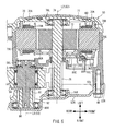
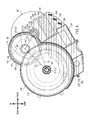
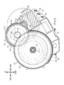
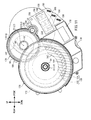
- FIG. 3 is a right side view of the driving unit 50 with the second housing portion 52R removed.
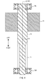
- FIG. 4 is a vertical cross-sectional view illustrating the positional relationship between the output shaft 74, rotor 72 and bearings 78L and 78R.
- the bus bars 80B are embedded in a support 80F, made of an insulating material (for example, a synthetic resin).
- the substrate 80C is supported by the support 80F.
- the support 80F is attached to the bobbins 70B.
- the detecting element 80D on the substrate 80C is positioned to face the detected portion 80A such that the detecting element and detected portion are arranged in an axial direction of the output shaft 74.
- the detecting element 80D detects rotation of the detected portion 80A by detecting changes in the magnetic field caused by the rotation of the detected portion 80A.
- the control device controls the rotation of the rotor 72. Wires (not shown) connecting the substrate 80C with the control device are connected with the connector 80E on the substrate 80C.
- the electric component 80 is not located between the bearing 88L and motor 60 along a line extending in an axial direction of the crankshaft 54.
- the bearing 88L and electric component 80 are located at different positions along the circumference around the central axis L2 of the output shaft 74. In other words, at least part of the bearing 88L and at least part of the electric component 80 overlap the motor 60 in different areas as viewed in an axial direction of the crankshaft 54.
- the bearing 88L is located at a different position than the bearing 68L as measured in an axial direction of the crankshaft 54.
- the bearing 88L is located at a different position than the bearing 68L as measured in an axial direction of the crankshaft 54" means that the bearing 88L does not overlap the bearing 68L when viewed in any direction perpendicular to the central axis L1 of the crankshaft 54.
- the bearing 88L is located between the bearings 68L and 68R as measured in an axial direction of the crankshaft 54.
- the bearing 88L is located closer to the bearing 68L than to the bearing 68R as measured in an axial direction of the crankshaft 54.
- the first line segment S1 connecting the rotational center C1 with the rotational center C2, the second line segment S2 connecting the rotational center C2 with the rotational center C3, and the third line segment S3 connecting the rotational center C3 with the rotational center C1 form a triangle.
- the first line segment S1 is longer than the second line segment S2 and longer than the third line segment S3.
- the first transmission gear 84 is made of a synthetic resin.
- the first transmission gear 84 is located on the transmission shaft 82.
- the first transmission gear 84 is located closer to the bearing 88R than to the bearing 88L as measured in an axial direction of the transmission shaft 82.
- the first transmission gear 84 engages the output gear 76.
- a one-way clutch 83 is provided between the first transmission gear 84 and the transmission shaft 82.
- the second transmission gear 86 is made of a metal material.
- the metal material may be iron, for example.
- the second transmission gear 86 is located on the transmission shaft 82.
- the second transmission gear 86 is located at a different position than the first transmission gear 84 as measured in an axial direction of the transmission shaft 82.
- the second transmission gear 86 is fixed to the transmission shaft 82 by spline fitting. That is, the second transmission gear 86 rotates together with the transmission shaft 82.
- the second transmission gear 86 is supported by the bearing 88R and is rotatable around the central axis L3 of the transmission shaft 82. That is, the second transmission gear 86 is located more distant from the bearing 88L than from the first transmission gear 84.
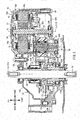
- FIG. 7 is an enlarged vertical cross-sectional view of portions of components shown in FIG. 2 .
- the rotating member 56 is positioned to be concentric with the crankshaft 54 and rotates together with the crankshaft 54.
- the rotating member 56 includes a connecting shaft 56A, torque detection device 56B and one-way clutch 56C.
- the torque detection device 56B is located inside the housing 52 (see FIG. 2 ).
- the torque detection device 56B is capable of detecting the torque generated in the crankshaft 54 when the rider operates the pedals 36R and 36L (see FIG. 1 ).
- the torque detection device 56B is a magnetostrictive torque sensor.
- the one-way clutch 56C is located closer to the driving sprocket 58 than to the torque detection device 56B, and is positioned to be concentric with the crankshaft 54.
- the one-way clutch 56C allows a rotational force that causes forward rotation of the crankshaft 54 to be transferred to the driving sprocket 58, while it prevents a rotational force that causes rearward rotation of the crankshaft 54 from being transferred to the driving sprocket 58.
- the body 108 has the shape of a ring.
- the crankshaft 54 is inserted through the body 108.
- the body 108 is positioned to be concentric with the crankshaft 54.
- Slide bearings 122 and 124 are located between the shaft portion 116 and crankshaft 54.
- the driven gear 104 is rotatable relative to the crankshaft 54.
- the shaft portion 116 includes a driven shaft 117 and an attachment shaft 118.
- the driven shaft 117 is located closer to the driving member 102 than to the attachment shaft 118, and is positioned to be concentric with the attachment shaft 118.
- the driven shaft 117 is formed integrally with the attachment shaft 118.
- the one-way clutch 56C allows a rotational force that is to cause forward rotation of the driving sprocket 58 about the central axis L1 of the crankshaft 54 to be transferred to the driving sprocket 58, while it prevents a rotational force that is to cause rearward rotation of the driving sprocket 58 from being transferred to the driving sprocket 58.
- the driven gear 104 When viewed in an axial direction of the crankshaft 54, the driven gear 104 has a larger diameter than the motor 60 and has a larger diameter than the first transmission gear 84.
- the motor 60 has a larger diameter than the first transmission gear 84.
- the component with the largest diameter as viewed in an axial direction of the crankshaft 54 i.e. the first component
- the component with the second largest diameter i.e. the second component
- the component with the smallest diameter i.e. the third component is the first transmission gear.
- the cylindrical portion 138 extends in an axial direction of the crankshaft 54.
- the cylindrical portion 138 is fixed to the outer peripheral surface of the cylindrical portion 110.
- the cylindrical portion 138 may be fixed to the outer peripheral surface of the cylindrical portion 110 by press fitting or bonding, for example.
- the detecting element 134 is a one-chip hall IC that includes two detecting sub-elements. Thus, it is possible to detect transverse and longitudinal fields of the ring magnet 132. As such, it is possible to determine whether the ring magnet 132 is rotating forward or rearward.
- the substrate 150 is disposed along the overlay surfaces 53L and 53R of the first and second housing portions 52L and 52R. "The substrate 150 is disposed along the overlay surfaces 53L and 53R" means that one of the sides of the substrate 150 disposed in a thickness direction thereof coincides with the overlay surfaces 53L and 53R as measured in an axial direction of the crankshaft 54.
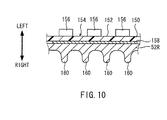
- the heat-transfer sheet 158 is in contact with the inner surface of the second housing portion 52R.
- the first region 154 is located on the inner surface of the second housing portion 52R with the heat-transfer sheet 158 in between.
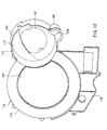
- the second partition portion 174 expands in directions perpendicular to the central axis L1 of the crankshaft 54. As shown in FIG. 3 , the second partition portion 174 is located at a different position than the first partition portion 172 as measured in an axial direction of the crankshaft 54. "The second partition portion 174 is located at a different position than the first partition portion 172 as measured in an axial direction of the crankshaft 54" means that the second partition portion 174 does not overlap the first partition portion 172 when viewed in any direction perpendicular to the central axis L1 of the crankshaft.
- the second partition portion 174 has two through-holes 182 and 184 formed therein.
- the through-hole 182 is larger than the through-hole 184 when viewed in an axial direction of the crankshaft 54.
- a torque is generated in the crankshaft 54.
- the torque generated in the crankshaft 54 is detected by the torque detection device 56B. If the torque generated in the crankshaft 54 continues to be above a predetermined reference value for a certain period of time or longer, the rotor 72 of the motor 60, i.e. the output shaft 74, rotates forward.
- the output gear 76 rotates forward.
- the first transmission gear 84 rotates rearward.
- the second transmission gear 86 rotates rearward.
- the driven gear 104 rotates forward.
- the attachment shaft 118 rotates forward.
- the driving sprocket 58 rotates forward. As a result, the rider is assisted in pedaling.
- the transmission shaft 82 extends parallel to a central axis L1 of the crankshaft 54.
- the substrate 150 includes a mounting surface 152 expanding in directions perpendicular to the central axis L1 of the crankshaft 54.
- the driving unit 50 further includes a housing 52.
- the housing 52 contains the motor 60, the first transmission gear 84, the driven gear 104 and the substrate 150. At least part of the region 154 is in contact with an inner surface of the housing 52.
- one of the first and second components 104 and 60 is the driven gear 104.
- the region 162 is a second region 162 overlapping the driven gear 104.
- a detecting element 134 for detecting rotation of the crankshaft 54 is provided on the second region 162.
Landscapes
- Engineering & Computer Science (AREA)
- Chemical & Material Sciences (AREA)
- Combustion & Propulsion (AREA)
- Transportation (AREA)
- Mechanical Engineering (AREA)
- Connection Of Motors, Electrical Generators, Mechanical Devices, And The Like (AREA)
Applications Claiming Priority (2)
| Application Number | Priority Date | Filing Date | Title |
|---|---|---|---|
| JP2012275111 | 2012-12-17 | ||
| JP2013073224A JP6168814B2 (ja) | 2013-03-29 | 2013-03-29 | 駆動ユニット及び電動補助自転車 |
Publications (2)
| Publication Number | Publication Date |
|---|---|
| EP2743169A1 true EP2743169A1 (de) | 2014-06-18 |
| EP2743169B1 EP2743169B1 (de) | 2019-07-17 |
Family
ID=49884931
Family Applications (1)
| Application Number | Title | Priority Date | Filing Date |
|---|---|---|---|
| EP13197042.8A Active EP2743169B1 (de) | 2012-12-17 | 2013-12-13 | Antriebseinheit und elektrisch unterstütztes Fahrrad |
Country Status (3)
| Country | Link |
|---|---|
| EP (1) | EP2743169B1 (de) |
| CN (1) | CN104010936B (de) |
| WO (1) | WO2014097985A1 (de) |
Cited By (5)
| Publication number | Priority date | Publication date | Assignee | Title |
|---|---|---|---|---|
| WO2016067200A1 (en) * | 2014-10-31 | 2016-05-06 | Piaggio & C. S.P.A. | Propulsion unit for an electric pedal-assisted cycle and pedal-assisted cycle thereof |
| EP3239031A1 (de) * | 2016-04-28 | 2017-11-01 | Yamaha Hatsudoki Kabushiki Kaisha | Antriebseinheit und elektromotorunterstütztes fahrrad |
| US10661858B2 (en) | 2016-04-28 | 2020-05-26 | Yamaha Hatsudoki Kabushiki Kaisha | Electric-motor-assisted bicycle |
| US10933944B2 (en) | 2017-08-09 | 2021-03-02 | Yamaha Hatsudoki Kabushiki Kaisha | Drive unit and electrically assisted bicycle |
| US12589829B2 (en) | 2018-03-13 | 2026-03-31 | Panasonic Intellectual Property Management Co., Ltd. | Motor unit and electric bicycle |
Families Citing this family (4)
| Publication number | Priority date | Publication date | Assignee | Title |
|---|---|---|---|---|
| JP6442232B2 (ja) * | 2014-11-04 | 2018-12-19 | ヤマハ発動機株式会社 | 駆動ユニット及び電動補助自転車 |
| CN111372841B (zh) * | 2017-11-24 | 2022-09-20 | 松下知识产权经营株式会社 | 电动助力自行车的驱动单元及电动助力自行车 |
| JP7457911B2 (ja) * | 2018-11-07 | 2024-03-29 | パナソニックIpマネジメント株式会社 | モータユニット及び電動自転車 |
| JP7777787B2 (ja) * | 2021-09-29 | 2025-12-01 | パナソニックIpマネジメント株式会社 | モータユニット及び電動自転車 |
Citations (7)
| Publication number | Priority date | Publication date | Assignee | Title |
|---|---|---|---|---|
| CH237118A (fr) * | 1942-07-27 | 1945-03-31 | Bugatti Ettore | Dispositif de propulsion auxiliaire pour cycles, particuliérement mais non exclusivement pour bicyclettes. |
| EP0798204A1 (de) * | 1996-03-29 | 1997-10-01 | Honda Giken Kogyo Kabushiki Kaisha | Regenerierungs-Steuereinrichtung für Fahrrad mit Hilfsmotor |
| JPH1016872A (ja) * | 1996-07-03 | 1998-01-20 | Yamaha Motor Co Ltd | 電動補助車両 |
| EP1088752A2 (de) * | 1999-09-30 | 2001-04-04 | Honda Giken Kogyo Kabushiki Kaisha | Hilfsantriebsvorrichtung für Fahrzeug |
| JP2002154474A (ja) * | 2000-11-20 | 2002-05-28 | Honda Motor Co Ltd | 磁気検出型センサ |
| JP2008114851A (ja) * | 2008-01-04 | 2008-05-22 | Yamaha Motor Electronics Co Ltd | 電動自転車用駆動装置 |
| CN202529107U (zh) * | 2012-03-30 | 2012-11-14 | 乐荣工业股份有限公司 | 混合动力载具离合式驱动装置 |
Family Cites Families (3)
| Publication number | Priority date | Publication date | Assignee | Title |
|---|---|---|---|---|
| JP4079642B2 (ja) * | 2002-01-23 | 2008-04-23 | 松下電器産業株式会社 | 電動自転車のモータユニット |
| JP5202769B1 (ja) * | 2012-07-11 | 2013-06-05 | パナソニック株式会社 | 電動アシスト自転車 |
| EP2886435B1 (de) * | 2012-08-17 | 2017-04-19 | Panasonic Intellectual Property Management Co., Ltd. | Stromunterstütztes fahrrad |
-
2013
- 2013-12-13 CN CN201380004112.8A patent/CN104010936B/zh active Active
- 2013-12-13 WO PCT/JP2013/083452 patent/WO2014097985A1/ja not_active Ceased
- 2013-12-13 EP EP13197042.8A patent/EP2743169B1/de active Active
Patent Citations (7)
| Publication number | Priority date | Publication date | Assignee | Title |
|---|---|---|---|---|
| CH237118A (fr) * | 1942-07-27 | 1945-03-31 | Bugatti Ettore | Dispositif de propulsion auxiliaire pour cycles, particuliérement mais non exclusivement pour bicyclettes. |
| EP0798204A1 (de) * | 1996-03-29 | 1997-10-01 | Honda Giken Kogyo Kabushiki Kaisha | Regenerierungs-Steuereinrichtung für Fahrrad mit Hilfsmotor |
| JPH1016872A (ja) * | 1996-07-03 | 1998-01-20 | Yamaha Motor Co Ltd | 電動補助車両 |
| EP1088752A2 (de) * | 1999-09-30 | 2001-04-04 | Honda Giken Kogyo Kabushiki Kaisha | Hilfsantriebsvorrichtung für Fahrzeug |
| JP2002154474A (ja) * | 2000-11-20 | 2002-05-28 | Honda Motor Co Ltd | 磁気検出型センサ |
| JP2008114851A (ja) * | 2008-01-04 | 2008-05-22 | Yamaha Motor Electronics Co Ltd | 電動自転車用駆動装置 |
| CN202529107U (zh) * | 2012-03-30 | 2012-11-14 | 乐荣工业股份有限公司 | 混合动力载具离合式驱动装置 |
Cited By (8)
| Publication number | Priority date | Publication date | Assignee | Title |
|---|---|---|---|---|
| WO2016067200A1 (en) * | 2014-10-31 | 2016-05-06 | Piaggio & C. S.P.A. | Propulsion unit for an electric pedal-assisted cycle and pedal-assisted cycle thereof |
| US10392076B2 (en) | 2014-10-31 | 2019-08-27 | Piaggio & C. S.P.A | Propulsion unit for an electric pedal-assisted cycle and pedal-assisted cycle thereof |
| EP3239031A1 (de) * | 2016-04-28 | 2017-11-01 | Yamaha Hatsudoki Kabushiki Kaisha | Antriebseinheit und elektromotorunterstütztes fahrrad |
| CN107336789A (zh) * | 2016-04-28 | 2017-11-10 | 雅马哈发动机株式会社 | 驱动单元以及电动辅助自行车 |
| US9834278B2 (en) | 2016-04-28 | 2017-12-05 | Yamaha Hatsudoki Kabushiki Kaisha | Drive unit and electric-motor-assisted bicycle |
| US10661858B2 (en) | 2016-04-28 | 2020-05-26 | Yamaha Hatsudoki Kabushiki Kaisha | Electric-motor-assisted bicycle |
| US10933944B2 (en) | 2017-08-09 | 2021-03-02 | Yamaha Hatsudoki Kabushiki Kaisha | Drive unit and electrically assisted bicycle |
| US12589829B2 (en) | 2018-03-13 | 2026-03-31 | Panasonic Intellectual Property Management Co., Ltd. | Motor unit and electric bicycle |
Also Published As
| Publication number | Publication date |
|---|---|
| EP2743169B1 (de) | 2019-07-17 |
| CN104010936B (zh) | 2016-08-24 |
| CN104010936A (zh) | 2014-08-27 |
| WO2014097985A1 (ja) | 2014-06-26 |
Similar Documents
| Publication | Publication Date | Title |
|---|---|---|
| EP2783972B1 (de) | Antriebseinheit und elektrisch unterstütztes Fahrrad | |
| EP2743169B1 (de) | Antriebseinheit und elektrisch unterstütztes Fahrrad | |
| JP6168814B2 (ja) | 駆動ユニット及び電動補助自転車 | |
| EP2743168B1 (de) | Antriebseinheit und elektrisch unterstütztes Fahrrad | |
| EP2743167B1 (de) | Antriebseinheit und elektrisch unterstütztes Fahrrad | |
| JP6218167B2 (ja) | 駆動ユニット及び電動補助自転車 | |
| EP3239031B1 (de) | Antriebseinheit und elektromotorunterstütztes fahrrad | |
| EP3239028B1 (de) | Elektromotorunterstütztes fahrrad | |
| TWI473744B (zh) | Bicycle motor control unit and bicycle | |
| EP3239032B1 (de) | Antriebseinheit und elektromotorunterstütztes fahrrad | |
| TWI675779B (zh) | 驅動單元及電動輔助自行車 | |
| EP3882120B1 (de) | Kraftübertragungseinheit für elektrofahrräder und elektrofahrrad | |
| JP6918890B2 (ja) | 駆動ユニットおよび電動補助自転車 | |
| JP7763657B2 (ja) | 人力駆動車用のコンポーネント | |
| JP7732641B2 (ja) | 電動補助自転車用のドライブユニットおよび電動補助自転車 | |
| JP2026006620A (ja) | モータユニット及び電動自転車 | |
| TW202225010A (zh) | 用於人力車輛的發電機 |
Legal Events
| Date | Code | Title | Description |
|---|---|---|---|
| PUAI | Public reference made under article 153(3) epc to a published international application that has entered the european phase |
Free format text: ORIGINAL CODE: 0009012 |
|
| 17P | Request for examination filed |
Effective date: 20131213 |
|
| AK | Designated contracting states |
Kind code of ref document: A1 Designated state(s): AL AT BE BG CH CY CZ DE DK EE ES FI FR GB GR HR HU IE IS IT LI LT LU LV MC MK MT NL NO PL PT RO RS SE SI SK SM TR |
|
| AX | Request for extension of the european patent |
Extension state: BA ME |
|
| R17P | Request for examination filed (corrected) |
Effective date: 20140917 |
|
| RBV | Designated contracting states (corrected) |
Designated state(s): AL AT BE BG CH CY CZ DE DK EE ES FI FR GB GR HR HU IE IS IT LI LT LU LV MC MK MT NL NO PL PT RO RS SE SI SK SM TR |
|
| REG | Reference to a national code |
Ref country code: DE Ref legal event code: R079 Ref document number: 602013057852 Country of ref document: DE Free format text: PREVIOUS MAIN CLASS: B62M0006550000 Ipc: B62M0011020000 |
|
| GRAP | Despatch of communication of intention to grant a patent |
Free format text: ORIGINAL CODE: EPIDOSNIGR1 |
|
| STAA | Information on the status of an ep patent application or granted ep patent |
Free format text: STATUS: GRANT OF PATENT IS INTENDED |
|
| RIC1 | Information provided on ipc code assigned before grant |
Ipc: B62M 6/55 20100101ALI20190128BHEP Ipc: B62M 11/02 20060101AFI20190128BHEP |
|
| INTG | Intention to grant announced |
Effective date: 20190211 |
|
| RIN1 | Information on inventor provided before grant (corrected) |
Inventor name: TOYOTA, YUICHI Inventor name: ISHIKAWA, NORIYASU Inventor name: MATUMURA, DAISUKE |
|
| GRAS | Grant fee paid |
Free format text: ORIGINAL CODE: EPIDOSNIGR3 |
|
| GRAA | (expected) grant |
Free format text: ORIGINAL CODE: 0009210 |
|
| STAA | Information on the status of an ep patent application or granted ep patent |
Free format text: STATUS: THE PATENT HAS BEEN GRANTED |
|
| AK | Designated contracting states |
Kind code of ref document: B1 Designated state(s): AL AT BE BG CH CY CZ DE DK EE ES FI FR GB GR HR HU IE IS IT LI LT LU LV MC MK MT NL NO PL PT RO RS SE SI SK SM TR |
|
| REG | Reference to a national code |
Ref country code: GB Ref legal event code: FG4D |
|
| REG | Reference to a national code |
Ref country code: CH Ref legal event code: EP |
|
| REG | Reference to a national code |
Ref country code: IE Ref legal event code: FG4D |
|
| REG | Reference to a national code |
Ref country code: DE Ref legal event code: R096 Ref document number: 602013057852 Country of ref document: DE |
|
| REG | Reference to a national code |
Ref country code: AT Ref legal event code: REF Ref document number: 1155612 Country of ref document: AT Kind code of ref document: T Effective date: 20190815 |
|
| REG | Reference to a national code |
Ref country code: NL Ref legal event code: FP |
|
| REG | Reference to a national code |
Ref country code: LT Ref legal event code: MG4D |
|
| REG | Reference to a national code |
Ref country code: AT Ref legal event code: MK05 Ref document number: 1155612 Country of ref document: AT Kind code of ref document: T Effective date: 20190717 |
|
| PG25 | Lapsed in a contracting state [announced via postgrant information from national office to epo] |
Ref country code: SE Free format text: LAPSE BECAUSE OF FAILURE TO SUBMIT A TRANSLATION OF THE DESCRIPTION OR TO PAY THE FEE WITHIN THE PRESCRIBED TIME-LIMIT Effective date: 20190717 Ref country code: HR Free format text: LAPSE BECAUSE OF FAILURE TO SUBMIT A TRANSLATION OF THE DESCRIPTION OR TO PAY THE FEE WITHIN THE PRESCRIBED TIME-LIMIT Effective date: 20190717 Ref country code: LT Free format text: LAPSE BECAUSE OF FAILURE TO SUBMIT A TRANSLATION OF THE DESCRIPTION OR TO PAY THE FEE WITHIN THE PRESCRIBED TIME-LIMIT Effective date: 20190717 Ref country code: FI Free format text: LAPSE BECAUSE OF FAILURE TO SUBMIT A TRANSLATION OF THE DESCRIPTION OR TO PAY THE FEE WITHIN THE PRESCRIBED TIME-LIMIT Effective date: 20190717 Ref country code: BG Free format text: LAPSE BECAUSE OF FAILURE TO SUBMIT A TRANSLATION OF THE DESCRIPTION OR TO PAY THE FEE WITHIN THE PRESCRIBED TIME-LIMIT Effective date: 20191017 Ref country code: AT Free format text: LAPSE BECAUSE OF FAILURE TO SUBMIT A TRANSLATION OF THE DESCRIPTION OR TO PAY THE FEE WITHIN THE PRESCRIBED TIME-LIMIT Effective date: 20190717 Ref country code: PT Free format text: LAPSE BECAUSE OF FAILURE TO SUBMIT A TRANSLATION OF THE DESCRIPTION OR TO PAY THE FEE WITHIN THE PRESCRIBED TIME-LIMIT Effective date: 20191118 Ref country code: NO Free format text: LAPSE BECAUSE OF FAILURE TO SUBMIT A TRANSLATION OF THE DESCRIPTION OR TO PAY THE FEE WITHIN THE PRESCRIBED TIME-LIMIT Effective date: 20191017 |
|
| PGFP | Annual fee paid to national office [announced via postgrant information from national office to epo] |
Ref country code: NL Payment date: 20191219 Year of fee payment: 7 |
|
| PG25 | Lapsed in a contracting state [announced via postgrant information from national office to epo] |
Ref country code: GR Free format text: LAPSE BECAUSE OF FAILURE TO SUBMIT A TRANSLATION OF THE DESCRIPTION OR TO PAY THE FEE WITHIN THE PRESCRIBED TIME-LIMIT Effective date: 20191018 Ref country code: RS Free format text: LAPSE BECAUSE OF FAILURE TO SUBMIT A TRANSLATION OF THE DESCRIPTION OR TO PAY THE FEE WITHIN THE PRESCRIBED TIME-LIMIT Effective date: 20190717 Ref country code: IS Free format text: LAPSE BECAUSE OF FAILURE TO SUBMIT A TRANSLATION OF THE DESCRIPTION OR TO PAY THE FEE WITHIN THE PRESCRIBED TIME-LIMIT Effective date: 20191117 Ref country code: LV Free format text: LAPSE BECAUSE OF FAILURE TO SUBMIT A TRANSLATION OF THE DESCRIPTION OR TO PAY THE FEE WITHIN THE PRESCRIBED TIME-LIMIT Effective date: 20190717 Ref country code: AL Free format text: LAPSE BECAUSE OF FAILURE TO SUBMIT A TRANSLATION OF THE DESCRIPTION OR TO PAY THE FEE WITHIN THE PRESCRIBED TIME-LIMIT Effective date: 20190717 Ref country code: ES Free format text: LAPSE BECAUSE OF FAILURE TO SUBMIT A TRANSLATION OF THE DESCRIPTION OR TO PAY THE FEE WITHIN THE PRESCRIBED TIME-LIMIT Effective date: 20190717 |
|
| PG25 | Lapsed in a contracting state [announced via postgrant information from national office to epo] |
Ref country code: TR Free format text: LAPSE BECAUSE OF FAILURE TO SUBMIT A TRANSLATION OF THE DESCRIPTION OR TO PAY THE FEE WITHIN THE PRESCRIBED TIME-LIMIT Effective date: 20190717 |
|
| PG25 | Lapsed in a contracting state [announced via postgrant information from national office to epo] |
Ref country code: RO Free format text: LAPSE BECAUSE OF FAILURE TO SUBMIT A TRANSLATION OF THE DESCRIPTION OR TO PAY THE FEE WITHIN THE PRESCRIBED TIME-LIMIT Effective date: 20190717 Ref country code: PL Free format text: LAPSE BECAUSE OF FAILURE TO SUBMIT A TRANSLATION OF THE DESCRIPTION OR TO PAY THE FEE WITHIN THE PRESCRIBED TIME-LIMIT Effective date: 20190717 Ref country code: EE Free format text: LAPSE BECAUSE OF FAILURE TO SUBMIT A TRANSLATION OF THE DESCRIPTION OR TO PAY THE FEE WITHIN THE PRESCRIBED TIME-LIMIT Effective date: 20190717 Ref country code: DK Free format text: LAPSE BECAUSE OF FAILURE TO SUBMIT A TRANSLATION OF THE DESCRIPTION OR TO PAY THE FEE WITHIN THE PRESCRIBED TIME-LIMIT Effective date: 20190717 Ref country code: IT Free format text: LAPSE BECAUSE OF FAILURE TO SUBMIT A TRANSLATION OF THE DESCRIPTION OR TO PAY THE FEE WITHIN THE PRESCRIBED TIME-LIMIT Effective date: 20190717 |
|
| PG25 | Lapsed in a contracting state [announced via postgrant information from national office to epo] |
Ref country code: SM Free format text: LAPSE BECAUSE OF FAILURE TO SUBMIT A TRANSLATION OF THE DESCRIPTION OR TO PAY THE FEE WITHIN THE PRESCRIBED TIME-LIMIT Effective date: 20190717 Ref country code: SK Free format text: LAPSE BECAUSE OF FAILURE TO SUBMIT A TRANSLATION OF THE DESCRIPTION OR TO PAY THE FEE WITHIN THE PRESCRIBED TIME-LIMIT Effective date: 20190717 Ref country code: IS Free format text: LAPSE BECAUSE OF FAILURE TO SUBMIT A TRANSLATION OF THE DESCRIPTION OR TO PAY THE FEE WITHIN THE PRESCRIBED TIME-LIMIT Effective date: 20200224 Ref country code: CZ Free format text: LAPSE BECAUSE OF FAILURE TO SUBMIT A TRANSLATION OF THE DESCRIPTION OR TO PAY THE FEE WITHIN THE PRESCRIBED TIME-LIMIT Effective date: 20190717 |
|
| REG | Reference to a national code |
Ref country code: DE Ref legal event code: R097 Ref document number: 602013057852 Country of ref document: DE |
|
| PLBE | No opposition filed within time limit |
Free format text: ORIGINAL CODE: 0009261 |
|
| STAA | Information on the status of an ep patent application or granted ep patent |
Free format text: STATUS: NO OPPOSITION FILED WITHIN TIME LIMIT |
|
| PG2D | Information on lapse in contracting state deleted |
Ref country code: IS |
|
| REG | Reference to a national code |
Ref country code: CH Ref legal event code: PL |
|
| 26N | No opposition filed |
Effective date: 20200603 |
|
| REG | Reference to a national code |
Ref country code: BE Ref legal event code: MM Effective date: 20191231 |
|
| PG25 | Lapsed in a contracting state [announced via postgrant information from national office to epo] |
Ref country code: MC Free format text: LAPSE BECAUSE OF FAILURE TO SUBMIT A TRANSLATION OF THE DESCRIPTION OR TO PAY THE FEE WITHIN THE PRESCRIBED TIME-LIMIT Effective date: 20190717 Ref country code: SI Free format text: LAPSE BECAUSE OF FAILURE TO SUBMIT A TRANSLATION OF THE DESCRIPTION OR TO PAY THE FEE WITHIN THE PRESCRIBED TIME-LIMIT Effective date: 20190717 |
|
| GBPC | Gb: european patent ceased through non-payment of renewal fee |
Effective date: 20191213 |
|
| PG25 | Lapsed in a contracting state [announced via postgrant information from national office to epo] |
Ref country code: IE Free format text: LAPSE BECAUSE OF NON-PAYMENT OF DUE FEES Effective date: 20191213 Ref country code: LU Free format text: LAPSE BECAUSE OF NON-PAYMENT OF DUE FEES Effective date: 20191213 Ref country code: FR Free format text: LAPSE BECAUSE OF NON-PAYMENT OF DUE FEES Effective date: 20191231 Ref country code: GB Free format text: LAPSE BECAUSE OF NON-PAYMENT OF DUE FEES Effective date: 20191213 |
|
| PG25 | Lapsed in a contracting state [announced via postgrant information from national office to epo] |
Ref country code: BE Free format text: LAPSE BECAUSE OF NON-PAYMENT OF DUE FEES Effective date: 20191231 Ref country code: CH Free format text: LAPSE BECAUSE OF NON-PAYMENT OF DUE FEES Effective date: 20191231 Ref country code: LI Free format text: LAPSE BECAUSE OF NON-PAYMENT OF DUE FEES Effective date: 20191231 |
|
| PG25 | Lapsed in a contracting state [announced via postgrant information from national office to epo] |
Ref country code: CY Free format text: LAPSE BECAUSE OF FAILURE TO SUBMIT A TRANSLATION OF THE DESCRIPTION OR TO PAY THE FEE WITHIN THE PRESCRIBED TIME-LIMIT Effective date: 20190717 |
|
| PG25 | Lapsed in a contracting state [announced via postgrant information from national office to epo] |
Ref country code: HU Free format text: LAPSE BECAUSE OF FAILURE TO SUBMIT A TRANSLATION OF THE DESCRIPTION OR TO PAY THE FEE WITHIN THE PRESCRIBED TIME-LIMIT; INVALID AB INITIO Effective date: 20131213 Ref country code: MT Free format text: LAPSE BECAUSE OF FAILURE TO SUBMIT A TRANSLATION OF THE DESCRIPTION OR TO PAY THE FEE WITHIN THE PRESCRIBED TIME-LIMIT Effective date: 20190717 |
|
| REG | Reference to a national code |
Ref country code: NL Ref legal event code: MM Effective date: 20210101 |
|
| PG25 | Lapsed in a contracting state [announced via postgrant information from national office to epo] |
Ref country code: NL Free format text: LAPSE BECAUSE OF NON-PAYMENT OF DUE FEES Effective date: 20210101 |
|
| PG25 | Lapsed in a contracting state [announced via postgrant information from national office to epo] |
Ref country code: MK Free format text: LAPSE BECAUSE OF FAILURE TO SUBMIT A TRANSLATION OF THE DESCRIPTION OR TO PAY THE FEE WITHIN THE PRESCRIBED TIME-LIMIT Effective date: 20190717 |
|
| PGFP | Annual fee paid to national office [announced via postgrant information from national office to epo] |
Ref country code: DE Payment date: 20251211 Year of fee payment: 13 |