EP2743403A1 - Dispositif et procédé destinés à l'établissement d'un élément de fondation - Google Patents
Dispositif et procédé destinés à l'établissement d'un élément de fondation Download PDFInfo
- Publication number
- EP2743403A1 EP2743403A1 EP12008288.8A EP12008288A EP2743403A1 EP 2743403 A1 EP2743403 A1 EP 2743403A1 EP 12008288 A EP12008288 A EP 12008288A EP 2743403 A1 EP2743403 A1 EP 2743403A1
- Authority
- EP
- European Patent Office
- Prior art keywords
- mixing
- drilling tool
- base body
- mixing section
- soil material
- Prior art date
- Legal status (The legal status is an assumption and is not a legal conclusion. Google has not performed a legal analysis and makes no representation as to the accuracy of the status listed.)
- Granted
Links
- 238000000034 method Methods 0.000 title claims abstract description 11
- 238000005553 drilling Methods 0.000 claims abstract description 114
- 239000000463 material Substances 0.000 claims abstract description 60
- 239000002689 soil Substances 0.000 claims description 51
- XLYOFNOQVPJJNP-UHFFFAOYSA-N water Substances O XLYOFNOQVPJJNP-UHFFFAOYSA-N 0.000 claims description 3
- 238000010276 construction Methods 0.000 abstract 1
- 239000000725 suspension Substances 0.000 description 4
- 230000008878 coupling Effects 0.000 description 3
- 238000010168 coupling process Methods 0.000 description 3
- 238000005859 coupling reaction Methods 0.000 description 3
- 230000000694 effects Effects 0.000 description 2
- 238000002679 ablation Methods 0.000 description 1
- 238000004873 anchoring Methods 0.000 description 1
- 230000001419 dependent effect Effects 0.000 description 1
- 239000000945 filler Substances 0.000 description 1
- 230000003993 interaction Effects 0.000 description 1
- 238000004519 manufacturing process Methods 0.000 description 1
- 239000002184 metal Substances 0.000 description 1
Images

Classifications
-
- E—FIXED CONSTRUCTIONS
- E02—HYDRAULIC ENGINEERING; FOUNDATIONS; SOIL SHIFTING
- E02D—FOUNDATIONS; EXCAVATIONS; EMBANKMENTS; UNDERGROUND OR UNDERWATER STRUCTURES
- E02D3/00—Improving or preserving soil or rock, e.g. preserving permafrost soil
- E02D3/12—Consolidating by placing solidifying or pore-filling substances in the soil
- E02D3/126—Consolidating by placing solidifying or pore-filling substances in the soil and mixing by rotating blades
Definitions
- the invention relates to a device for creating a foundation element in the ground according to the preamble of claim 1, a drilling device according to the preamble of claim 13, a pile tube according to the preamble of claim 14 and a method for creating a foundation element in the ground according to the preamble of claim 15 ,
- the invention relates to a device with a pile tube and a drilling device, which has a drill pipe running within the pile tube, a Bohrwerkmaschine noticed for removing soil material and a mixing device for mixing the ablated soil material with a supplied, curable medium.
- the pile tube comprises a tubular base body and a mixing section arranged underneath, which has a larger outer diameter than the tubular base body.
- Such a device is particularly suitable for creating a foundation element in a body of water.
- the drilling device from which the invention is based comprises a rotationally drivable drill string, a drilling tool device for removing soil material inside and / or below a pile tube, which can be introduced into the soil as part of a foundation element and has a tubular base body and a mixing section arranged underneath, which has a larger outer diameter than the tubular base body, and a mixing device for mixing the removed soil material with a supplied, curable medium.
- the method is based on a method, in particular for creating a foundation element in a body of water, in which a pile tube with a tubular base body and a lower mixing section arranged below it, which has a larger outer diameter than the tubular base body, is introduced into the soil.
- Soil material within the cross section of the mixing section is removed by means of a rotationally driven Bohrtechnikmaschine Kunststoff, the soil material is mixed with a supplied, curable medium for forming a filling material and the pile tube is filled to produce the foundation element with the filling material.
- the invention also relates to a pile tube, which can be introduced into the soil to form a foundation element, comprising a tubular base body and a mixing section arranged below the tubular base body, in which removed soil material can be mixed with a supplied curable medium and which has a larger outer diameter than the tubular body.
- the invention has for its object to provide an apparatus and a method for creating a foundation element, which allow a particularly economical creation of a foundation element. Furthermore, it is an object of the invention to provide a pile tube which can be used for this purpose.
- the device is inventively characterized in that the Bohrwerkmaschinetician comprises at least one pivotally mounted on the drill string drilling tool, with which soil material within and / or below the mixing section in a radially above the tubular body projecting region is ablatable.
- the drilling device is inventively characterized in that the Bohrwerkmaschinetician comprises at least one pivotally mounted on the drill string drilling tool, with which soil material within and / or below the mixing section in a radially above the tubular body projecting region is ablatable.
- the pile tube is according to the invention characterized in that the mixing section has a Abtragsquerites, within which soil material with a rotatably drivable Bohrtechnikmaschine ist is ablatable and which comprises a radially above the tubular body protruding cross-sectional area.
- the method is characterized in that the soil material is removed with a drilling tool of the drilling tool device mounted pivotably on a drill pipe in an ablation cross section of the mixing section, which comprises a cross-sectional area protruding radially beyond the tubular base body.
- a basic idea of the invention is to create a borehole with a diameter which is larger than the diameter of the tubular base body of the pile tube by means of the boring device guided through the pile tube. Between the pile tube main body and the borehole wall thus arises a ring-shaped or cylindrical space, which can be filled with the curable filling material. In this way, a particularly stable anchoring of the pile tube is achieved in the soil.
- the foundation element formed of pile tube and filling material is particularly stable.
- a first aspect of the invention can be seen in mixing the soil material removed by means of the drilling device with a curable or settable medium and in this way producing the filling material for filling the pile pipe.
- the production of the filling material thus takes place within the pile tube, in particular in the mixing section and / or above the drilling tool device. It is therefore not necessary to initially elaborate the removed soil material and then refill the pile tube with a separately prepared filling material again.
- the boring respectively Dumping the pile pipe and producing the filling material can be done simultaneously.
- Another aspect of the invention is to use a pile tube having at its lower end a mixing section with an enlarged diameter.
- the mixing section preferably has approximately the same diameter as the removal cross section along which the soil material is removed with the drilling device.
- the soil material is removed with a separate drilling device, which can be fixed to the pile tube.
- the drilling device comprises at its lower end a Bohrwerkmaschine adopted with at least one rotatably drivable drilling tool for removing the soil material.
- the drilling tool is pivotally mounted on the drill string in order to increase the Abtragsquersammlung relative to the cross section of the pile tube main body, so to allow soil removal in a radially beyond the inner cross section of the pile tube main body area. After folding the drilling tool, the drilling tool can be completely withdrawn from the pile tube.
- the lower opening cross section of the mixing region that is to say the inner cross section of the mixing region at its lower end, is greater than the inner and / or outer cross section of the pile tube main body.
- the soil material within and / or below the mixing section is removed by means of at least one fold-out drilling tool in a region projecting radially beyond the pipe section of the pile tube.
- the removed soil material is mixed with a curable suspension.
- a filling material is formed, with which the pile tube and the space between the pile tube and the borehole wall are filled.
- the pile tube remains as part of the foundation element in the ground.
- the mixing device which is preferably arranged directly above the drilling tool device, ensures efficient mixing of the removed soil material with that preferably in the region of the drilling tool device and / or the mixing device supplied, curable medium.
- the drilling tool device preferably has a conveying device, for example a conveying plate, in order to convey the removed soil material upwards in the direction of the mixing device.
- the mixing device may have one or more rotationally driven mixing elements.
- actively driven mixing elements such as mixing blades or mixing plates, a particularly good mixing effect is achieved.
- the drilling tool device in a deployed state of the drilling tool has a diameter which is larger than an inner diameter of the tubular base body, and that the Bohrwerkmaschine adopted in a folded state of the drilling tool has a diameter which is smaller than the inner diameter of the tubular base body.
- the drilling tool device can be introduced through the tubular base body of the pile tube into the region of the mixing section or removed from the pile tube.
- a soil removal in a Abtragsquerites can be realized, which is greater than the inner cross section of the pile tube main body and preferably at least equal to the cross section of the mixing section.
- the foldable drilling tool can preferably be folded out into an annular, outer cross-sectional area of the mixing section, which lies radially outside the cross section of the base body.
- the mixing device has at least one mixing element, which is mounted pivotably on the drill pipe.
- the mixing element is preferably rotatably mounted about a horizontal pivot axis.
- the soil material and the supplied, curable medium can thus be mixed within a cross section of the mixing section which is larger than the cross section of the upper, tubular base body.
- the mixing element can preferably be folded out into an annular, outer cross-sectional area of the mixing section, which lies radially outside the cross section of the base body.
- the hinged drilling tool and the folding mixing element are coupled together. In this way, it is particularly easy to adjust an unfolded state of the drilling tool and mixing element together. Likewise drilling tool and mixing element can be folded together in this way.
- the unfolding of the drilling tool can be accomplished in particular by the fact that the drilling tool contacts the borehole bottom.
- the coupling element by means of which the hinged mixing element is connected to the hinged drilling tool, the mixing element can be folded out in a particularly simple manner together with the drilling tool.
- the unfolding can also be effected by centrifugal forces.
- the pile tube has a stop on which the drilling device can be axially supported.
- the stop is preferably formed in a lower region of the tubular base body of the pile tube and can be designed in particular as a stop ring.
- the stop may have a sliding surface on which a stop element of the drilling device slides along.
- the drilling device has a stop element for supporting on the pile tube.
- the stop element is preferably fixedly connected to the drill string of the drilling device and is rotatable together with the drill string.
- the stop surface formed on the stop element preferably slides along the sliding surface of the stop of the pile tube.
- the drilling tool is formed in the unfolded state for removing soil material below a tube wall of the mixing section.
- the drilling tool can thus be folded out so far that it extends below the pipe wall of the mixing section.
- the cross section of the mixing section can be cut free by the drilling tool device with the unfolded drilling tool. In this way, a pile tube or mixing section can be used without lower Abtragsimplantation. Due to the large removal cross section of the drilling device, which corresponds at least to the outer cross-section of the mixing section, the pile tube can also bring into the ground without rotational movement.
- the stability and robustness of the drilling tool device can be increased by having the drilling tool device, in addition to the at least one hinged drilling tool, at least one drilling tool fixedly attached to the drill pipe.
- the fixed drilling tool for removing soil material within an inner, circular Bohrqueritess and the hinged drilling tool for removing soil material in an outer, annular cross-sectional area is formed.
- the inner removal cross-section preferably corresponds approximately to the cross-section of the tubular base body and the outer, annular removal cross-section corresponds to the area of the mixing section which projects radially beyond the base body.
- the mixing section has an annular upper end face in which openings are formed through which the soil material mixed with the supplied curable medium passes from the mixing section into the tubular one Main body surrounding annular space is conductive.
- the mixing section can have lateral openings or openings in order to reliably anchor the mixing section and / or to introduce the filler material via the lateral openings into the annular space formed around the base body.
- the introduction of the filling material into the annular space around the tubular base body can be further improved in that the tubular base body has lateral openings.
- the lateral openings in the tubular base body are preferably formed at least in a lower portion of the tubular base body, but may also extend along substantially the entire length of the tubular base body.
- the mixing effect within the mixing section can be improved by providing at least one fixed mixing element on an inner wall of the mixing section is arranged.
- the mixing element may comprise, for example, a radially protruding protuberance or a sheet metal and may in particular be arranged in a coordinated manner to the position of the rotating mixing elements.
- the mixing element arranged on the inner wall is arranged below and / or above the rotating mixing element, so that particularly efficient mixing takes place in interaction with the rotating mixing element.
- Fixed and rotating mixing element may overlap radially.
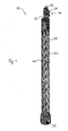
- the device 10 comprises a pile tube 20 with a separate drilling device 40 arranged thereon.
- the pile tube 20 comprises a tubular base body 22 and a mixing section 30 arranged at the lower end thereof.
- the mixing section 30 has a larger cross section or diameter As a result, when introducing the pile tube 20 into the ground around the tubular base body 22, an annular space 12 is formed, which extends between the tubular base body 22 and the borehole wall.
- the pile tube 20 is provided in the region of the base body 22 with a plurality of openings 24, to guide a filling material from the interior of the pile tube 20 into the outer annular space 12.
- the entire pile tube 20 with base body 22 and mixing section 30 is intended to remain as a support structure in the ground.
- the mixing section 30 likewise has a plurality of openings 32, 34, wherein upper openings 32 are provided on an upper, annular end surface 31 and lateral openings 34 are provided on a pipe wall 33. Through the upper and lateral openings 32, 34, a filling material can be efficiently introduced from the interior of the mixing section 30 into the annular space 12.
- the lateral openings 24 and 34 in the upper base body 22 and the lower mixing section 30 are in particular designed as elongated holes which extend in the longitudinal direction of the pile tube 20. Between the openings 34 in the mixing section 30 vertical webs 38 are formed, which separate the openings 34 from each other. On an inner side of the tube wall 33 of the mixing section 30, preferably in the region of the vertical webs 38, fixed mixing elements 36 are arranged, which may be formed as sheets.
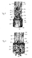
- a drilling device 40 For introducing the pile tube 20 into the ground, a drilling device 40 is provided, which is releasably secured to the pile tube 20.
- the drilling device 40 comprises a support frame 42, which can be placed on the pile tube 20 or in the Pile tube 20 can be fixed.
- a drive device 44 for rotating driving a drill pipe 46 is arranged on the support frame 42.
- the drilling device 40 comprises a suspension 43 with which the drilling device 40 can be lowered, for example by means of a cable, from a floating platform.
- a support structure or template placed on the floor can be used as support, which guides the pile tube 20.
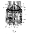
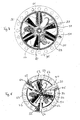
- the drilling device has at its lower end a drilling tool device 50, which comprises one or more fixed drilling tools 52, which are fastened to the drill pipe 46.
- the drilling tools 52 are dimensioned such that the drilling tool device 50 can be moved in the vertical direction through the base body 22 of the pile tube 20. Consequently, with the fixed drilling tools 52, soil material can only be removed in an inner region of the mixing section 30.
- the drilling tools 52 preferably comprise removal elements 53 arranged in the radial direction on a holding or baffle plate.
- one or more pivotable drilling tools 54 are provided.
- the pivotable drilling tools 54 are mounted on a base element 56 via a pivot joint 57 and can be pivoted about a horizontal axis of rotation relative to the drill pipe 46.
- the drilling tools 54 preferably comprise removal elements 55 exclusively in a radially outer area. By means of the pivotable drilling tools 54, soil can thus be removed in an outer, annular area.
- the pivotable drilling tools 54 are arranged immediately downstream of the fixed drilling tools 52 in the direction of rotation. In the operating position is a connecting web, which carries the radially outer Abtragswerkmaschinee 55 and connects with the pivot joint 57, in a Abtragsschatten the fixed drilling tool 52nd
- the mixing device 60 for mixing abraded soil material with a supplied curable medium.
- the mixing device 60 includes one or more fixed mixing elements 62 secured to the drill string 46 and a radial extent have, which is smaller than or equal to the inner diameter of the base body 22, so that the drill pipe 46 can be pulled out with the mixing elements 62 axially from the pile tube 20.
- the fixed mixing elements 62 may comprise, in particular, inclined mixing plates.
- pivotable mixing elements 64 are provided in addition to the fixed mixing elements 62.
- the pivotable mixing elements 64 are rotatably mounted about a pivot axis 67 on a base member 66 about a horizontal axis of rotation.
- the axes of rotation of the pivotable drilling tools 54 and the pivotable mixing elements 64 are parallel to each other.
- the coupling device 70 comprises a connection yoke with which a respective pivotable mixing element 64 is connected to a pivotable drilling tool 54.
- the connection yoke is pivoted both on the mixing element 64 and on the drilling tool 54.
- Drilling tools 54 and mixing elements 64 are pivotable in particular starting from their operating position downwards.
- the respective axes of rotation are arranged directly axially above one another.
- the drilling device 40 comprises a centering device 80, by means of which the drilling tool device 50 and / or the mixing device 60 is held within the mixing section 30 in a central position.
- the centering device 80 is fixedly connected to the drill pipe 46 and rotates together with this. It is supported radially on the main body 22 of the pile tube 20, so that the drill pipe 46 is held in the middle:
- a stop 48 is provided on the drilling device 40, by means of which the drill pipe 46 is held in a defined axial position.
- a further stop 28 is present, which in the present case is designed as a stop ring and on which the stop 48 is supported. In this way, the drilling device 40 sits on the stop 28 of the pile tube 20, so that a defined relative position of the drilling tool 50 is maintained to the pile tube 20.
- a centering or drill bit 58 is provided, which is arranged in the unfolded state of the drilling tool 54 in the direction of drilling ahead.
- a foundation element in the ground can be created particularly efficiently with the device according to the invention.
- a pile tube is introduced into the soil, soil material removed within the pile tube, mixed with a curable suspension and anchored the pile tube by means of the curable suspension in the ground.
Landscapes
- Engineering & Computer Science (AREA)
- Life Sciences & Earth Sciences (AREA)
- Structural Engineering (AREA)
- Agronomy & Crop Science (AREA)
- Environmental & Geological Engineering (AREA)
- Soil Sciences (AREA)
- General Life Sciences & Earth Sciences (AREA)
- Mining & Mineral Resources (AREA)
- Paleontology (AREA)
- Civil Engineering (AREA)
- General Engineering & Computer Science (AREA)
- Piles And Underground Anchors (AREA)
Priority Applications (3)
| Application Number | Priority Date | Filing Date | Title |
|---|---|---|---|
| EP12008288.8A EP2743403B1 (fr) | 2012-12-12 | 2012-12-12 | Dispositif et procédé destinés à l'établissement d'un élément de fondation |
| PCT/EP2013/073464 WO2014090490A1 (fr) | 2012-12-12 | 2013-11-11 | Dispositif et procédé pour ériger un élément de fondation |
| AU2013357721A AU2013357721B2 (en) | 2012-12-12 | 2013-11-11 | Device and method for creating a foundation element |
Applications Claiming Priority (1)
| Application Number | Priority Date | Filing Date | Title |
|---|---|---|---|
| EP12008288.8A EP2743403B1 (fr) | 2012-12-12 | 2012-12-12 | Dispositif et procédé destinés à l'établissement d'un élément de fondation |
Publications (2)
| Publication Number | Publication Date |
|---|---|
| EP2743403A1 true EP2743403A1 (fr) | 2014-06-18 |
| EP2743403B1 EP2743403B1 (fr) | 2015-03-25 |
Family
ID=47602719
Family Applications (1)
| Application Number | Title | Priority Date | Filing Date |
|---|---|---|---|
| EP12008288.8A Not-in-force EP2743403B1 (fr) | 2012-12-12 | 2012-12-12 | Dispositif et procédé destinés à l'établissement d'un élément de fondation |
Country Status (3)
| Country | Link |
|---|---|
| EP (1) | EP2743403B1 (fr) |
| AU (1) | AU2013357721B2 (fr) |
| WO (1) | WO2014090490A1 (fr) |
Citations (3)
| Publication number | Priority date | Publication date | Assignee | Title |
|---|---|---|---|---|
| EP1400633A2 (fr) * | 2002-09-19 | 2004-03-24 | Sigma Consult GmbH | Tête de forage |
| EP1491716A2 (fr) * | 2003-06-25 | 2004-12-29 | BAUER Maschinen GmbH | Méthode de forage et outil de forage humide |
| WO2008072950A2 (fr) * | 2006-12-13 | 2008-06-19 | Vertical Development B.V. | Système de fondation pour la formation d'un pieu de fondation dans le sol |
-
2012
- 2012-12-12 EP EP12008288.8A patent/EP2743403B1/fr not_active Not-in-force
-
2013
- 2013-11-11 WO PCT/EP2013/073464 patent/WO2014090490A1/fr not_active Ceased
- 2013-11-11 AU AU2013357721A patent/AU2013357721B2/en not_active Expired - Fee Related
Patent Citations (3)
| Publication number | Priority date | Publication date | Assignee | Title |
|---|---|---|---|---|
| EP1400633A2 (fr) * | 2002-09-19 | 2004-03-24 | Sigma Consult GmbH | Tête de forage |
| EP1491716A2 (fr) * | 2003-06-25 | 2004-12-29 | BAUER Maschinen GmbH | Méthode de forage et outil de forage humide |
| WO2008072950A2 (fr) * | 2006-12-13 | 2008-06-19 | Vertical Development B.V. | Système de fondation pour la formation d'un pieu de fondation dans le sol |
Also Published As
| Publication number | Publication date |
|---|---|
| EP2743403B1 (fr) | 2015-03-25 |
| AU2013357721B2 (en) | 2017-08-31 |
| WO2014090490A1 (fr) | 2014-06-19 |
| AU2013357721A1 (en) | 2015-06-11 |
Similar Documents
| Publication | Publication Date | Title |
|---|---|---|
| EP1640509B2 (fr) | Procédé et appareil pour creuser des tranchées dans le sol | |
| EP1310600B1 (fr) | Appareil et méthode de forage | |
| EP2295646B1 (fr) | Machine de forage et procédée | |
| EP2703564B1 (fr) | Cadre de guidage pour guider un dispositif de fraisage | |
| EP2562348B1 (fr) | Agencement de forage sous-marin et procédé d'exécution d'un forage | |
| DE2726445B2 (de) | Streckenvortriebsmaschine | |
| EP2322724A1 (fr) | Installation de forage d'eau souterraine et procédé d'entrée d'un élément de fondation cylindrique au fond de l'eau | |
| EP0293584A1 (fr) | Dispositif de forage pour méthode de forage par injection à haute pression | |
| EP1849919B1 (fr) | Engin de forage et méthode de construction d'une colonne forée dans le sol | |
| EP2423388A1 (fr) | Procédé et dispositif de fabrication d'une paroi moulée | |
| EP2246482B1 (fr) | Procédé et dispositif d'établissement d'un élément de fondation à friction partiellement réduite | |
| EP2743403B1 (fr) | Dispositif et procédé destinés à l'établissement d'un élément de fondation | |
| WO2014032847A1 (fr) | Dispositif de forage et procédé de forage | |
| DE3728270C2 (fr) | ||
| EP2730703B1 (fr) | Procédé et dispositif destinés à l'établissement d'un élément de fondation | |
| WO2015022105A1 (fr) | Procédé et dispositif de mise en place d'un élément de fondation dans le sol | |
| DE19533014A1 (de) | Verfahren zur Herstellung von Rohrwänden oder gemischten Spundwänden mit Rohrtragbohlen | |
| EP2666911B1 (fr) | Procédé de fabrication d'une paroi en mortier fixée dans le sol | |
| EP2719832B1 (fr) | Tête de découpage | |
| EP1630299B1 (fr) | Procedée de renforcement du fondations par injection | |
| DE2805362A1 (de) | Vorrichtung zum tunnelbau, insbesondere fuer standfeste und inhomogene bodenverhaeltnisse | |
| EP4350119B1 (fr) | Dispositif de forage sous-marin et procédé de construction d'un tubage sous-marin | |
| EP3081699B1 (fr) | Appareil de travaux publics et procédé destiné à la réalisation d'un élément de fondation dans le sol | |
| EP3192927B1 (fr) | Dispositif et procede de fabrication d'une colonne de remplissage | |
| DE10150278B4 (de) | Verfahren und Vorrichtung zum Bodenstabilisieren |
Legal Events
| Date | Code | Title | Description |
|---|---|---|---|
| PUAI | Public reference made under article 153(3) epc to a published international application that has entered the european phase |
Free format text: ORIGINAL CODE: 0009012 |
|
| 17P | Request for examination filed |
Effective date: 20121212 |
|
| AK | Designated contracting states |
Kind code of ref document: A1 Designated state(s): AL AT BE BG CH CY CZ DE DK EE ES FI FR GB GR HR HU IE IS IT LI LT LU LV MC MK MT NL NO PL PT RO RS SE SI SK SM TR |
|
| AX | Request for extension of the european patent |
Extension state: BA ME |
|
| R17P | Request for examination filed (corrected) |
Effective date: 20140526 |
|
| RBV | Designated contracting states (corrected) |
Designated state(s): AL AT BE BG CH CY CZ DE DK EE ES FI FR GB GR HR HU IE IS IT LI LT LU LV MC MK MT NL NO PL PT RO RS SE SI SK SM TR |
|
| GRAJ | Information related to disapproval of communication of intention to grant by the applicant or resumption of examination proceedings by the epo deleted |
Free format text: ORIGINAL CODE: EPIDOSDIGR1 |
|
| GRAP | Despatch of communication of intention to grant a patent |
Free format text: ORIGINAL CODE: EPIDOSNIGR1 |
|
| RIC1 | Information provided on ipc code assigned before grant |
Ipc: E02D 3/12 20060101AFI20140930BHEP |
|
| INTG | Intention to grant announced |
Effective date: 20141024 |
|
| GRAS | Grant fee paid |
Free format text: ORIGINAL CODE: EPIDOSNIGR3 |
|
| GRAA | (expected) grant |
Free format text: ORIGINAL CODE: 0009210 |
|
| AK | Designated contracting states |
Kind code of ref document: B1 Designated state(s): AL AT BE BG CH CY CZ DE DK EE ES FI FR GB GR HR HU IE IS IT LI LT LU LV MC MK MT NL NO PL PT RO RS SE SI SK SM TR |
|
| REG | Reference to a national code |
Ref country code: GB Ref legal event code: FG4D Free format text: NOT ENGLISH |
|
| REG | Reference to a national code |
Ref country code: CH Ref legal event code: EP |
|
| REG | Reference to a national code |
Ref country code: IE Ref legal event code: FG4D Free format text: LANGUAGE OF EP DOCUMENT: GERMAN |
|
| REG | Reference to a national code |
Ref country code: DE Ref legal event code: R096 Ref document number: 502012002617 Country of ref document: DE Effective date: 20150507 |
|
| REG | Reference to a national code |
Ref country code: AT Ref legal event code: REF Ref document number: 717973 Country of ref document: AT Kind code of ref document: T Effective date: 20150515 |
|
| REG | Reference to a national code |
Ref country code: NL Ref legal event code: T3 |
|
| PG25 | Lapsed in a contracting state [announced via postgrant information from national office to epo] |
Ref country code: FI Free format text: LAPSE BECAUSE OF FAILURE TO SUBMIT A TRANSLATION OF THE DESCRIPTION OR TO PAY THE FEE WITHIN THE PRESCRIBED TIME-LIMIT Effective date: 20150325 Ref country code: SE Free format text: LAPSE BECAUSE OF FAILURE TO SUBMIT A TRANSLATION OF THE DESCRIPTION OR TO PAY THE FEE WITHIN THE PRESCRIBED TIME-LIMIT Effective date: 20150325 Ref country code: LT Free format text: LAPSE BECAUSE OF FAILURE TO SUBMIT A TRANSLATION OF THE DESCRIPTION OR TO PAY THE FEE WITHIN THE PRESCRIBED TIME-LIMIT Effective date: 20150325 Ref country code: HR Free format text: LAPSE BECAUSE OF FAILURE TO SUBMIT A TRANSLATION OF THE DESCRIPTION OR TO PAY THE FEE WITHIN THE PRESCRIBED TIME-LIMIT Effective date: 20150325 |
|
| REG | Reference to a national code |
Ref country code: LT Ref legal event code: MG4D |
|
| PG25 | Lapsed in a contracting state [announced via postgrant information from national office to epo] |
Ref country code: GR Free format text: LAPSE BECAUSE OF FAILURE TO SUBMIT A TRANSLATION OF THE DESCRIPTION OR TO PAY THE FEE WITHIN THE PRESCRIBED TIME-LIMIT Effective date: 20150626 Ref country code: RS Free format text: LAPSE BECAUSE OF FAILURE TO SUBMIT A TRANSLATION OF THE DESCRIPTION OR TO PAY THE FEE WITHIN THE PRESCRIBED TIME-LIMIT Effective date: 20150325 Ref country code: LV Free format text: LAPSE BECAUSE OF FAILURE TO SUBMIT A TRANSLATION OF THE DESCRIPTION OR TO PAY THE FEE WITHIN THE PRESCRIBED TIME-LIMIT Effective date: 20150325 |
|
| PG25 | Lapsed in a contracting state [announced via postgrant information from national office to epo] |
Ref country code: RO Free format text: LAPSE BECAUSE OF FAILURE TO SUBMIT A TRANSLATION OF THE DESCRIPTION OR TO PAY THE FEE WITHIN THE PRESCRIBED TIME-LIMIT Effective date: 20150325 Ref country code: CZ Free format text: LAPSE BECAUSE OF FAILURE TO SUBMIT A TRANSLATION OF THE DESCRIPTION OR TO PAY THE FEE WITHIN THE PRESCRIBED TIME-LIMIT Effective date: 20150325 Ref country code: PT Free format text: LAPSE BECAUSE OF FAILURE TO SUBMIT A TRANSLATION OF THE DESCRIPTION OR TO PAY THE FEE WITHIN THE PRESCRIBED TIME-LIMIT Effective date: 20150727 Ref country code: EE Free format text: LAPSE BECAUSE OF FAILURE TO SUBMIT A TRANSLATION OF THE DESCRIPTION OR TO PAY THE FEE WITHIN THE PRESCRIBED TIME-LIMIT Effective date: 20150325 Ref country code: SK Free format text: LAPSE BECAUSE OF FAILURE TO SUBMIT A TRANSLATION OF THE DESCRIPTION OR TO PAY THE FEE WITHIN THE PRESCRIBED TIME-LIMIT Effective date: 20150325 Ref country code: ES Free format text: LAPSE BECAUSE OF FAILURE TO SUBMIT A TRANSLATION OF THE DESCRIPTION OR TO PAY THE FEE WITHIN THE PRESCRIBED TIME-LIMIT Effective date: 20150325 |
|
| PG25 | Lapsed in a contracting state [announced via postgrant information from national office to epo] |
Ref country code: IS Free format text: LAPSE BECAUSE OF FAILURE TO SUBMIT A TRANSLATION OF THE DESCRIPTION OR TO PAY THE FEE WITHIN THE PRESCRIBED TIME-LIMIT Effective date: 20150725 Ref country code: PL Free format text: LAPSE BECAUSE OF FAILURE TO SUBMIT A TRANSLATION OF THE DESCRIPTION OR TO PAY THE FEE WITHIN THE PRESCRIBED TIME-LIMIT Effective date: 20150325 |
|
| REG | Reference to a national code |
Ref country code: FR Ref legal event code: PLFP Year of fee payment: 4 |
|
| REG | Reference to a national code |
Ref country code: DE Ref legal event code: R097 Ref document number: 502012002617 Country of ref document: DE |
|
| PG25 | Lapsed in a contracting state [announced via postgrant information from national office to epo] |
Ref country code: DK Free format text: LAPSE BECAUSE OF FAILURE TO SUBMIT A TRANSLATION OF THE DESCRIPTION OR TO PAY THE FEE WITHIN THE PRESCRIBED TIME-LIMIT Effective date: 20150325 |
|
| PLBE | No opposition filed within time limit |
Free format text: ORIGINAL CODE: 0009261 |
|
| STAA | Information on the status of an ep patent application or granted ep patent |
Free format text: STATUS: NO OPPOSITION FILED WITHIN TIME LIMIT |
|
| 26N | No opposition filed |
Effective date: 20160105 |
|
| PG25 | Lapsed in a contracting state [announced via postgrant information from national office to epo] |
Ref country code: IT Free format text: LAPSE BECAUSE OF FAILURE TO SUBMIT A TRANSLATION OF THE DESCRIPTION OR TO PAY THE FEE WITHIN THE PRESCRIBED TIME-LIMIT Effective date: 20150325 |
|
| PG25 | Lapsed in a contracting state [announced via postgrant information from national office to epo] |
Ref country code: SI Free format text: LAPSE BECAUSE OF FAILURE TO SUBMIT A TRANSLATION OF THE DESCRIPTION OR TO PAY THE FEE WITHIN THE PRESCRIBED TIME-LIMIT Effective date: 20150325 |
|
| PGFP | Annual fee paid to national office [announced via postgrant information from national office to epo] |
Ref country code: FR Payment date: 20151230 Year of fee payment: 4 |
|
| PG25 | Lapsed in a contracting state [announced via postgrant information from national office to epo] |
Ref country code: MC Free format text: LAPSE BECAUSE OF FAILURE TO SUBMIT A TRANSLATION OF THE DESCRIPTION OR TO PAY THE FEE WITHIN THE PRESCRIBED TIME-LIMIT Effective date: 20150325 Ref country code: LU Free format text: LAPSE BECAUSE OF FAILURE TO SUBMIT A TRANSLATION OF THE DESCRIPTION OR TO PAY THE FEE WITHIN THE PRESCRIBED TIME-LIMIT Effective date: 20151212 |
|
| REG | Reference to a national code |
Ref country code: CH Ref legal event code: PL |
|
| REG | Reference to a national code |
Ref country code: IE Ref legal event code: MM4A |
|
| PG25 | Lapsed in a contracting state [announced via postgrant information from national office to epo] |
Ref country code: LI Free format text: LAPSE BECAUSE OF NON-PAYMENT OF DUE FEES Effective date: 20151231 Ref country code: CH Free format text: LAPSE BECAUSE OF NON-PAYMENT OF DUE FEES Effective date: 20151231 Ref country code: IE Free format text: LAPSE BECAUSE OF NON-PAYMENT OF DUE FEES Effective date: 20151212 |
|
| PGFP | Annual fee paid to national office [announced via postgrant information from national office to epo] |
Ref country code: NL Payment date: 20161221 Year of fee payment: 5 |
|
| PGFP | Annual fee paid to national office [announced via postgrant information from national office to epo] |
Ref country code: BE Payment date: 20161221 Year of fee payment: 5 |
|
| PGFP | Annual fee paid to national office [announced via postgrant information from national office to epo] |
Ref country code: DE Payment date: 20161227 Year of fee payment: 5 |
|
| PG25 | Lapsed in a contracting state [announced via postgrant information from national office to epo] |
Ref country code: SM Free format text: LAPSE BECAUSE OF FAILURE TO SUBMIT A TRANSLATION OF THE DESCRIPTION OR TO PAY THE FEE WITHIN THE PRESCRIBED TIME-LIMIT Effective date: 20150325 Ref country code: BG Free format text: LAPSE BECAUSE OF FAILURE TO SUBMIT A TRANSLATION OF THE DESCRIPTION OR TO PAY THE FEE WITHIN THE PRESCRIBED TIME-LIMIT Effective date: 20150325 Ref country code: NO Free format text: LAPSE BECAUSE OF FAILURE TO SUBMIT A TRANSLATION OF THE DESCRIPTION OR TO PAY THE FEE WITHIN THE PRESCRIBED TIME-LIMIT Effective date: 20150625 Ref country code: HU Free format text: LAPSE BECAUSE OF FAILURE TO SUBMIT A TRANSLATION OF THE DESCRIPTION OR TO PAY THE FEE WITHIN THE PRESCRIBED TIME-LIMIT; INVALID AB INITIO Effective date: 20121212 |
|
| PG25 | Lapsed in a contracting state [announced via postgrant information from national office to epo] |
Ref country code: CY Free format text: LAPSE BECAUSE OF FAILURE TO SUBMIT A TRANSLATION OF THE DESCRIPTION OR TO PAY THE FEE WITHIN THE PRESCRIBED TIME-LIMIT Effective date: 20150325 |
|
| GBPC | Gb: european patent ceased through non-payment of renewal fee |
Effective date: 20161212 |
|
| PG25 | Lapsed in a contracting state [announced via postgrant information from national office to epo] |
Ref country code: MT Free format text: LAPSE BECAUSE OF FAILURE TO SUBMIT A TRANSLATION OF THE DESCRIPTION OR TO PAY THE FEE WITHIN THE PRESCRIBED TIME-LIMIT Effective date: 20150325 |
|
| REG | Reference to a national code |
Ref country code: FR Ref legal event code: ST Effective date: 20170831 |
|
| PG25 | Lapsed in a contracting state [announced via postgrant information from national office to epo] |
Ref country code: FR Free format text: LAPSE BECAUSE OF NON-PAYMENT OF DUE FEES Effective date: 20170102 |
|
| PG25 | Lapsed in a contracting state [announced via postgrant information from national office to epo] |
Ref country code: GB Free format text: LAPSE BECAUSE OF NON-PAYMENT OF DUE FEES Effective date: 20161212 |
|
| PG25 | Lapsed in a contracting state [announced via postgrant information from national office to epo] |
Ref country code: MK Free format text: LAPSE BECAUSE OF FAILURE TO SUBMIT A TRANSLATION OF THE DESCRIPTION OR TO PAY THE FEE WITHIN THE PRESCRIBED TIME-LIMIT Effective date: 20150325 |
|
| REG | Reference to a national code |
Ref country code: DE Ref legal event code: R119 Ref document number: 502012002617 Country of ref document: DE |
|
| REG | Reference to a national code |
Ref country code: NL Ref legal event code: MM Effective date: 20180101 |
|
| PG25 | Lapsed in a contracting state [announced via postgrant information from national office to epo] |
Ref country code: NL Free format text: LAPSE BECAUSE OF NON-PAYMENT OF DUE FEES Effective date: 20180101 |
|
| REG | Reference to a national code |
Ref country code: BE Ref legal event code: MM Effective date: 20171231 |
|
| PG25 | Lapsed in a contracting state [announced via postgrant information from national office to epo] |
Ref country code: AL Free format text: LAPSE BECAUSE OF FAILURE TO SUBMIT A TRANSLATION OF THE DESCRIPTION OR TO PAY THE FEE WITHIN THE PRESCRIBED TIME-LIMIT Effective date: 20150325 Ref country code: TR Free format text: LAPSE BECAUSE OF FAILURE TO SUBMIT A TRANSLATION OF THE DESCRIPTION OR TO PAY THE FEE WITHIN THE PRESCRIBED TIME-LIMIT Effective date: 20150325 Ref country code: DE Free format text: LAPSE BECAUSE OF NON-PAYMENT OF DUE FEES Effective date: 20180703 |
|
| PG25 | Lapsed in a contracting state [announced via postgrant information from national office to epo] |
Ref country code: BE Free format text: LAPSE BECAUSE OF NON-PAYMENT OF DUE FEES Effective date: 20171231 |
|
| REG | Reference to a national code |
Ref country code: AT Ref legal event code: MM01 Ref document number: 717973 Country of ref document: AT Kind code of ref document: T Effective date: 20171212 |
|
| PG25 | Lapsed in a contracting state [announced via postgrant information from national office to epo] |
Ref country code: AT Free format text: LAPSE BECAUSE OF NON-PAYMENT OF DUE FEES Effective date: 20171212 |