EP2744190B1 - Drucksteuerungsvorrichtung und Verfahren zur Farbüberarbeitung - Google Patents
Drucksteuerungsvorrichtung und Verfahren zur Farbüberarbeitung Download PDFInfo
- Publication number
- EP2744190B1 EP2744190B1 EP13194986.9A EP13194986A EP2744190B1 EP 2744190 B1 EP2744190 B1 EP 2744190B1 EP 13194986 A EP13194986 A EP 13194986A EP 2744190 B1 EP2744190 B1 EP 2744190B1
- Authority
- EP
- European Patent Office
- Prior art keywords
- colour
- color
- feature information
- image forming
- forming apparatus
- Prior art date
- Legal status (The legal status is an assumption and is not a legal conclusion. Google has not performed a legal analysis and makes no representation as to the accuracy of the status listed.)
- Not-in-force
Links
Images


Classifications
-
- G—PHYSICS
- G06—COMPUTING OR CALCULATING; COUNTING
- G06F—ELECTRIC DIGITAL DATA PROCESSING
- G06F3/00—Input arrangements for transferring data to be processed into a form capable of being handled by the computer; Output arrangements for transferring data from processing unit to output unit, e.g. interface arrangements
- G06F3/12—Digital output to print unit, e.g. line printer, chain printer
-
- G—PHYSICS
- G06—COMPUTING OR CALCULATING; COUNTING
- G06K—GRAPHICAL DATA READING; PRESENTATION OF DATA; RECORD CARRIERS; HANDLING RECORD CARRIERS
- G06K15/00—Arrangements for producing a permanent visual presentation of the output data, e.g. computer output printers
- G06K15/02—Arrangements for producing a permanent visual presentation of the output data, e.g. computer output printers using printers
- G06K15/18—Conditioning data for presenting it to the physical printing elements
- G06K15/1801—Input data handling means
- G06K15/1802—Receiving generic data, e.g. fonts, colour palettes
-
- G—PHYSICS
- G06—COMPUTING OR CALCULATING; COUNTING
- G06F—ELECTRIC DIGITAL DATA PROCESSING
- G06F15/00—Digital computers in general; Data processing equipment in general
- G06F15/16—Combinations of two or more digital computers each having at least an arithmetic unit, a program unit and a register, e.g. for a simultaneous processing of several programs
-
- H—ELECTRICITY
- H04—ELECTRIC COMMUNICATION TECHNIQUE
- H04N—PICTORIAL COMMUNICATION, e.g. TELEVISION
- H04N1/00—Scanning, transmission or reproduction of documents or the like, e.g. facsimile transmission; Details thereof
- H04N1/00127—Connection or combination of a still picture apparatus with another apparatus, e.g. for storage, processing or transmission of still picture signals or of information associated with a still picture
- H04N1/00278—Connection or combination of a still picture apparatus with another apparatus, e.g. for storage, processing or transmission of still picture signals or of information associated with a still picture with a printing apparatus, e.g. a laser beam printer
-
- H—ELECTRICITY
- H04—ELECTRIC COMMUNICATION TECHNIQUE
- H04N—PICTORIAL COMMUNICATION, e.g. TELEVISION
- H04N1/00—Scanning, transmission or reproduction of documents or the like, e.g. facsimile transmission; Details thereof
- H04N1/46—Colour picture communication systems
- H04N1/56—Processing of colour picture signals
- H04N1/60—Colour correction or control
-
- H—ELECTRICITY
- H04—ELECTRIC COMMUNICATION TECHNIQUE
- H04N—PICTORIAL COMMUNICATION, e.g. TELEVISION
- H04N1/00—Scanning, transmission or reproduction of documents or the like, e.g. facsimile transmission; Details thereof
- H04N1/46—Colour picture communication systems
- H04N1/56—Processing of colour picture signals
- H04N1/60—Colour correction or control
- H04N1/603—Colour correction or control controlled by characteristics of the picture signal generator or the picture reproducer
- H04N1/6052—Matching two or more picture signal generators or two or more picture reproducers
- H04N1/6055—Matching two or more picture signal generators or two or more picture reproducers using test pattern analysis
Definitions
- the present invention relates to a print controlling apparatus, an image forming apparatus, a method of color revising and computer-readable recording medium thereof, and more specifically, to a print controlling apparatus that can revise colors so as to have output features as desired by a user, an image forming apparatus, a method of revising colors and a computer-readable recording medium thereof.
- image forming apparatuses operate to print printing data generated at a print controlling apparatuses onto a recording medium.
- image forming apparatuses include a copy machine, a printer, a scanner, a facsimile or a multi-function peripheral (MFP) that implements the above functions of copying, printing, scanning, and faxing within one complex apparatus.
- MFP multi-function peripheral
- Image forming apparatuses have their own color features implemented according to manufacturers' recommendations or to specific product models. Color features may be characteristics of toner or ink used by each manufacturer or may be policy related with color matching.
- a user When a user exchanges a previously used image forming apparatus with a new image forming apparatus, he or she may be satisfied with the color features implemented in the new image forming apparatus. However, a user may want to keep color features of the previously used image forming apparatus while utilizing a new apparatus.
- conventional image forming apparatuses collect color information of the used image forming apparatus, and revise color matching (gamut mapping) of the new image forming apparatus using the collected color information.
- US2003/0090688 discloses an apparatus for forming correction data for printers in accordance with colour reproducing characteristics of a reference printer.
- EP 2 131 567 discloses a colour reproduction sharing method.
- the present general inventive concept provides a print controlling apparatus, an image forming apparatus, a color revising method and a computer-readable recording medium, according to which color revising is operated by utilizing specific information of prestored color features so that a user can have output features as he/she wants.
- a print controlling apparatus according to claim 1 and a color revising method according to claim 7.
- a print controlling apparatus including a storage to store a plurality of color feature information, an acquirer to acquire color feature information of a second image forming apparatus, a moderator to moderate color converting table of the first image forming apparatus by using the acquired color feature information and the plurality of color feature information stored in the storage, and a controller to perform printing jobs regarding the first image forming apparatus by using the moderated color converting table.
- the plurality of stored color feature information are an International Color Consortium (ICC) profile or a color converting table regarding each of the first and second image forming apparatuses, which are different from one another.
- the first and second image forming apparatuses have at least one difference in manufacturers, product class, and products.
- the print controlling apparatus may additionally include a communicating interface to communicate with the second image forming apparatus and a scanner.
- the acquirer may control the communicating interface to print the prestored color charts in the second image forming apparatus, and acquires the color feature information of the second image forming apparatus by using the received scan image, if the scan image corresponding to scanned charts printed by the second image forming apparatus is received through the communicating interface.
- the color charts may include a plurality of colors regarding each of achromatic colors, bright colors, skin colors, and color gamut boundary.
- the moderator may select a stored color feature information from among the plurality of stored color feature information that is most similar to the acquired color feature information, and may moderate the color converting table regarding the first image forming apparatus by using the selected color feature information and the acquired color feature information.
- the moderator may moderate the color converting table of the first image forming apparatus by combining color values of the selected color feature information and color values of the acquired color feature information regarding each of color ranges corresponding to a predetermined ratio.
- the moderator may moderate the color converting table of the first image forming apparatus by using color values of the acquired color feature information regarding color ranges included in the acquired color feature information or by using color values of the selected color feature information regarding color ranges excluded in the acquired color feature information.
- the print controlling apparatus may additionally include a user interface to display a user interface window including a first area displaying a matching degree as compared to the acquired color feature information regarding each of the plurality of stored color feature information and a second area receiving selection on one of the plurality of stored color feature information.
- the moderator may moderate the color converting table of the first image forming apparatus by using the selected color feature information on the second area and the acquired color feature information.
- an image forming apparatus which may include a storage to store a plurality of color feature information and color converting table, a communicating interface to transmit color charts to a different image forming apparatus, a scanner to scan color charts printed by the different image forming apparatus, a moderator to moderate the color converting table by using the scanned
- the plurality of stored color feature information are an International Color Consortium (ICC) profile or a color converting table regarding each of the first and second image forming apparatuses, which are different from one another.
- ICC International Color Consortium
- a color revising method includes acquiring color feature information of a second image forming apparatus, selecting one from a plurality of prestored color feature information by using the acquired color feature information, and moderating a color converting table of the first image forming apparatus by using the selected color feature information and the acquired color feature information.
- the plurality of stored color feature information are an International Color Consortium (ICC) profile or a color converting table regarding each of the first and second image forming apparatuses, which are different from one another.
- ICC International Color Consortium
- the first and second image forming apparatuses have at least one difference in manufacturers, product class, and products.
- the color revising method may additionally include transmitting prestored color charts to the second image forming apparatus and receiving a scan image regarding scanned charts printed by the second image forming apparatus.
- the acquiring may acquire color feature information of the second image forming apparatus by using the received scan image.
- the color charts may include a plurality of colors regarding each of achromatic colors, bright colors, skin colors, and color gamut boundary.
- the moderating may moderate color converting table of the first image forming apparatus by combining color values of the selected color feature information and color values of the acquired color feature information regarding each of the plurality of color ranges on predetermined ratio.
- the moderating may moderate a color converting table of the first image forming apparatus by using color values of the acquired color feature information regarding color ranges included in the acquired color feature information, or by using color values of the selected color feature information regarding color ranges excluded by the acquired color feature information.
- the selecting may include displaying a matching degree with the acquired color feature information regarding each of the plurality of prestored color feature information and receiving a selection on one of the plurality of prestored color feature information.
- the color revising method may include acquiring color feature information of a second image forming apparatus, selecting one from a plurality of prestored color feature information by using the acquired color feature information, and moderating a color converting table of the first image forming apparatus by using the selected color feature information and the acquired color feature information.
- an image forming apparatus including a moderator to compare a scanned image from a second image forming apparatus with a plurality of prestored images within the image forming apparatus to moderate a color converting table of the image forming apparatus based on the comparison, and a controller to control the image forming apparatus to perform a printing operation based on the moderated color converting table.
- the moderator may select a prestored image from the plurality of prestored images that is most similar to the scanned image to combine color values of the selected prestored image and color values of the scanned image to perform the moderation of the color converting table of the image forming apparatus.
- the moderator may perform the comparison by comparing color feature information of at least a portion of the scanned image with color feature information of at least a portion of each of the plurality of prestored images.
- the color feature information may include at least one of an achromatic area, a bright area, skin colors, and a color gamut boundary.
- the image forming apparatus may further include an acquirer to acquire color feature information corresponding to the scanned image by extracting color values corresponding to a color chart from the scanned image, wherein the moderator compares the acquired color feature information to color feature information corresponding to the prestored images in order to perform the moderation of the color converting table.
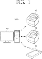
- FIG. 1 is a block diagram illustrating an image forming system 1000 according to an exemplary embodiment of the present general inventive concept.
- the image forming system 1000 may include a print controlling apparatus 100, a first image forming apparatus 10, a second image forming apparatus 20, and an image reading apparatus 30.
- the print controlling apparatus 100 receives a print command and generates printing data. Specifically, the print controlling apparatus 100 receives a print command corresponding to a document from a user, generates printing data corresponding to the document in response to the input print command, and transmits the generated printing data to the first and second image forming apparatuses 10 and 20. A structure and operations of the print controlling apparatus 100 will be explained below by referring to FIGS. 2 and 3 .
- the print controlling apparatus 100 may be a personal computer (PC), laptop computer, mobile phone, smart phone, portable media player (PMP), MP3 player, etc., but is not limited thereto.
- the first and second image forming apparatuses 10 and 20 receive the printing data from the print controlling apparatus 100, and print the received printing data. Specifically, the first and second image forming apparatuses 10 and 20 may receive printing data from the print controlling apparatus 100, and may perform printing jobs regarding the received printing data.
- the first and second image forming apparatuses 10 and 20 may be copy machines, printers, facsimiles, or multi-function peripherals (MFPs) that may implement the above functions of copying, printing and faxing via a single apparatus.
- MFPs multi-function peripherals
- the first image forming apparatus 10 is an operating image forming apparatus that performs color revising
- the second image forming apparatus 20 is an objective image forming apparatus that may receive printing data corresponding to the revised colors from the first image forming apparatus 10 in order to implement the revised colors. Accordingly, the second image forming apparatus 20 may receive scan charts from the print controlling apparatus 100 in order to print the scan charts.
- the image reading apparatus 30 scans a document and generates a scan image therefrom. Specifically, the image reading apparatus 30 may read scan charts printed by the second image forming apparatus 20, generate scan image, and transmit the generated scan image to the print controlling apparatus 100.
- the image reading apparatus 30 may be scanner, digital camera, spectrophotometer, etc., but is not limited thereto.
- the exemplary embodiment of the present general inventive concept according to FIG. 1 illustrates and describes that the image forming system 1000 includes the image reading apparatus 30 as a separate apparatus. However, if the first and second image forming apparatuses 10 and 20 are MFPs that can perform a scan function when implemented, the first and image forming apparatuses 10 and 20 may read scan charts printed by the second image forming apparatus 20 and may thereby generate a scan image.
- the above exemplary embodiment of the present general inventive concept according to FIG. 1 illustrates and describes that the print controlling apparatus 100 directly connects to the first and second image forming apparatuses 10 and 20, as well as the image reading apparatus 30.
- the print controlling apparatus 100 may be implemented to indirectly connect to the first and second image forming apparatuses 10 and 20 and the image reading apparatus 30 via a network created by a router and a server. Further, when implemented, each of the above-described apparatuses may be connected to each other wirelessly.
- FIG. 2 is a schematic block diagram of a print controlling apparatus according to an exemplary embodiment of the present general inventive concept.
- a print controlling apparatus 100 may include a storage 110, an acquirer 120, a moderator 130, and a controller 140.
- the storage 110 stores a plurality of color feature information or color feature values.
- Color feature information may include an International Color Consortium (ICC) profile or a color converting table.
- ICC International Color Consortium
- a plurality of color feature information prestored in the storage 110 may include an ICC profile or the color converting table, which are previously created by manufacturers of various image forming apparatuses on the market, specifically various image forming apparatuses having different manufacturers, product classes, or products.
- An ICC profile is a set of data that characterizes a color input or output device, or a color space, according to standards promulgated by the International Color Consortium (ICC). As such, characteristic colors of an original image may be implemented on color input and output devices regardless of color implementing features in the color input and output devices, and various image converting operations may be applied thereto.
- the ICC profile may correspond to a digital file that defines a relationship between a device-dependent color space and a device-independent color space in a format of mathematical modeling or a look-up table.
- the device-dependent color space is a color coordinate that expresses values of digital controlling signals in specific bit number, such as 8 bits or 10 bits, to define colors that are usable by color input and output devices.
- RGB, CMY and CMYK color spaces are typically used according to a method implementing colors of output devices and a number of primary colors.
- the device-dependent color space expresses only colors of color input and output devices with combinations of digital controlling signal values, natural colors as originally seen in nature cannot be reproduced.
- output image colors are shown differently, having different hues and intensities, for example.
- the device-independent color space is a color dimensional coordinate that quantifies and expresses color stimulus values that a human eye may perceive, and can reflect uniform color values regardless of color implementing features in color output devices.
- color coordinates such as sRGB, CIEXYZ, or CIELab are used.
- the storage 110 stores an image corresponding to color charts.
- Color charts are charts including a plurality of colors regarding each of achromatic colors, bright colors, skin colors, and color gamut boundary.
- An example of color charts is illustrated in FIG. 4 .
- FIG. 4 An example of color charts is illustrated in FIG. 4 .
- FIG. 4 Although the exemplary embodiment of the present general inventive concept describes that color charts of FIG. 4 are used, other types of color charts known to one of ordinary skill in the art may be used.
- the storage 110 may be a storage medium within the print controlling apparatus 100 or external storing medium, such as a hard drive, a removable disk including USB memory, or a web server through network.
- the acquirer 120 acquires color feature information of the second image forming apparatus 20. Specifically, the acquirer 20 may directly acquire an ICC profile or a color converting table of the second image forming apparatus 20. Further, the acquirer 120 may operate so that the color charts are printed by the second image forming apparatus 20, receive the scan image of the color charts printed by the second image forming apparatus 20, and acquire the color feature information of the second image forming apparatus 20 by utilizing the received scan image.
- the acquirer 120 may extract color values included in color charts from the scanned color charts, and generate RGB three-dimensional color matrix of the scanned color charts by using the extracted color values. As such, the acquirer 120 may generate RGB three-dimensional color matrix from the extracted color values by using regression technology.
- Regression technology is technology that infers undefined RGB color space by utilizing a plurality of color values. Since regression technology is well-known to one of ordinary skill in the art, detailed explanation thereof is not included herein.
- the acquirer 120 may generate an RGB three-dimensional color matrix regarding color feature information stored in the storage 110.
- the moderator 130 stores a color converting table of the first image forming apparatus 10.
- the color converting table is look-up table indicating converting values that can convert colors within an RGB color space to colors within a CMYK color space so as to implement colors within the RGB color space within printing data in an image forming apparatus that uses the CMYK color space. While the exemplary embodiment of the present general inventive concept only describes that color converting table to convert RGB color space to CMYK color space is used, a color converting table to convert color spaces other than the RGB color space to the CMYK color space may also be used.
- the color converting table of the second image forming apparatus 20 in the storage 110 may be renewed by the moderator 130, which will be explained below.
- the exemplary embodiment of the present general inventive concept describes that the color converting table is stored in the moderator 130, the color converting table may also be stored in the storage 110.
- the moderator 130 moderates the color converting table corresponding to the first image forming apparatus 10 by using the acquired color feature information and a plurality of color feature information stored in the storage 110. Specifically, the moderator 130 may select prestored color feature information that is most similar to the acquired color feature information from the plurality of prestored color feature information. Accordingly, the moderator 130 may compare each RGB three-dimensional color matrix of the plurality of prestored color feature information with an RBG three-dimensional color matrix of the acquired color feature information, and calculate similarities between the acquired color feature information regarding each of the plurality of prestored color feature information. The moderator 130 may select prestored color feature information having the highest similarity based on the calculated similarity.
- a display matching degree i.e., a similarity
- the acquired color feature information regarding each of the plurality of prestored color feature information may be displayed on a user interface window, and a user may select one of the plurality of color feature information.
- the moderator 130 may convert the color converting table corresponding to the first image forming apparatus 10 by using the selected color feature information. Specifically, the moderator 130 may convert the color converting table corresponding to the first image forming apparatus 10 by using the selected color feature information and/or the acquired color feature information using the above various methods.
- the moderator 130 may substitute the color converting table of the selected color feature information with the color converting table of the previous first image forming apparatus 10. Specifically, the moderator 130 may compare the RGB three-dimensional color matrix of the selected color feature information with the RGB three-dimensional color matrix of the color converting table corresponding to the first image forming apparatus 10 by using 3D-interpolation, and may redefine the RGB color mapping features of the first image forming apparatus 10 based on the comparison results so that RGB color values of color converting table corresponding to the first image forming apparatus 10 have color values of the selected color feature information. The moderator 130 may renew the color converting table of the first image forming apparatus 10 by using the redefined RGB color mapping features.
- the moderator 130 may moderate the color converting table of the first image forming apparatus 10 by combining color values of the selected prestored color feature information and the color values of the acquired color feature information corresponding to each of a plurality of color ranges at a predetermined ratio.
- the moderator 130 may combine the RGB three-dimensional color matrix of the selected color feature information and the RGB three-dimensional color matrix of the acquired color feature information at a predetermined ratio, specifically, corresponding to a default value or corresponding to a user selected value, compare the combined three-dimensional color matrix with the RGB three-dimensional color converting table of the color converting table corresponding to the first image forming apparatus 10, and redefine the RGB color mapping features of the first image forming apparatus 10 so that RGB color values of the color converting table regarding the first image forming apparatus 10 have color values of the combined RGB three-dimensional color matrix based on the comparison results.
- the moderator 130 may renew the color converting table of the first image forming apparatus 10 by using the redefined color mapping features.
- the moderator 130 may convert the color converting table of the first image forming apparatus 10 by using color values of the acquired color feature information regarding a color range included in the acquired color feature information or by using color values of the selected color feature information regarding a color range excluded in the acquired color feature information.
- the moderator 130 may generate the RGB three-dimensional color matrix by combining color values of the selected color feature information with the acquired color feature information corresponding to the user input ratio or the user setting, compare the generated RGB three-dimensional color matrix with the RGB three-dimensional color converting table of the color converting table corresponding to the first image forming apparatus 10, redefine the RGB color mapping features of the first image forming apparatus 10 so that RGB color values of the color converting table corresponding to the first image forming apparatus 10 have color values of the generated RGB three-dimensional color matrix based on the comparison results, and renew the color converting table of the first image forming apparatus 10 by using the redefined RGB color mapping features.
- the exemplary embodiment of the present general inventive concept describes that the acquirer 120 and the moderator 130 are separate units, the acquirer 120 and the moderator 130 may be formed within a single unit.
- the controller 140 controls each unit within the print controlling apparatus 100. Specifically, if a command to moderate color features is input by a user, the controller 140 controls printing color charts in the second image forming apparatus 20. If the scan image of the printed color charts is received from the second image forming apparatus 20, the controller 140 controls the acquirer 120 to acquire color feature information of the second image forming apparatus 20 by using the received scan image, and controls the moderator 130 to moderate the color converting table corresponding to the first image forming apparatus 10 by using the acquired color feature information and the prestored color feature information.
- controller 140 may perform printing jobs by utilizing the moderated color converting table.
- the print controlling apparatus 100 may include components other than those described above. A detailed description of the print controlling apparatus 100 will be explained below by referring to FIG. 3 .
- FIG. 3 is a detailed block diagram of a print controlling apparatus according to an exemplary embodiment of the present general inventive concept.
- a print controlling apparatus 100 may include a storage 110, an acquirer 120, a moderator 130, a controller 140, a communicating interface 150, a user interface 160, and a printer driver 170.
- the communicating interface 150 is connected to the first and second image forming apparatuses 10 and 20 and transmits printing data to the first and second image forming apparatuses 10 and 20. Specifically, the communicating interface 150 is formed to connect the print controlling apparatus 100 with external devices. Installation may be implemented by connecting to the first and second image forming apparatuses 10 and 20 through a universal serial bus (USB) port as well as a local area network and Internet network.
- USB universal serial bus
- the communicating interface 150 may transmit image corresponding to color charts (or printing data corresponding to color charts) to the second image forming apparatus 20.
- image corresponding to the color charts may be delivered by utilizing a portable-type storing medium (e.g., USB storing medium, external hard drive, etc.).
- the communicating interface 150 receives a scan image from the image reading apparatus 30. Specifically, the communicating interface 150 may receive the scan image corresponding to the color charts printed by the second image forming apparatus 20 from the image reading apparatus 30. If the first image forming apparatus 10 and the second image forming apparatus 20 are MFPs that can perform a scan function when implemented, a scan image corresponding to the printed color charts may be received from the first image forming apparatus 10 or the second image forming apparatus 20.
- the communicating interface 150 may transmit printing data generated in a driver 170, which will be explained below, to the first and second image forming apparatuses 10 and 20.
- the user interface (UI) 160 includes a plurality of function keys that a user may predefine, or the user may select various types of functions supported by the print controlling apparatus 100.
- the UI 160 also displays various types of information provided from the print controlling apparatus 100.
- the user interface 160 may be implemented as a device that simultaneously performs input and output functions, such as touch screen, or may alternatively be a device combined with a mouse and a monitor.
- a user may input a command to moderate color features via a user interface window provided by the user interface 160 so as to acquire an output from the second image forming apparatus 20.
- the printer driver 170 supports an interface between the print controlling apparatus 100 and the first and second image forming apparatuses 10 and 20, and converts data that a user tries to print into printing data, using a language format that the first and second image forming apparatuses 10 and 20 understand.
- the printer driver 170 may generate printing data by using the renewed color converting table.
- the controller 140 controls each unit within the print controlling apparatus 100. Specifically, if a command to moderate color features is input through the user interface 160, the controller 140 controls the printer driver 170 to print color charts in the second image forming apparatus 20. If the scan image of the color charts printed by the second image forming apparatus 20 is received through the communicating interface 150, the controller 140 controls the acquirer 120 to acquire color feature information of the second image forming apparatus 20 by using the received scan image, and controls the moderator 130 to moderate the color converting table of the first image forming apparatus 10 by using the acquired color feature information and the prestored color feature information.
- the print controlling apparatus 100 uses prestored color feature information while implementing color features of another image forming apparatus.
- data may be output in colors that are more accurate.
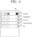
- FIG. 4 illustrates an example of color charts according to an exemplary embodiment of the present general inventive concept.
- color charts 400 include a first area 410 indicating achromatic colors, a second area 420 indicating bright colors, a third area 430 indicating skin colors, a fourth area 440 indicating a color gamut boundary and a fifth area 450 indicating extra colors.
- color feature information to be acquired from the second image forming apparatus 20 is provided to view color features within a main color implementing range, rather than to view overall color features of the second image forming apparatus 20.
- an objective of acquiring color feature information from the second image forming apparatus 20 is to acquire necessary information to substantiate differences between color features of an achromatic area, a bright area, skin colors, and a color gamut boundary, which have large differences in color features of image forming apparatuses. Therefore, the color charts according to an exemplary embodiment of the present general inventive concept include color values regarding areas having large differences in color features.
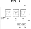
- FIGS. 5 and 6 illustrate various examples of a user interface window that can be displayed on a user interface.
- user interface window 500 includes a first area 510, a second area 520, an apply area 530, and a cancel area 540.
- the first area 510 is area that displays an image with reference to matching degrees of acquired color feature information corresponding to each of a plurality of stored color feature information. Specifically, the first area 510 is area that displays an image with regard to the colors moderated by the moderator 130, as described above.
- the second area 520 is area where one of a plurality of color feature information may selected by a user.
- the color feature information may be represented by radio buttons denoting a particular color percentage.
- the apply area 530 is area where a command to perform color revising may be input by using the color feature information selected in the second area 520.
- the cancel area 540 is area where a user command to cancel an operation of color revising may be input.
- FIG. 5 illustrates an example in which a predetermined percentage corresponding to color feature information to be applied is selected through a user interface window.
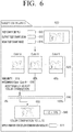
- a user may select combination degrees between the selected color feature information and the acquired color feature information via a different type of user interface window, as illustrated in FIG. 6 .
- a user interface window 600 includes a print output area 605, a scan area 610, a compare area 615, a similarity display area 620, a similarity result area 630, an adjust area 640, a preview area 650, a color difference display area 660 and an apply area 670.
- the print output area 605 is an area where a command to output color charts via the second image forming apparatus 20 is input. If the print output area 605 is selected, the print controlling apparatus 100 may transmit a prestored color chart image (or color chart printing data) to the second image forming apparatus 20.
- the scan area 610 is an area where a command to scan the printed color charts is input. If the scan area 610 is selected, the print controlling apparatus 100 may control the image reading apparatus 30 so that the color charts printed by the second image forming apparatus 20 can be scanned.
- the compare area 615 is an area where a command is received to perform a calculation of a similarity of the plurality of prestored color feature information and color feature information acquired from the scan image by using the scanned color charts. If the compare area 615 is selected, the print controlling apparatus 100 may determine similarity between each of the plurality of prestored color feature information and the acquired colors, and display determining results on the similarity display area 620 and the similarity result area 630 of the user interface window 600.
- the similarity display area 620 is an area where a similarity between each of the plurality of prestored color feature information and the acquired color feature information is displayed.
- the similarities may be represented by a percentage denoting an amount of similarity between the each of the plurality of prestored color feature information and the acquired color feature information.
- FIG. 6 illustrates that a Color B of the prestored color feature information has a 95% similarity to the acquired color feature information, while color A of the prestored color feature information has a 55% similarity to the acquired color feature.
- the Color B of the prestored color feature information has a closer similarity to the acquired color feature information than the Color A.
- the similarity result area 630 is an area where prestored color feature information having the highest (i.e., closest) similarity is displayed according to similarity results. As illustrated in FIG. 6 , the Color B of the prestored color feature information has a closest similarity to the acquired color feature information.
- the adjust area 640 is an area where a ratio of combining the selected color feature information and the acquired color feature information may be selected.
- the adjust area 640 may be implemented in a slide bar format as illustrated in FIG. 6 , or in a format which directly receives a combination ratio as input by a user.
- the preview area 650 is an area where a preview image corresponding to the color converting table generated according to the combination ratio selected in the adjust area 640 is displayed.
- the color difference display area 660 is an area where a difference between color feature information acquired according to the combination ratio selected in the adjust area 640 and the color feature information according to the combination results is displayed.
- the adjust area 670 is an area where a command to perform color revising according to the combination ratio selected in the adjust area 640 may be input.
- color converting table of the first image forming apparatus 10 may be stored and moderated in the print controlling apparatus 100, However, if the color converting table is stored in the image forming apparatus 10, the print controlling apparatus 100 may renew the color converting table and transmit the renewed color converting table to the first image forming apparatus 10. Further, the first image forming apparatus 10 can renew color converting table within itself.
- Such an exemplary embodiment of the present general inventive concept will be explained below by referring to FIG. 7 .
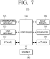
- FIG. 7 is a block diagram of an image forming apparatus 200 according to an exemplary embodiment of the present general inventive concept.
- the image forming apparatus 200 includes a communicating interface 210, a user interface 220, a storage 230, a scanner 240, an acquirer 250, a moderator 260, an image former 270 and a controller 280.
- the communicating interface 210 connects to the print controlling apparatus 100 and receives printing data from the print controlling apparatus 100. Specifically, the communicating interface 210 is formed to connect to the print controlling apparatus 100 with external devices. Connecting to the print controlling apparatus 100 can be performed through USB port as well as LAN or Internet network.
- the print controlling apparatus 100 connected to the image forming apparatus 200 may be the print controlling apparatus 100 illustrated in FIGS. 2 and 3 , or general print controlling apparatus 100 that does not include functions of FIGS. 2 and 3 .
- the communicating interface 210 may transmit an image corresponding to color charts to the print controlling apparatus 100 or to the second image forming apparatus 20.
- Color charts are charts including a plurality of colors regarding each of a plurality of achromatic colors, bright colors, skin colors, and a color gamut boundary.
- An example of color charts is illustrated in FIG. 4 .
- FIG. 4 An example of color charts is illustrated in FIG. 4 .
- the exemplary embodiment of the present general inventive concept only describes that color charts of FIG. 4 are used, the above-described color charts may be combined with color charts known to one of ordinary skill in the art.
- a carrying-type storing medium such as USB storing medium may be used to transmit the image corresponding to the color charts.
- the user interface 220 includes a plurality of function keys that a user can establish or select various types of functions supported by the image forming apparatus 200, and displays various types of information provided by the image forming apparatus 200.
- the user interface 220 may be implemented as a device that simultaneously performs an input and output, such as touch screen, or may be a device combining a mouse and a monitor. A user may input a command to begin color revising of the image forming apparatus 200 via a user interface window provided by the user interface 220.
- the storage 230 stores printing data. Specifically, the storage 230 may store printing data received from the above communicating interface 210.
- the storage 230 may be implemented as an external storing medium, such as a removable disk including USB memory, an external hard drive, and web server through a network, as well as an internal storing medium within the image forming apparatus 200.
- the storage 230 stores a plurality of color feature information.
- the color feature information may include an ICC profile or a color converting table and a plurality of color feature information prestored in the storage 230 may be an ICC profile or a color converting table that are previously created by manufacturers of various image forming apparatuses on the market, specifically various image forming apparatuses having different manufacturers, product classes, or products.
- the storage 230 stores the color converting table.
- the color converting table is a look-up table indicating converting values that can convert colors within an RGB color space to colors on a CMYK color space, so as to implement colors within the RGB color space within printing data in an image forming apparatus that uses the CMYK color space.
- Such a color converting table may be renewed by the moderator 260, which will be described below.
- the exemplary embodiment of the present general inventive concept only describes that the color converting table to convert the RGB color space to the CMYK color space is used. However, the color converting table may be used to convert other color spaces besides the RGB color space to CMYK color space.
- the storage 230 stores an image corresponding to color charts.
- the scanner 240 includes a lens forming lights reflecting from a document to an image on an internal image sensor, and reads image information of the document from the lights formed on the image sensor.
- the scanner 240 scans the color charts printed by the second image forming apparatus 20, and provides the scanned color charts to the acquirer 250.
- the scanner 240 may provide the image corresponding to the scanned color charts to the acquirer 250, or extract only color values included in the scanned color charts, and provide the color values to the acquirer 250.
- the scanner 240 may be mounted on a flatbed scanner system or within a Duplex Automatic Document Feeder (DADF).
- DADF Duplex Automatic Document Feeder
- the scanner 240 may convert at least one of color space, number, and color arrangement of the scanned color charts. Specifically, if the color charts scanned by the scanner 240 are not charts illustrated in FIG. 4 , the scanner 240 may convert the scanned color charts to be suitable to provide a color arrangement of the charts illustrated in FIG. 4 , while keeping color values of the scanned color charts. The scanner 240 may provide the converted color charts to the acquirer 250.
- color charts are directly scanned and used by the scanner 240 mounted within the image forming apparatus 200
- color charts may be scanned through external scan devices and the color charts scanned by external scan devices may be received by using the communicating interface 210.
- the acquirer 250 acquires color feature information of the second image forming apparatus 20. Specifically, the acquirer 250 may directly acquire ICC profile or color converting table of the second image forming apparatus 20. Further, the acquirer 250 may operate so that color charts are printed by the second image forming apparatus 20, receive the scan image of the color charts printed by the second image forming apparatus 20, and acquire the color feature information of the second image forming apparatus 20 by using the received scan image.
- the acquirer 250 may extract color values included in the color charts from the scanned color charts, and generate an RGB three-dimensional color matrix of the scanned color charts by using the extracted color values.
- the acquirer 250 may generate the RGB three-dimensional color matrix from the extracted color values by using regression technology.
- the acquirer 250 may generate RGB three-dimensional color matrix regarding color feature information stored in the storage 230.
- the moderator 260 converts a color converting table regarding the image forming apparatus 200 by using the acquired color feature information and the plurality of color feature information stored in the storage 230. Specifically, the moderator 260 may select prestored color feature information among the plurality of prestored color feature information compared that is most similar to the acquired color feature information. More specifically, the moderator 260 may compare each of the RGB three-dimensional color matrices regarding the plurality of prestored image forming apparatus with the RGB three-dimensional color matrix of the acquired color feature information, and calculate similarities between the acquired color feature information with respect to each of the plurality of prestored color feature information.
- the moderator 260 may select prestored color feature information having the highest similarity based on the calculated similarity. Furthermore, matching degrees (i.e., similarities) between the acquired color feature information with respect to each of the plurality of color feature information may be displayed on the user interface window, such that one of the plurality of color feature information may be selected from a user.
- the moderator 260 may convert the color converting table by using the selected color feature information. Specifically, the moderator 260 may convert the color feature table by using the selected color feature information and/or the acquired color feature information with various methods as described above.
- the moderator 260 may substitute the color converting table of the selected color feature information with a color converting table regarding the previous image forming apparatus 200.
- the moderator 260 may also convert the color converting table of the image forming apparatus 200 by combining color values of the selected color feature information and color values of the acquired color feature information regarding each of a plurality of color ranges with respect to a predetermined ratio. Further, the moderator 260 may convert the color converting table of the image forming apparatus 200 by using color values of the acquired color feature information regarding color ranges included in the acquired color feature information or color values of the selected color feature information regarding color ranges not included in the acquired color feature information.
- the exemplary embodiment of the present general inventive concept describes that the acquirer 250 and the moderator 260 are separate components, a single device including the acquirer 250 and the moderator 260 may be implemented.
- the image former 270 prints printing data. Specifically, the image former 270 may print printing data received through the communicating interface 210 by using the renewed color converting table.
- the controller 280 controls each component within the image forming apparatus 200. Specifically, if the user interface 220 receives a command to moderate color features from a user, the controller 280 may control the communicating interface 210 to print color charts in the second image forming apparatus 20, and control the scanner 240 to scan the color charts printed by the second image forming apparatus 20.
- the controller 280 may control the acquirer 250 to acquire color feature information of the second image forming apparatus 20 by using the received scan image, and control the moderator 260 to moderate the color converting table by using the acquired color feature information and prestored color feature information.
- the controller 280 may control the image former 270 to perform printing jobs by using the moderated color converting table.
- the image forming apparatus 200 uses prestored color feature information while implementing color features of another image forming apparatus, and thus, implements colors that are more accurate.
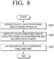
- FIG. 8 is a flowchart briefly explaining a color revising method according to an exemplary embodiment of the present general inventive concept.
- Color feature information of the second image forming apparatus 20 is acquired at S810. Specifically, an ICC profile or a color converting table of the second image forming apparatus 20 may be directly acquired, or, color charts may be printed by the image forming apparatus 20, a scan image of the color charts printed by the second image forming apparatus 20 may be received, and color feature information of the second image forming apparatus 20 may be acquired by using the received scan image.
- One prestored color feature information is selected from a plurality of prestored color feature information by using the acquired color feature information, and a color converting table regarding the first image forming apparatus is moderated by using the selected color feature information and the acquired color feature information at S820.
- a detailed operation of moderating the color converting table will be explained below by referring to FIG. 9 .
- Printing is performed by using the moderated color converting table at S830.
- the color revising method uses prestored color feature information while implementing color features of another image forming apparatus, and thus, implements colors that are more accurate.
- the color revising method of FIG. 8 may be implemented in a print controlling apparatus as illustrated in FIG. 2 or FIG. 3 , an image forming apparatus as illustrated in FIG. 7 , or a print controlling apparatus or an image forming apparatus having other embodiments not limited hereto.
- the present general inventive concept can also be embodied as computer-readable codes on a computer-readable medium.
- the computer-readable medium can include a computer-readable recording medium and a computer-readable transmission medium.
- the computer-readable recording medium is any data storage device that can store data that can be thereafter read by a computer system. Examples of the computer-readable recording medium include read-only memory (ROM), random-access memory (RAM), CD-ROMs, magnetic tapes, floppy disks, and optical data storage devices.
- the computer-readable recording medium can also be distributed over network coupled computer systems so that the computer-readable code is stored and executed in a distributed fashion.
- the computer-readable transmission medium can transmit carrier waves or signals (e.g., wired or wireless data transmission through the Internet). Also, functional programs, codes, and code segments to accomplish the present general inventive concept can be easily construed by programmers skilled in the art to which the present general inventive concept pertains.
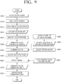
- FIG. 9 is a flowchart specifically explaining a color revising method according to an exemplary embodiment of the present general inventive concept.
- the second image forming apparatus 20 previously stores image of color charts to acquire color information at S905.
- the prestored color charts are printed by the second image forming apparatus 20 at S910. Specifically, image corresponding to the prestored color charts (or printing data) is transmitted to the second image forming apparatus 20.
- color charts printed by the second image forming apparatus 20 are scanned.
- the scanning of color charts may be performed in the separate image reading apparatus 30, the first image forming apparatus 10 including a scan function, or the second image forming apparatus 20.
- the scan image is received.
- color values of color charts are extracted at S925, and color feature information of the second image forming apparatus 20 is acquired based on the extracted color values at S930.
- color feature information to be applied is selected among the color feature information prestored at S935 regarding different image forming apparatuses. Such selecting may be performed automatically according to color similarity or by a user.
- option values of the selected color feature information and the acquired color feature information are selected. Specifically, a combination ratio may be selected via the slide bar within the adjust area 640, as illustrated in FIG. 6 .
- Color combination is performed based on the selected color feature information, the acquired color feature information and the selected option values at S950.
- An RGB three-dimensional color matrix to be applied in the first image forming apparatus 10 is generated. Detailed operation of the color combination will be explained below by referring to FIG. 10 .
- the color feature information at S960 of the first image forming apparatus 10 and the previously generated RGB three-dimensional color matrix are device-linked at S965, and the color converting table regarding the first image forming apparatus 10 is generated at S970.
- the previous color converting table is renewed by using the generated color converting table.
- the color revising method uses prestored color feature information while implementing color features of another image forming apparatus, and thus, implements colors that are more accurate.
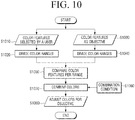
- FIG. 10 is a flowchart specifically explaining the color combining operation of FIG. 9 .
- the color combining operation is an operation to combine color features of an image forming apparatus to be pursued as objective and selected color features before producing color features to be applied in the first image forming apparatus 10, so as to implement colors that a user wants.
- Color features of an image forming apparatus to be pursued as objective basically show color features that a user wants to implement, and selected color features show representative color features of a manufacturer (e.g., a manufacturer of the second image forming apparatus 20) regarding color features that a user wants to implement.
- a manufacturer e.g., a manufacturer of the second image forming apparatus 20
- Such a combination contributes to an enhanced performance of implementing colors that a user wants.
- Selected color features are produced by considering color policies of manufacturers, which supplements parts that cannot be considered or may be insufficient in color features as objective.
- Color combination is not a simple combination of color features versus color features. Based on color features as objective, selected color features are compared with color features as objective, and an area having large differences in color and an area having small differences in color are divided. Thus, a user can adjust a degree of color combination.
- This is to supplement color features of the second image forming apparatus 20 by utilizing prestored color features. By supplementing color features, color features or policies of manufacturers or product classes that prestored color features include therein, may be reflected.
- color features selected by a user at S1010 are divided per color range at S1020, and color features as objective at S1030 are divided per color range at S1040.
- Each of the color features divided per range are compared at S1050, and according to a combination condition in each color range selected by a user at S1060, the color combination is performed at S1070. Adjusted objective color features are acquired at S1080.
Landscapes
- Engineering & Computer Science (AREA)
- Multimedia (AREA)
- Signal Processing (AREA)
- Theoretical Computer Science (AREA)
- General Engineering & Computer Science (AREA)
- General Physics & Mathematics (AREA)
- Physics & Mathematics (AREA)
- Computer Hardware Design (AREA)
- Human Computer Interaction (AREA)
- Software Systems (AREA)
- Color Image Communication Systems (AREA)
- Facsimile Image Signal Circuits (AREA)
- Image Processing (AREA)
- Record Information Processing For Printing (AREA)
- Accessory Devices And Overall Control Thereof (AREA)
Claims (8)
- Drucksteuerungsvorrichtung (100), die mit einer ersten Bilderzeugungsvorrichtung (10) verbunden werden kann, wobei die Drucksteuerungsvorrichtung Folgendes umfasst:einen Speicher (110) zum Vorspeichern mehrerer Farbmerkmalsinformationen;eine Erfassungseinrichtung (120) zum Erfassen von Farbmerkmalsinformationen einer zweiten Bilderzeugungsvorrichtung (20);eine Moderatoreinrichtung (130) zum Erneuern einer Farbumwandlungstabelle der ersten Bilderzeugungsvorrichtung unter Verwendung der erfassten Farbmerkmalsinformationen und der im Speicher vorgespeicherten mehreren Farbmerkmalsinformationen ;eine Steuervorrichtung (140) zum Steuern der ersten Bilderzeugungsvorrichtung, um Druckaufträge unter Verwendung der erneuerten Farbumwandlungstabelle durchzuführen; undeine Kommunikationsschnittstelle (150) zum Kommunizieren mit einem Scanner (30) und der zweiten Bilderzeugungsvorrichtung,wobei die Erfassungseinrichtung konfiguriert ist, die zweite Bilderzeugungsvorrichtung zu steuern, um vorgespeicherte Farbtafeln zu drucken, und die Farbmerkmalsinformationen der zweiten Bilderzeugungsvorrichtung unter Verwendung eines Abtastbildes der vorgespeicherten Farbtafeln zu erfassen, die durch die zweite Bilderzeugungsvorrichtung gedruckt werden, empfangen von dem Scanner durch die Kommunikationsschnittstelle,wobei die Moderatoreinrichtung angeordnet ist, Farbmerkmalsinformationen von den mehreren vorgespeicherten Farbmerkmalsinformationen auszuwählen, die den erfassten Farbmerkmalsinformationen am ähnlichsten sind, durch Vergleichen dreidimensionaler Farbmatrizen der mehreren vorgespeicherten Farbmerkmalsinformationen mit einer dreidimensionalen Farbmatrix, die aus den erfassten Farbmerkmalsinformationen erzeugt wurde, und angeordnet sind, die Farbumwandlungstabelle der ersten Bilderzeugungsvorrichtung unter Verwendung der ausgewählten Farbmerkmalsinformationen und der erfassten Farbmerkmalsinformationen zu erneuern,wobei die Farbmerkmalsinformationen ein Profil des International Colour Consortium, ICC, oder eine Farbumwandlungstabelle bezogen auf jede der ersten und der zweiten Bilderzeugungsvorrichtung umfassen, wobei die Farbumwandlungstabelle eine Nachschlagetabelle zum Umwandeln von Farben in einem ersten Farbraum in Farben in einem zweiten Farbraum ist.
- Drucksteuerungsvorrichtung nach Anspruch 1, wobei die erste und die zweite Bilderzeugungsvorrichtung wenigstens einen Unterschied bei Herstellern, Produktklasse und Produkten aufweisen.
- Drucksteuerungsvorrichtung nach Anspruch 2, wobei die Farbtafeln mehrere Farben bezogen sowohl auf achromatische Farben, helle Farben, Hautfarben als auch Farbumfangsgrenze enthalten.
- Drucksteuerungsvorrichtung nach einem der vorhergehenden Ansprüche, wobei die Moderatoreinrichtung angeordnet ist, die Farbumwandlungstabelle der ersten Bilderzeugungsvorrichtung durch Kombinieren von Farbwerten der ausgewählten Farbmerkmalsinformationen und Farbwerten der erfassten Farbmerkmalsinformationen bezogen auf jede Farbskala entsprechend einem vorgegebenen Verhältnis zu erneuern.
- Drucksteuerungsvorrichtung nach einem der vorhergehenden Ansprüche, wobei die Moderatoreinrichtung angeordnet ist, die Farbumwandlungstabelle der ersten Bilderzeugungsvorrichtung unter Verwendung von Farbwerten der erfassten Farbmerkmalsinformationen bezogen auf Farbskalen, die in den erfassten Farbmerkmalsinformationen enthalten sind, oder unter Verwendung von Farbwerten der ausgewählten Farbmerkmalsinformationen bezogen auf Farbskalen, die nicht in den erfassten Farbmerkmalsinformationen enthalten sind, zu erneuern.
- Drucksteuerungsvorrichtung nach einem der vorhergehenden Ansprüche, ferner Folgendes umfassend:eine Benutzeroberfläche (160) zum Anzeigen eines Benutzeroberflächenfensters, das einen ersten Bereich, der einen Übereinstimmungsgrad verglichen mit den erfassten Farbmerkmalsinformationen bezogen auf jede der mehreren vorgespeicherten Farbmerkmalsinformationen anzeigt, und einen zweiten Bereich enthält, der eine Auswahl für eine der mehreren vorgespeicherten Farbmerkmalsinformationen empfängt,wobei die Moderatoreinrichtung angeordnet ist, die Farbumwandlungstabelle der ersten Bilderzeugungsvorrichtung unter Verwendung der ausgewählten Farbmerkmalsinformationen über den zweiten Bereich und der erfassten Farbmerkmalsinformationen zu erneuern.
- Farbüberarbeitungsverfahren einer ersten Bilderzeugungsvorrichtung (10) in einer Drucksteuerungsvorrichtung (100), wobei das Farbüberarbeitungsverfahren Folgendes umfasst:Übertragen vorgespeicherter Farbtafeln an eine zweite Bilderzeugungsvorrichtung (20) undEmpfangen eines Abtastbildes bezogen auf abgetastete Tafeln, die von der zweiten Bilderzeugungsvorrichtung (20) gedruckt werden,Erfassen von Farbmerkmalsinformationen der zweiten Bilderzeugungsvorrichtung (20) unter Verwendung des empfangenen Abtastbildes;
Auswählen von Farbmerkmalsinformationen aus mehreren vorgespeicherten Farbmerkmalsinformationen, die den erfassten Farbmerkmalsinformationen am ähnlichsten sind, durch Vergleichen dreidimensionaler Farbmatrizen der mehreren vorgespeicherten Farbmerkmalsinformationen mit einer dreidimensionalen Farbmatrix, die aus den erfassten Farbmerkmalsinformationen erzeugt wurde;
Erneuern einer Farbumwandlungstabelle der ersten Bilderzeugungsvorrichtung unter Verwendung der ausgewählten Farbmerkmalsinformationen und der erfassten Farbmerkmalsinformationen ;
wobei die Farbmerkmalsinformationen ein Profil des International Colour Consortium, ICC, oder eine Farbumwandlungstabelle bezogen auf jede der ersten und der zweiten Bilderzeugungsvorrichtung umfassen, wobei die Farbumwandlungstabelle eine Nachschlagetabelle zum Umwandeln von Farben in einem ersten Farbraum in Farben in einem zweiten Farbraum ist. - Farbüberarbeitungsverfahren nach Anspruch 7, wobei die erste und die zweite Bilderzeugungsvorrichtung wenigstens einen Unterschied bei Herstellern, Produktklasse und Produkten aufweisen.
Priority Applications (1)
| Application Number | Priority Date | Filing Date | Title |
|---|---|---|---|
| EP15150700.1A EP2863621B1 (de) | 2012-12-13 | 2013-11-29 | Drucksteuerungsvorrichtung, Bilderzeugungsvorrichtung und Verfahren zur Farbüberarbeitung |
Applications Claiming Priority (1)
| Application Number | Priority Date | Filing Date | Title |
|---|---|---|---|
| KR1020120145448A KR102005766B1 (ko) | 2012-12-13 | 2012-12-13 | 인쇄 제어 단말장치, 화상형성장치, 색상 보정 방법 및 컴퓨터 판독가능 기록매체 |
Related Child Applications (2)
| Application Number | Title | Priority Date | Filing Date |
|---|---|---|---|
| EP15150700.1A Division-Into EP2863621B1 (de) | 2012-12-13 | 2013-11-29 | Drucksteuerungsvorrichtung, Bilderzeugungsvorrichtung und Verfahren zur Farbüberarbeitung |
| EP15150700.1A Division EP2863621B1 (de) | 2012-12-13 | 2013-11-29 | Drucksteuerungsvorrichtung, Bilderzeugungsvorrichtung und Verfahren zur Farbüberarbeitung |
Publications (2)
| Publication Number | Publication Date |
|---|---|
| EP2744190A1 EP2744190A1 (de) | 2014-06-18 |
| EP2744190B1 true EP2744190B1 (de) | 2019-02-20 |
Family
ID=49724972
Family Applications (2)
| Application Number | Title | Priority Date | Filing Date |
|---|---|---|---|
| EP13194986.9A Not-in-force EP2744190B1 (de) | 2012-12-13 | 2013-11-29 | Drucksteuerungsvorrichtung und Verfahren zur Farbüberarbeitung |
| EP15150700.1A Not-in-force EP2863621B1 (de) | 2012-12-13 | 2013-11-29 | Drucksteuerungsvorrichtung, Bilderzeugungsvorrichtung und Verfahren zur Farbüberarbeitung |
Family Applications After (1)
| Application Number | Title | Priority Date | Filing Date |
|---|---|---|---|
| EP15150700.1A Not-in-force EP2863621B1 (de) | 2012-12-13 | 2013-11-29 | Drucksteuerungsvorrichtung, Bilderzeugungsvorrichtung und Verfahren zur Farbüberarbeitung |
Country Status (4)
| Country | Link |
|---|---|
| US (1) | US9098792B2 (de) |
| EP (2) | EP2744190B1 (de) |
| KR (1) | KR102005766B1 (de) |
| CN (1) | CN103873724B (de) |
Families Citing this family (10)
| Publication number | Priority date | Publication date | Assignee | Title |
|---|---|---|---|---|
| US11030778B2 (en) * | 2014-03-31 | 2021-06-08 | Healthy.Io Ltd. | Methods and apparatus for enhancing color vision and quantifying color interpretation |
| US10554861B2 (en) | 2015-03-05 | 2020-02-04 | Hewlett-Packard Development Company, L.P. | Method and device for color compensation |
| JP6561669B2 (ja) * | 2015-08-07 | 2019-08-21 | 富士ゼロックス株式会社 | 色処理装置、画像形成装置および画像形成システム |
| JP6292206B2 (ja) * | 2015-10-21 | 2018-03-14 | コニカミノルタ株式会社 | プロファイル生成装置及びプロファイル生成プログラム並びにカラーマッチング方法 |
| US20170186403A1 (en) * | 2015-12-28 | 2017-06-29 | Printing Technology Research Institute | Method of simulating print color on mobile devices |
| JP2017123588A (ja) * | 2016-01-08 | 2017-07-13 | 富士ゼロックス株式会社 | 色処理装置、画像形成装置および画像形成システム |
| JP6930126B2 (ja) * | 2017-02-13 | 2021-09-01 | 日本電気株式会社 | 人物検出システム |
| KR20190111693A (ko) | 2018-03-23 | 2019-10-02 | 휴렛-팩커드 디벨롭먼트 컴퍼니, 엘.피. | 색상 프로파일 배포 및 관리 |
| KR20200026386A (ko) | 2018-08-30 | 2020-03-11 | 휴렛-팩커드 디벨롭먼트 컴퍼니, 엘.피. | 컬러 이미지를 사용자 컬러로 출력하는 방법 |
| CN109278421A (zh) * | 2018-11-29 | 2019-01-29 | 北京小米移动软件有限公司 | 颜色识别打印机 |
Family Cites Families (13)
| Publication number | Priority date | Publication date | Assignee | Title |
|---|---|---|---|---|
| US5491568A (en) * | 1994-06-15 | 1996-02-13 | Eastman Kodak Company | Method and apparatus for calibrating a digital color reproduction apparatus |
| JPH11289454A (ja) * | 1997-11-28 | 1999-10-19 | Canon Inc | 画像処理方法および画像処理装置およびコンピュータが読み出し可能なプログラムを格納した記憶媒体 |
| JP2002016939A (ja) * | 2000-04-28 | 2002-01-18 | Fuji Photo Film Co Ltd | 画像処理方法および装置並びに記録媒体 |
| JP3890211B2 (ja) * | 2001-09-14 | 2007-03-07 | キヤノン株式会社 | 画像処理方法、画像処理装置、プログラム、記憶媒体 |
| JP2004023740A (ja) * | 2002-06-20 | 2004-01-22 | Canon Inc | データ処理装置およびその方法、並びに、画像処理装置 |
| JP2004291278A (ja) * | 2003-03-25 | 2004-10-21 | Dainippon Screen Mfg Co Ltd | 製版印刷システムにおける色管理方法および色管理システム |
| JP4902331B2 (ja) * | 2006-12-11 | 2012-03-21 | キヤノン株式会社 | 画像処理装置、サーバ装置、表示方法、データ処理方法、記憶媒体、プログラム |
| KR101248907B1 (ko) * | 2007-07-13 | 2013-03-28 | 삼성전자주식회사 | 화상형성장치 및 그의 색상 테이블 생성 방법과 칼라 문서출력 방법 |
| JP5127568B2 (ja) * | 2008-05-28 | 2013-01-23 | 富士フイルム株式会社 | 色再現共通化方法及び該方法を実施するコンピュータ読取可能なプログラム |
| US8223399B1 (en) * | 2009-03-11 | 2012-07-17 | Hewlett-Packard Development Company, L.P. | Printer including output matching |
| JP5631060B2 (ja) * | 2010-06-03 | 2014-11-26 | キヤノン株式会社 | 画像処理装置及び画像処理方法ならびに画像処理方法を実行するプログラム |
| KR20120016451A (ko) * | 2010-08-16 | 2012-02-24 | 삼성전자주식회사 | 인쇄 제어 단말장치 및 색상 보정 방법 |
| KR101783259B1 (ko) * | 2010-12-31 | 2017-10-10 | 삼성디스플레이 주식회사 | 데이터 보상 방법 및 이를 수행하는 데이터 보상 장치 및 상기 데이터 보상 장치를 포함하는 표시 장치 |
-
2012
- 2012-12-13 KR KR1020120145448A patent/KR102005766B1/ko not_active Expired - Fee Related
-
2013
- 2013-11-29 EP EP13194986.9A patent/EP2744190B1/de not_active Not-in-force
- 2013-11-29 EP EP15150700.1A patent/EP2863621B1/de not_active Not-in-force
- 2013-12-09 US US14/100,049 patent/US9098792B2/en active Active
- 2013-12-13 CN CN201310684341.0A patent/CN103873724B/zh not_active Expired - Fee Related
Non-Patent Citations (1)
| Title |
|---|
| None * |
Also Published As
| Publication number | Publication date |
|---|---|
| US9098792B2 (en) | 2015-08-04 |
| CN103873724A (zh) | 2014-06-18 |
| US20140168674A1 (en) | 2014-06-19 |
| CN103873724B (zh) | 2018-04-17 |
| EP2863621A2 (de) | 2015-04-22 |
| EP2863621A3 (de) | 2015-05-27 |
| KR20140076900A (ko) | 2014-06-23 |
| EP2744190A1 (de) | 2014-06-18 |
| EP2863621B1 (de) | 2019-03-06 |
| KR102005766B1 (ko) | 2019-10-01 |
Similar Documents
| Publication | Publication Date | Title |
|---|---|---|
| EP2744190B1 (de) | Drucksteuerungsvorrichtung und Verfahren zur Farbüberarbeitung | |
| JP4223708B2 (ja) | 色変換プログラムを記録した媒体、色変換プログラム、色変換テーブルの作成方法、色変換装置および色変換方法 | |
| JP5495802B2 (ja) | 画像処理装置、画像処理装置の制御方法、および、プログラム | |
| KR102323909B1 (ko) | 화상 처리 장치, 화상 처리 방법, 및 기억 매체 | |
| US8373907B2 (en) | Image processing apparatus including a usage-log managing unit for managing usage log information about a processed image data and image processing method | |
| US20090185205A1 (en) | Image processing apparatus, image processing method, and computer program product | |
| EP2421242B1 (de) | Drucksteuerungsendgerät und Verfahren zur Kompensierung von Farben | |
| JP4966248B2 (ja) | 画像処理装置、画像形成装置、画像処理方法、及びコンピュータプログラム | |
| JP7618420B2 (ja) | 画像処理装置、画像処理方法、およびプログラム | |
| JP5521986B2 (ja) | 画像形成システム | |
| US9202150B2 (en) | Print control system, print control method, and computer program product | |
| US20160041796A1 (en) | Print control apparatus, print control method, image forming apparatus, image forming method and computer-readable recording medium | |
| JP5955822B2 (ja) | 色変換装置、画像形成装置、色変換方法、及び色変換プログラム | |
| US8531722B2 (en) | Color compensation apparatus and method, image forming apparatus, and computer readable recording medium | |
| JP4764889B2 (ja) | 画像処理装置、及び画像処理方法 | |
| JP2008236668A (ja) | 画像処理装置およびその制御方法 | |
| JP7490447B2 (ja) | 画像処理装置、その制御方法及びプログラム | |
| US20250278218A1 (en) | Storage medium and control method for performing color reduction of print data to make print data printable by printing apparatus | |
| US20060210290A1 (en) | Apparatus and method for forming image | |
| JP2006304051A (ja) | 画像処理装置およびその制御方法およびプログラム | |
| JP2024158625A (ja) | プリンタおよびシステム | |
| JP5763614B2 (ja) | 画像処理装置、画像形成装置、及び画像処理方法 | |
| JP5598146B2 (ja) | 印刷制御プログラムおよび印刷制御装置 | |
| JP2013165417A (ja) | 画像形成装置及び画像形成方法 | |
| JP2010074424A (ja) | 画像処理システムおよび画像処理方法 |
Legal Events
| Date | Code | Title | Description |
|---|---|---|---|
| PUAI | Public reference made under article 153(3) epc to a published international application that has entered the european phase |
Free format text: ORIGINAL CODE: 0009012 |
|
| 17P | Request for examination filed |
Effective date: 20131129 |
|
| AK | Designated contracting states |
Kind code of ref document: A1 Designated state(s): AL AT BE BG CH CY CZ DE DK EE ES FI FR GB GR HR HU IE IS IT LI LT LU LV MC MK MT NL NO PL PT RO RS SE SI SK SM TR |
|
| AX | Request for extension of the european patent |
Extension state: BA ME |
|
| R17P | Request for examination filed (corrected) |
Effective date: 20141216 |
|
| RBV | Designated contracting states (corrected) |
Designated state(s): AL AT BE BG CH CY CZ DE DK EE ES FI FR GB GR HR HU IE IS IT LI LT LU LV MC MK MT NL NO PL PT RO RS SE SI SK SM TR |
|
| 17Q | First examination report despatched |
Effective date: 20160603 |
|
| RAP1 | Party data changed (applicant data changed or rights of an application transferred) |
Owner name: S-PRINTING SOLUTION CO., LTD. |
|
| RAP1 | Party data changed (applicant data changed or rights of an application transferred) |
Owner name: HP PRINTING KOREA CO., LTD. |
|
| GRAP | Despatch of communication of intention to grant a patent |
Free format text: ORIGINAL CODE: EPIDOSNIGR1 |
|
| STAA | Information on the status of an ep patent application or granted ep patent |
Free format text: STATUS: GRANT OF PATENT IS INTENDED |
|
| INTG | Intention to grant announced |
Effective date: 20181114 |
|
| GRAS | Grant fee paid |
Free format text: ORIGINAL CODE: EPIDOSNIGR3 |
|
| GRAA | (expected) grant |
Free format text: ORIGINAL CODE: 0009210 |
|
| STAA | Information on the status of an ep patent application or granted ep patent |
Free format text: STATUS: THE PATENT HAS BEEN GRANTED |
|
| AK | Designated contracting states |
Kind code of ref document: B1 Designated state(s): AL AT BE BG CH CY CZ DE DK EE ES FI FR GB GR HR HU IE IS IT LI LT LU LV MC MK MT NL NO PL PT RO RS SE SI SK SM TR |
|
| REG | Reference to a national code |
Ref country code: GB Ref legal event code: FG4D |
|
| REG | Reference to a national code |
Ref country code: CH Ref legal event code: EP |
|
| REG | Reference to a national code |
Ref country code: DE Ref legal event code: R096 Ref document number: 602013050942 Country of ref document: DE |
|
| REG | Reference to a national code |
Ref country code: AT Ref legal event code: REF Ref document number: 1099754 Country of ref document: AT Kind code of ref document: T Effective date: 20190315 |
|
| REG | Reference to a national code |
Ref country code: IE Ref legal event code: FG4D |
|
| REG | Reference to a national code |
Ref country code: NL Ref legal event code: MP Effective date: 20190220 |
|
| REG | Reference to a national code |
Ref country code: LT Ref legal event code: MG4D |
|
| PG25 | Lapsed in a contracting state [announced via postgrant information from national office to epo] |
Ref country code: FI Free format text: LAPSE BECAUSE OF FAILURE TO SUBMIT A TRANSLATION OF THE DESCRIPTION OR TO PAY THE FEE WITHIN THE PRESCRIBED TIME-LIMIT Effective date: 20190220 Ref country code: NO Free format text: LAPSE BECAUSE OF FAILURE TO SUBMIT A TRANSLATION OF THE DESCRIPTION OR TO PAY THE FEE WITHIN THE PRESCRIBED TIME-LIMIT Effective date: 20190520 Ref country code: NL Free format text: LAPSE BECAUSE OF FAILURE TO SUBMIT A TRANSLATION OF THE DESCRIPTION OR TO PAY THE FEE WITHIN THE PRESCRIBED TIME-LIMIT Effective date: 20190220 Ref country code: SE Free format text: LAPSE BECAUSE OF FAILURE TO SUBMIT A TRANSLATION OF THE DESCRIPTION OR TO PAY THE FEE WITHIN THE PRESCRIBED TIME-LIMIT Effective date: 20190220 Ref country code: PT Free format text: LAPSE BECAUSE OF FAILURE TO SUBMIT A TRANSLATION OF THE DESCRIPTION OR TO PAY THE FEE WITHIN THE PRESCRIBED TIME-LIMIT Effective date: 20190620 Ref country code: LT Free format text: LAPSE BECAUSE OF FAILURE TO SUBMIT A TRANSLATION OF THE DESCRIPTION OR TO PAY THE FEE WITHIN THE PRESCRIBED TIME-LIMIT Effective date: 20190220 |
|
| PG25 | Lapsed in a contracting state [announced via postgrant information from national office to epo] |
Ref country code: LV Free format text: LAPSE BECAUSE OF FAILURE TO SUBMIT A TRANSLATION OF THE DESCRIPTION OR TO PAY THE FEE WITHIN THE PRESCRIBED TIME-LIMIT Effective date: 20190220 Ref country code: RS Free format text: LAPSE BECAUSE OF FAILURE TO SUBMIT A TRANSLATION OF THE DESCRIPTION OR TO PAY THE FEE WITHIN THE PRESCRIBED TIME-LIMIT Effective date: 20190220 Ref country code: HR Free format text: LAPSE BECAUSE OF FAILURE TO SUBMIT A TRANSLATION OF THE DESCRIPTION OR TO PAY THE FEE WITHIN THE PRESCRIBED TIME-LIMIT Effective date: 20190220 Ref country code: GR Free format text: LAPSE BECAUSE OF FAILURE TO SUBMIT A TRANSLATION OF THE DESCRIPTION OR TO PAY THE FEE WITHIN THE PRESCRIBED TIME-LIMIT Effective date: 20190521 Ref country code: IS Free format text: LAPSE BECAUSE OF FAILURE TO SUBMIT A TRANSLATION OF THE DESCRIPTION OR TO PAY THE FEE WITHIN THE PRESCRIBED TIME-LIMIT Effective date: 20190620 Ref country code: BG Free format text: LAPSE BECAUSE OF FAILURE TO SUBMIT A TRANSLATION OF THE DESCRIPTION OR TO PAY THE FEE WITHIN THE PRESCRIBED TIME-LIMIT Effective date: 20190520 |
|
| REG | Reference to a national code |
Ref country code: AT Ref legal event code: MK05 Ref document number: 1099754 Country of ref document: AT Kind code of ref document: T Effective date: 20190220 |
|
| PG25 | Lapsed in a contracting state [announced via postgrant information from national office to epo] |
Ref country code: DK Free format text: LAPSE BECAUSE OF FAILURE TO SUBMIT A TRANSLATION OF THE DESCRIPTION OR TO PAY THE FEE WITHIN THE PRESCRIBED TIME-LIMIT Effective date: 20190220 Ref country code: EE Free format text: LAPSE BECAUSE OF FAILURE TO SUBMIT A TRANSLATION OF THE DESCRIPTION OR TO PAY THE FEE WITHIN THE PRESCRIBED TIME-LIMIT Effective date: 20190220 Ref country code: ES Free format text: LAPSE BECAUSE OF FAILURE TO SUBMIT A TRANSLATION OF THE DESCRIPTION OR TO PAY THE FEE WITHIN THE PRESCRIBED TIME-LIMIT Effective date: 20190220 Ref country code: RO Free format text: LAPSE BECAUSE OF FAILURE TO SUBMIT A TRANSLATION OF THE DESCRIPTION OR TO PAY THE FEE WITHIN THE PRESCRIBED TIME-LIMIT Effective date: 20190220 Ref country code: CZ Free format text: LAPSE BECAUSE OF FAILURE TO SUBMIT A TRANSLATION OF THE DESCRIPTION OR TO PAY THE FEE WITHIN THE PRESCRIBED TIME-LIMIT Effective date: 20190220 Ref country code: IT Free format text: LAPSE BECAUSE OF FAILURE TO SUBMIT A TRANSLATION OF THE DESCRIPTION OR TO PAY THE FEE WITHIN THE PRESCRIBED TIME-LIMIT Effective date: 20190220 Ref country code: AL Free format text: LAPSE BECAUSE OF FAILURE TO SUBMIT A TRANSLATION OF THE DESCRIPTION OR TO PAY THE FEE WITHIN THE PRESCRIBED TIME-LIMIT Effective date: 20190220 Ref country code: SK Free format text: LAPSE BECAUSE OF FAILURE TO SUBMIT A TRANSLATION OF THE DESCRIPTION OR TO PAY THE FEE WITHIN THE PRESCRIBED TIME-LIMIT Effective date: 20190220 |
|
| REG | Reference to a national code |
Ref country code: DE Ref legal event code: R097 Ref document number: 602013050942 Country of ref document: DE |
|
| PG25 | Lapsed in a contracting state [announced via postgrant information from national office to epo] |
Ref country code: PL Free format text: LAPSE BECAUSE OF FAILURE TO SUBMIT A TRANSLATION OF THE DESCRIPTION OR TO PAY THE FEE WITHIN THE PRESCRIBED TIME-LIMIT Effective date: 20190220 Ref country code: SM Free format text: LAPSE BECAUSE OF FAILURE TO SUBMIT A TRANSLATION OF THE DESCRIPTION OR TO PAY THE FEE WITHIN THE PRESCRIBED TIME-LIMIT Effective date: 20190220 |
|
| REG | Reference to a national code |
Ref country code: DE Ref legal event code: R082 Ref document number: 602013050942 Country of ref document: DE Representative=s name: SCHOPPE, ZIMMERMANN, STOECKELER, ZINKLER, SCHE, DE Ref country code: DE Ref legal event code: R081 Ref document number: 602013050942 Country of ref document: DE Owner name: HEWLETT-PACKARD DEVELOPMENT COMPANY, L.P., SPR, US Free format text: FORMER OWNER: HP PRINTING KOREA CO., LTD., SUWON-SI, GYEONGGI-DO, KR |
|
| PLBE | No opposition filed within time limit |
Free format text: ORIGINAL CODE: 0009261 |
|
| STAA | Information on the status of an ep patent application or granted ep patent |
Free format text: STATUS: NO OPPOSITION FILED WITHIN TIME LIMIT |
|
| PG25 | Lapsed in a contracting state [announced via postgrant information from national office to epo] |
Ref country code: AT Free format text: LAPSE BECAUSE OF FAILURE TO SUBMIT A TRANSLATION OF THE DESCRIPTION OR TO PAY THE FEE WITHIN THE PRESCRIBED TIME-LIMIT Effective date: 20190220 |
|
| 26N | No opposition filed |
Effective date: 20191121 |
|
| PG25 | Lapsed in a contracting state [announced via postgrant information from national office to epo] |
Ref country code: SI Free format text: LAPSE BECAUSE OF FAILURE TO SUBMIT A TRANSLATION OF THE DESCRIPTION OR TO PAY THE FEE WITHIN THE PRESCRIBED TIME-LIMIT Effective date: 20190220 |
|
| PG25 | Lapsed in a contracting state [announced via postgrant information from national office to epo] |
Ref country code: TR Free format text: LAPSE BECAUSE OF FAILURE TO SUBMIT A TRANSLATION OF THE DESCRIPTION OR TO PAY THE FEE WITHIN THE PRESCRIBED TIME-LIMIT Effective date: 20190220 |
|
| REG | Reference to a national code |
Ref country code: CH Ref legal event code: PL |
|
| PG25 | Lapsed in a contracting state [announced via postgrant information from national office to epo] |
Ref country code: LU Free format text: LAPSE BECAUSE OF NON-PAYMENT OF DUE FEES Effective date: 20191129 Ref country code: MC Free format text: LAPSE BECAUSE OF FAILURE TO SUBMIT A TRANSLATION OF THE DESCRIPTION OR TO PAY THE FEE WITHIN THE PRESCRIBED TIME-LIMIT Effective date: 20190220 Ref country code: LI Free format text: LAPSE BECAUSE OF NON-PAYMENT OF DUE FEES Effective date: 20191130 Ref country code: CH Free format text: LAPSE BECAUSE OF NON-PAYMENT OF DUE FEES Effective date: 20191130 |
|
| REG | Reference to a national code |
Ref country code: BE Ref legal event code: MM Effective date: 20191130 |
|
| REG | Reference to a national code |
Ref country code: GB Ref legal event code: 732E Free format text: REGISTERED BETWEEN 20200917 AND 20200923 |
|
| PG25 | Lapsed in a contracting state [announced via postgrant information from national office to epo] |
Ref country code: IE Free format text: LAPSE BECAUSE OF NON-PAYMENT OF DUE FEES Effective date: 20191129 |
|
| PG25 | Lapsed in a contracting state [announced via postgrant information from national office to epo] |
Ref country code: BE Free format text: LAPSE BECAUSE OF NON-PAYMENT OF DUE FEES Effective date: 20191130 |
|
| PG25 | Lapsed in a contracting state [announced via postgrant information from national office to epo] |
Ref country code: CY Free format text: LAPSE BECAUSE OF FAILURE TO SUBMIT A TRANSLATION OF THE DESCRIPTION OR TO PAY THE FEE WITHIN THE PRESCRIBED TIME-LIMIT Effective date: 20190220 |
|
| PG25 | Lapsed in a contracting state [announced via postgrant information from national office to epo] |
Ref country code: MT Free format text: LAPSE BECAUSE OF FAILURE TO SUBMIT A TRANSLATION OF THE DESCRIPTION OR TO PAY THE FEE WITHIN THE PRESCRIBED TIME-LIMIT Effective date: 20190220 Ref country code: HU Free format text: LAPSE BECAUSE OF FAILURE TO SUBMIT A TRANSLATION OF THE DESCRIPTION OR TO PAY THE FEE WITHIN THE PRESCRIBED TIME-LIMIT; INVALID AB INITIO Effective date: 20131129 |
|
| PGFP | Annual fee paid to national office [announced via postgrant information from national office to epo] |
Ref country code: GB Payment date: 20211020 Year of fee payment: 9 |
|
| PGFP | Annual fee paid to national office [announced via postgrant information from national office to epo] |
Ref country code: FR Payment date: 20211020 Year of fee payment: 9 |
|
| PG25 | Lapsed in a contracting state [announced via postgrant information from national office to epo] |
Ref country code: MK Free format text: LAPSE BECAUSE OF FAILURE TO SUBMIT A TRANSLATION OF THE DESCRIPTION OR TO PAY THE FEE WITHIN THE PRESCRIBED TIME-LIMIT Effective date: 20190220 |
|
| PGFP | Annual fee paid to national office [announced via postgrant information from national office to epo] |
Ref country code: DE Payment date: 20220616 Year of fee payment: 10 |
|
| GBPC | Gb: european patent ceased through non-payment of renewal fee |
Effective date: 20221129 |
|
| PG25 | Lapsed in a contracting state [announced via postgrant information from national office to epo] |
Ref country code: GB Free format text: LAPSE BECAUSE OF NON-PAYMENT OF DUE FEES Effective date: 20221129 |
|
| PG25 | Lapsed in a contracting state [announced via postgrant information from national office to epo] |
Ref country code: FR Free format text: LAPSE BECAUSE OF NON-PAYMENT OF DUE FEES Effective date: 20221130 |
|
| REG | Reference to a national code |
Ref country code: DE Ref legal event code: R119 Ref document number: 602013050942 Country of ref document: DE |
|
| PG25 | Lapsed in a contracting state [announced via postgrant information from national office to epo] |
Ref country code: DE Free format text: LAPSE BECAUSE OF NON-PAYMENT OF DUE FEES Effective date: 20240601 |
|
| PG25 | Lapsed in a contracting state [announced via postgrant information from national office to epo] |
Ref country code: DE Free format text: LAPSE BECAUSE OF NON-PAYMENT OF DUE FEES Effective date: 20240601 |