EP2744433B1 - Dispositif médical d'expansion osseuse - Google Patents
Dispositif médical d'expansion osseuse Download PDFInfo
- Publication number
- EP2744433B1 EP2744433B1 EP12746306.5A EP12746306A EP2744433B1 EP 2744433 B1 EP2744433 B1 EP 2744433B1 EP 12746306 A EP12746306 A EP 12746306A EP 2744433 B1 EP2744433 B1 EP 2744433B1
- Authority
- EP
- European Patent Office
- Prior art keywords
- expansion
- expansion device
- chambers
- medical apparatus
- bone
- Prior art date
- Legal status (The legal status is an assumption and is not a legal conclusion. Google has not performed a legal analysis and makes no representation as to the accuracy of the status listed.)
- Active
Links
Images





Classifications
-
- A—HUMAN NECESSITIES
- A61—MEDICAL OR VETERINARY SCIENCE; HYGIENE
- A61B—DIAGNOSIS; SURGERY; IDENTIFICATION
- A61B17/00—Surgical instruments, devices or methods
- A61B17/56—Surgical instruments or methods for treatment of bones or joints; Devices specially adapted therefor
- A61B17/58—Surgical instruments or methods for treatment of bones or joints; Devices specially adapted therefor for osteosynthesis, e.g. bone plates, screws or setting implements
- A61B17/88—Osteosynthesis instruments; Methods or means for implanting or extracting internal or external fixation devices
- A61B17/885—Tools for expanding or compacting bones or discs or cavities therein
- A61B17/8852—Tools for expanding or compacting bones or discs or cavities therein capable of being assembled or enlarged, or changing shape, inside the bone or disc
- A61B17/8858—Tools for expanding or compacting bones or discs or cavities therein capable of being assembled or enlarged, or changing shape, inside the bone or disc laterally or radially expansible
-
- A—HUMAN NECESSITIES
- A61—MEDICAL OR VETERINARY SCIENCE; HYGIENE
- A61B—DIAGNOSIS; SURGERY; IDENTIFICATION
- A61B17/00—Surgical instruments, devices or methods
- A61B17/56—Surgical instruments or methods for treatment of bones or joints; Devices specially adapted therefor
- A61B17/58—Surgical instruments or methods for treatment of bones or joints; Devices specially adapted therefor for osteosynthesis, e.g. bone plates, screws or setting implements
- A61B17/68—Internal fixation devices, including fasteners and spinal fixators, even if a part thereof projects from the skin
- A61B17/72—Intramedullary devices, e.g. pins or nails
- A61B17/7233—Intramedullary devices, e.g. pins or nails with special means of locking the nail to the bone
- A61B17/7258—Intramedullary devices, e.g. pins or nails with special means of locking the nail to the bone with laterally expanding parts, e.g. for gripping the bone
- A61B17/7275—Intramedullary devices, e.g. pins or nails with special means of locking the nail to the bone with laterally expanding parts, e.g. for gripping the bone with expanding cylindrical parts
-
- A—HUMAN NECESSITIES
- A61—MEDICAL OR VETERINARY SCIENCE; HYGIENE
- A61B—DIAGNOSIS; SURGERY; IDENTIFICATION
- A61B17/00—Surgical instruments, devices or methods
- A61B17/56—Surgical instruments or methods for treatment of bones or joints; Devices specially adapted therefor
- A61B17/58—Surgical instruments or methods for treatment of bones or joints; Devices specially adapted therefor for osteosynthesis, e.g. bone plates, screws or setting implements
- A61B17/88—Osteosynthesis instruments; Methods or means for implanting or extracting internal or external fixation devices
- A61B17/885—Tools for expanding or compacting bones or discs or cavities therein
- A61B17/8852—Tools for expanding or compacting bones or discs or cavities therein capable of being assembled or enlarged, or changing shape, inside the bone or disc
- A61B17/8855—Tools for expanding or compacting bones or discs or cavities therein capable of being assembled or enlarged, or changing shape, inside the bone or disc inflatable, e.g. kyphoplasty balloons
-
- A—HUMAN NECESSITIES
- A61—MEDICAL OR VETERINARY SCIENCE; HYGIENE
- A61B—DIAGNOSIS; SURGERY; IDENTIFICATION
- A61B17/00—Surgical instruments, devices or methods
- A61B17/56—Surgical instruments or methods for treatment of bones or joints; Devices specially adapted therefor
- A61B17/58—Surgical instruments or methods for treatment of bones or joints; Devices specially adapted therefor for osteosynthesis, e.g. bone plates, screws or setting implements
- A61B17/68—Internal fixation devices, including fasteners and spinal fixators, even if a part thereof projects from the skin
- A61B2017/681—Alignment, compression, or distraction mechanisms
-
- F—MECHANICAL ENGINEERING; LIGHTING; HEATING; WEAPONS; BLASTING
- F04—POSITIVE - DISPLACEMENT MACHINES FOR LIQUIDS; PUMPS FOR LIQUIDS OR ELASTIC FLUIDS
- F04C—ROTARY-PISTON, OR OSCILLATING-PISTON, POSITIVE-DISPLACEMENT MACHINES FOR LIQUIDS; ROTARY-PISTON, OR OSCILLATING-PISTON, POSITIVE-DISPLACEMENT PUMPS
- F04C2270/00—Control; Monitoring or safety arrangements
- F04C2270/04—Force
- F04C2270/042—Force radial
- F04C2270/0421—Controlled or regulated
Definitions
- the present invention relates to a medical device having a bone expanding expansion device.
- the treatment of infections of long bones can lead to defects of the long bones, which are often several centimeters.
- the standard method for the reconstruction of the missing long bone or for the correction of the defect is the callus distraction.
- both defect-side ends of the long bone are held by a fixator such that the defect-side ends of the long bone contact each other. After a certain time, new bone tissue forms between the defect-side ends of the long bone, the so-called callus.
- the callus formed is then placed over the fixator with up to max. Distract 1 mm per day until the callus replaces the defect of the long bone or missing bones that is to be bridged. After consolidation of the distracted callus, i. the ossification of the newly formed bone tissue, the bone can be loaded again.
- the known method of callus distraction is associated with considerable technical measures which result from the need to wear the fixator over a long period of time.
- the fixator must be attached on the one hand to the defective tubular bone and on the other hand be accessible from the outside for the application of traction.
- implant-related complications such as soft tissue irritation, which result from the fact that the tissue covering the tubular bone is inevitably stretched by the fixator during callus distraction.
- the basic idea of the invention is to remedy a defect in a long bone by a long bone which a patient does not necessarily need for anatomical reasons, for example the fibula (fibula), split in the longitudinal direction (osteotomy) and subsequently after formation of the callus at the gap is extended.
- fibula fibula
- osteotomy split in the longitudinal direction
- a medical device according to the invention comprising a bone expansion device, which has a proximal end and a distal end, between which the expansion device extends in a longitudinal direction.
- the expansion device according to the invention further comprises expansion devices which are arranged successively in the longitudinal direction and can each be radially expanded to exert force on a bone.
- the expansion device is dimensioned between the proximal end and the distal end such that it can be inserted into a tubular bone to be expanded.
- the expansion device according to the invention is intended to be introduced into a longitudinally split tubular bone (longitudinal osteotomy) and expanded after formation of the callus on the longitudinal gap by expansion of the expansion device or the expansion means along its longitudinal direction such that a larger in cross-section tubular bone is obtained as a result.
- the expansion device having a plurality of expansion means, equal or different forces can be exerted on portions of the long bone on which the corresponding expansion means are located, whereby the tubular bone can be expanded in a particular manner irrespective of its longitudinal wall thickness and stability characteristics.
- the inventive expansion device can be used to obtain a long bone with desired dimensions.
- the expansion means may be expanded to uniformly and uniformly expand, i. that the diameter of the tubular bone to be expanded increases uniformly over the entire length of the long bone.
- the expansion devices can also be expanded differently, ie not uniform and not uniform. This is necessary, for example, when a tubular bone with a constant diameter is to be obtained from a long bone of constant diameter.
- the expansion device according to the invention is preferably also designed such that the expansion devices can be extended independently of each other.
- the latter has, for example, 2, 3, 4, 5, 6, 7, 8, 9, 10, 11, 12, 13, 14, 15, 16, 17, 18, 19, 20, 21, 22, 23, 24, 25, 26, 27, 28, 29 or 30 expansion devices.
- the expansion means of the expansion device according to the invention may be the same design, for example, have the same size, and be arranged along the longitudinal direction of the expansion device either evenly or non-uniformly.
- the expansion device according to the invention can also be designed such that the expansion devices have different shapes, for example different sizes, and are arranged either uniformly or non-uniformly along the longitudinal direction of the expansion device, i. the distances between the expansion means may be either the same or different along the longitudinal direction.
- the expansion device according to the invention can be adapted, for example, to various tubular bones.
- the expansion devices are accommodated in an enveloping element which extends in the longitudinal direction between the proximal and distal ends of the expansion device.
- Preferred materials for the sheath element are, for example, a polyolefin-based elastomer, a silicone suitable for medical applications or in general an elastic polymer suitable for medical applications.
- sheath element accommodates the expansion devices and preferably encloses sealed and for this reason only the sheath element can be formed from a suitable material for implantation. This means that the expansion devices do not come into direct contact with the bone or bone marrow during the bone expansion or the callus distraction, which is why the expansion devices can only be designed materially with regard to the expected pressures and forces.
- the expansion devices may be, for example, chambers that can be filled independently with a medium, such as a liquid, a gel or a gas.
- the chambers are formed for example ellipsoidal or cylindrical.
- the chambers are formed by balloons, which can be filled independently with the medium.
- the balloons are formed from an elastic material, such as an elastomer, silicone, latex, or generally an elastic polymer.
- the chambers may be formed by segmenting a tube extending in the longitudinal direction.
- the chambers are for example in the hose formed by the fact that the flow channel of the tube is closed at regular / irregular intervals.
- each chamber is formed in each case by a hose closed on both sides and the hoses are arranged in succession in the longitudinal direction.
- the hose or hoses are, for example, dimensioned in such a way that the inner diameter of the hose is not contantous and this results in different wall thicknesses of the hose or hoses.
- an elastic material such as an elastomer, silicone, latex or generally an elastic polymer.
- the chambers of the expansion device according to the invention can in each case via a pressure hose with the medium, i. liquid, gel or gas.
- the pressure hose may be at least partially coated with a material or substance that prevents bacterial colonization of the pressure hose.
- a coating can be, for example, an antibiotic / antibiotic layer, a silver layer or silver-containing layer.
- the expansion devices may also be mechanical elements in a further embodiment.
- the mechanical elements spring elements which engage with a threaded spindle such that by rotating the threaded spindle, the spring elements are expanded.
- the mechanical spring elements on at least two, three or four leaf springs, which indirectly with the threaded spindle or directly mesh and extended by turning the threaded spindle.
- the mechanical spring elements each have at least two, three or four leaf springs, which are fastened to at least one sleeve engaging with the threaded spindle, and by rotating the threaded spindle, the sleeve is displaceable such that the leaf springs expand.
- the mechanical elements are scissor elements, which mesh with the threaded spindle in such a way that the scissor elements are expanded by rotating the threaded spindle.
- the expansion device has at least one force distribution element, via which the expansion devices indirectly exercise the force on the bone when the expansion device is used as intended.
- Such a force distribution element is, for example, a force distribution strut which is supported by a plurality of the mechanical elements and which is arranged between the mechanical elements and the bone when the expander is used as intended, ie during bone expansion. As a result, the force exerted on the bone is better distributed.
- a metal core may extend in the longitudinal direction through the expansion device.
- the expansion device according to the invention can be arranged more easily within the long bone, for example through an intramedullary approach.
- the metal core can also be dimensioned such that it produces a good X-ray contrast, whereby the position of the expansion device according to the invention after insertion into the long bones can be well checked.
- the expansion device according to the invention preferably comprises on its outer surface at least one protrusion which is used to prevent a change in position of the expansion device within the long bone, ie in the inserted state, is provided.
- the at least one protrusion on the outer surface ensures that the expansion device within the long bone does not twist and does not change position.
- the at least one elevation is formed as a knob-like elevation or as a web extending in the longitudinal direction of the expansion device.
- the expansion devices are designed as chambers, preferably run in the survey, the pressure hoses to the chambers.
- the expansion device may be designed differently in its length, i. their length between the proximal and distal ends may be different.
- Preferred lengths are 1 cm, 2 cm, 3 cm, 4 cm, 5 cm, 6 cm, 7 cm, 8 cm, 9 cm, 10 cm, 11 cm, 12 cm, 13 cm, 14 cm, 15 cm, 16 cm , 17 cm, 18 cm, 19 cm, 20 cm, 21 cm, 22 cm, 23 cm, 24 cm, 25 cm, 26 cm, 27 cm, 28 cm, 29 cm, 30 cm, 31 cm, 32 cm, 33 cm cm, 34 cm, 35 cm, 36 cm, 37 cm, 38 cm, 39 cm or 40 cm and may also lie between these values.
- the expansion device according to the invention preferably has a diameter between 1.5 cm and 3 cm in its maximum expanded state. In its ground state, i. in its contracted or contracted state, the diameter is preferably 0.2 cm to 0.4 cm.
- a bone expansion medical apparatus comprising an expansion device explained above and an actuator which is arranged Expansion devices expand the expansion device, comprising.
- the actuator is, for example, a pump, which is set up so that it can fill the chambers with a medium.
- the actuator is preferably an electric motor, which is set up so that it can expand the mechanical elements.
- the electric motor is coupled to the above-described threaded spindle and can rotate the threaded spindle to expand the expansion devices.
- the actuator is designed such that it can be arranged and operated during the bone expansion in the body tissue.
- the actuator is in this case, for example, actuated from the outside, so that the body of the patient after implantation of the expansion device and the actuator can be completely closed.
- this has a switch which can be actuated by applying pressure to the overlying tissue or by applying a magnetic, electric or electromagnetic field.
- a reservoir for the medium which is pumped by the pump into the expansion device is preferably additionally provided.
- the reservoir is preferred configured such that it can be implanted in the body together with the expansion device and the actuator.
- the reservoir may in this case be a needle fillable reservoir.
- the reservoir can be implanted empty and then filled and / or refilled accordingly.
- the reservoir is a chamber, balloon, or the like that is connected to a port vascular access system.
- the reservoir can be filled by piercing the port vascular access system with the medium.
- the port-vascular access system is preferably pierced with a needle (Huber cut) and filled with the medium.
- the advantage here is that the port vascular access system automatically closes again after pulling out the needle and thus the medium within the reservoir.
- a very preferred medical device can be created which can be fully implanted in the body for bone expansion / callus distraction.
- the pump will be an HPLC pump to be placed outside the patient's body which will allow microliter delivery rates of the medium.
- HPLC pump is also advantageous because it allows for constant delivery rates of the medium irrespective of the pressure rise within the chambers.
- the medical device has a control device, which can control the actuator in such a way that the expansion devices expand according to the principle of callus distraction.
- the extension of a long bone can be controlled.
- the actuator may expand the expander expansion devices such that the callus formed on the split tubular bone is distracted and a larger diameter tubular bone is obtained.
- the actuator can be controlled via the control device such that the expansion device expands uniformly or non-uniformly.
- control device can also be configured as a controller, wherein variables measured on the expansion device, such as pressure, force, volume or lengths, can be used as input variables for control in the control device.
- variables measured on the expansion device such as pressure, force, volume or lengths
- the medical device comprises the expansion device in the configuration of the expansion devices as fillable chambers, wherein the actuator in this case is a pump which is adapted to fill the chambers with a medium, such as a liquid, a gel or a gas.
- the bone expansion control device may drive the pump to fill the chambers of the expansion device with the medium to expand.
- the pump increases the pressure in the corresponding chamber of the expansion device, such that this chamber expands in a certain way together with the other chambers.
- the expansion of the chambers can be controlled, for example, by measuring / determining the volume of a liquid / gel conducted into the chambers. If the medium conducted into the chamber is compressible, for example when using air, then in the corresponding Chamber prevailing pressure in the volume determination to be considered.
- the pump is controlled by the control device such that the expansion device expands according to the principle of callus distraction.
- the pump is controlled in such a way that the callus would be expanded or distracted daily by 0.5 to 0.75 mm.
- the formation or distraction of the callus can be monitored sonographically and the control of the expansion device can be adjusted accordingly.
- a radiopaque liquid or an inert liquid is used as a medium which is passed from the pump into the chambers.
- this can be determined well after insertion of the expansion device in the long bones, the position and the condition of the expansion device, in the second case, the risk of the expansion device should have a leak, a health risk to the patient can be reduced.
- control device is preferably adapted to apply the actuator by applying a compressive force to the tissue overlying the actuator or by applying a magnetic force / electric / electromagnetic field can control.
- a sleeve or the like is attached to the corresponding location of the body of the patient, which is connected to the control device and whereby the control device can send and transmit control signals to the actuator.
- an ultrasound application may preferably be used.
- Low-energy ultrasound is preferably used, it preferably being able to be introduced into the expansion device via the medium (liquid, gel or gas).
- an ultrasound generator can be arranged within the expansion device and / or within the pump for introducing the ultrasound into the medium.
- the ultrasound is pulsed at a frequency of 1.5 MHz and an output of 30 mW / cm 2 (pulse frequency 1 kHz, signal length 200 ⁇ s).
- control device is set up such that it can expand the expansion devices continuously or stepwise.
- the expansion device and the medical device according to the invention are used as intended for the treatment of defects on femurs or tibias, wherein the fibula (fibula) is expanded by means of the expansion device according to the invention for the reconstruction of the corresponding bone and then microvascularly transferred to remedy the defect.
- an intramedullary access to the head of the fibula and an opening of the medullary space are created, after which the fibula is split in a length of, for example, 20 cm (longitudinal osteotomy).
- the expansion device according to the invention is then inserted through the access into the fibula.
- the extent of the expansion device usually begins on the 7th day after the osteotomy, wherein the callus distraction is performed with 0.5 to 0.75 mm daily.
- the control device controls the expansion device such that it expands according to the principle of callus distraction.
- the "principle of callus distraction” differs in many cases depending on the age and constitution of the patient. For example, the callus forms faster in children than in patients of old age, which is why the control device is so adjustable or programmable that the "principle of callus distraction" can be well adapted to the particular patient.
- the controller is programmed to store preprogrammed and prepackaged expansion methods for different cases.
- the consolidation of the callus can take place over a further period of about 30 to 40 days.
- the transfer of the ready-made long bone can be carried out in microvascular technique.
- the total duration of the callus distraction and the treatment time of long bone defects can be significantly reduced.
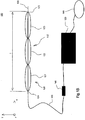
- FIG. 1A and 1B A first preferred embodiment of a bone expansion medical device 100 according to the invention is shown schematically.
- the medical device 100 comprises, in addition to the expansion device 110 according to the invention, a line 140 and an actuator 150 in the form of a pump, the expansion device 110 being connected to the pump 150 via the line 140.
- Expansion device 110 shown has an envelope element 120 designed as an envelope balloon, in which a plurality of expansion devices 121, 122, 123 are provided in the form of chambers.
- the sheath element 120 is made of a flexible material, such as a polyolefin-based elastomer, a silicone suitable for medical applications, or generally of an elastic polymer.
- the sheath element 120 may expand along with the chambers 121, 122, 123 in the expansion described below.
- X direction shown corresponds to the longitudinal direction of the expansion device 110 according to the invention.
- the expansion device 110 extends between a proximal 124 and a distal end 125 in this longitudinal direction.
- the sheath element 120 also extends along this in FIG Fig. 1A shown X-direction and includes the chambers 121, 122, 123 completely.
- a metal core 130 which preferably has a diameter of 1 mm.
- the metal core 130 is provided for increasing the stability of the expansion device 110 and facilitates the insertion of the expansion device 110 into a long bone.
- the metal core 130 is also formed such that it has a good X-ray contrast. As a result, the position of the expansion device 110 within the tubular bone can be checked well.
- the entire length / in Fig. 1A shown expansion device 110 is preferably between 8 and 25 cm. Your max. Diameter d is 0.3 cm in the contracted or contracted state.
- three chambers 121, 122, 123 are provided, each of which can be independently and individually filled with a particular medium, such as a liquid, gel or gas.
- the chambers 121, 122 and 123 are formed in this first embodiment by identical balloons, which in the in Fig. 1A shown longitudinal direction are arranged uniformly and directly successive.
- the wrapping element 120 encloses the chambers 121, 122 123 or balloons completely and sealed. This will bring the chambers 121, 122, 123 with no body elements, such as bone, bone marrow or body fluids in direct contact. This has the advantage that the chambers 121, 122, 123 can be dimensioned and formed materially only with regard to the expected maximum pressures or forces.
- the chambers / balloons 121, 122, 123 are configured to withstand a pressure of 25 bar.
- each of the pressure hoses 142, 143, 144 opens into one of the three chambers / balloons 121, 122, 123, respectively.
- the medium can be passed into the corresponding chamber, whereby the expansion device 110 in the in Fig. 1A shown longitudinal direction (X direction) sections radially (YZ plane) can be extended.
- the chambers / balloons 121, 122, 123 can be independently filled with the medium, and therefore the expansion device 110 can be expanded in a certain way.
- the chambers / balloons 121, 122, 123 in this first preferred embodiment are respectively connected to the metal core 130 indirectly or directly (fixedly), so that the chambers / balloons 121, 122, 123 are mainly in the radial direction (YZ) when the medium is introduced. Plane).
- connection element 141 connection / disconnection element
- connection element 141 From the connection element 141, the line 140 continues to the pump 150, which is located outside the body of the patient when the medical device is used as intended.
- This part of the line 140 i. from the connector 141 to the pump 150 is preferably coated with an antibiotic coating and / or a silver coating to prevent bacterial colonization of the conduit 140.
- the medium pumped by the pump 150 into the chambers / balloons 121, 122, 123 is contained in a reservoir 160.
- the reservoir 160 may be part of the pump 150 or, as in FIG Fig. 1A shown to be a separate reservoir.
- the medical device 100 shown may be configured such that the pump 150 and the reservoir 160 may be implanted into the body of the patient together with the expansion device 110.
- the expansion device 110, the conduit 140, the pump 150 and the reservoir 160 are completely received in the body of the patient, so no leads or elements must be led out of the body of the patient and the body of the patient after implantation completely again can be closed.
- This has the advantage that infections can be better prevented because bacteria and / or viruses can not get into the body of the patient through an entry point of the conduit.
- the reservoir 160 is preferably formed of a flexible, resilient material and may expand to accommodate various amounts of the medium.
- the volume of the reservoir 160 may vary depending on the amount of media to be received therein. It is not mandatory that the reservoir 160 be implanted already filled.
- a port vascular access system (not shown) that may be placed in the patient's tissue so that it can be pierced with a needle and the medium directed into the reservoir 160.
- This embodiment of the reservoir 160 is also advantageous in that it can be easily refilled.
- Fig. 2A is the in Fig. 1A shown expansion device 110 shown schematically in cross section.
- Fig. 2A apparent chamber corresponds to the one in Fig. 1A shown chamber 121 into which one of the pressure hoses 142, 143, 144 opens to the introduction of the medium and through which the remaining pressure hoses to the corresponding chambers.
- At least one elevation 126-four elevations in this preferred embodiment- is preferably provided, which is provided so that the expansion device 110 retains its position in the inserted state.
- the protrusions 126 provide for secure positioning of the expansion device 110 within the medullary cavity.
- the pressure hoses 142, 143, 144 may be received therein and extend in the bump (s) to the respective chambers / balloons 121, 122, 123.
- This formation of the elevation (s) 126 or this laying of the pressure hoses 142, 143, 144 has the advantage, for example, that the chambers 121, 122, 123 are better can be attached to the metal core 130, since at the junction between the chamber / balloon 121, 122, 123 and metal core 130 none of the pressure hoses 142, 143, 144 must be passed.
- a liquid such as a sodium chloride solution, water or a gel is used as the medium to be introduced.
- the pump 150 is preferably controlled by a controller (not shown).
- the controller may be included in the pump 150 or may be a separate unit from the pump 150.
- the control device can control the pump 150 in such a way that it pumps the medium step by step into the chambers and thus expands the expansion device step by step. In doing so, the pump can deliver the medium in uniform increments, i. always the same amount of liquid, or in uneven steps, i. different amounts of liquid, in the chambers / balloons 121, 122, 123 conduct.
- the control device may be programmed such that it automatically pumps a defined amount of the medium from the reservoir 160 into the expansion device 110 at certain time intervals.
- the controller may also drive the pump 150 such that the pump continuously expands the expansion device 100 or chambers / balloons 121, 122, 123 from an initial state.
- the controller determines the current volume of the expansion device based on the amount of liquid already introduced into the chambers 121, 122, 123 110 and the chambers / balloons 121, 122, 123 and the liquid to be introduced into the chambers / balloons 121, 122, 123, which is necessary for a desired expansion of the expansion device 110.
- the control device then controls the pump 150 in such a way that it pumps the amount of liquid to be introduced into the chambers / balloons 121, 122, 123.
- control device is preferably programmed such that it supplies the expansion device 110 with such an amount of liquid that it expands stepwise or continuously according to the principle of callus distraction.
- the controller is preferably configured to either be included in the pump 150 or to wirelessly drive the pump 150.
- the wireless control device comprises a cuff which is arranged on a specific body part of the patient and via which the control device can transfer control signals to the implanted pump 150, for example by applying a magnetic, electric or electromagnetic field.
- the control device can also be designed as a controller, wherein a metrologically detected variable, such as the pressure prevailing in the chambers or their volume, is fed back to the control device for control.
- a metrologically detected variable such as the pressure prevailing in the chambers or their volume
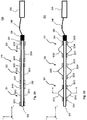
- a variant of the medical device 100 according to the invention is shown according to the first preferred embodiment of the invention, wherein this of the in Fig. 1A shown only differs in that the expansion device 110 has no envelope member 127.
- the chambers / balloons 121, 122, 123 come into direct contact with the bone to be expanded, which is why in this variant, the chambers or the balloons 121, 122, 123 are designed materially such that they are suitable for the direct Contact with the bone or bone marrow are suitable.
- Fig. 2B schematically shows a cross section of in Fig. 1B shown expansion device 100.
- the in Fig. 2B shown cross-section corresponds to a cross section of the first chamber 121. Since this variant of the expansion device 110 according to the invention has no enveloping element, the elevations 126 directly on the chambers / balloons 121, 122, 123 (in Fig. 2B formed on the chamber 121).
- Fig. 1C shows a second preferred embodiment of the medical device according to the invention.
- the medical device 200 shown in this figure differs from those described above in that the expansion device 210 is configured differently.
- the expansion device 210 is formed by a tube 220, which in the in Fig. 1C divided longitudinal direction shown (X-direction) is.
- X-direction For the segmentation of the tube this can be filled, for example, with a silicone at appropriate points and sealed so that the chambers 221, 222, 223 are formed.
- Fig. 2C shows a cross section of in Fig. 1C
- the pressure hoses 142-144 through the chambers 221, 222, 223, each of the pressure hoses in each case into an associated chamber 212, 222, 223 opens.
- the tube 220 is formed so that it does not have a constant inner diameter, which is why the wall thickness of the tube 220 changes. This is advantageous in that the tube 220 does not expand uniformly in all directions during expansion, which is why the expansion device 210 does not readily rotate within the bone marrow and remains stationary.
- FIG. 1D A variant of the medical device 200 according to the second preferred embodiment according to the invention is shown, wherein these differ from the one described with reference to FIG Fig. 1C described differs in that the tube 227 is divided into individual each associated with a chamber sections / hose pieces. Each piece of tubing is assigned one of the chambers 221, 222, 223.
- the medical device 300 includes a bone expansion expansion device 310.
- FIGS. 3A and 3B show the expansion device 310 on the one hand in a contracted or contracted state ( Fig. 3A ) and on the other hand in its expanded state ( Fig. 3B ).
- FIGS. 3A and 3B X direction shown corresponds to the longitudinal direction of the expansion device 310 according to the invention, in which the expansion device 310 extends from a proximal end 324 to a distal end 325.
- the expansion device 310 comprises three expansion devices 321, 322, 323, which in this embodiment are designed as mechanical spring elements.
- the spring elements 321, 322, 323 are constructed identically.
- the spring elements 321, 322, 323 each have a first leaf spring 3212, 3222, 3232 and a second leaf spring 3214, 3224, 3234, each on one side on a first sleeve 3211, 3221, 3231 and on the other hand on a second sleeve 3213, 3223, 3233 are attached.
- the spring elements 321, 322, 323 cooperate with a threaded spindle 330 in such a way that the spring elements 321, 322, 323 or their leaf springs can be expanded.
- the first and second sleeves are arranged on the threaded spindle 330 and the threaded spindle 330 is passed through the first and second sleeves.
- the first sleeves 3211, 3221, 3231 and the threaded spindle 330 engage in one another via a thread such that by rotating the threaded spindle 330, the first sleeves 3211, 3221, 3231 on the threaded spindle 330 can be translationally displaced in the X direction.
- the state of the expansion device 310 in which the first sleeves 3211, 3221, 3231 are offset is in FIG Fig. 3B shown.
- the second sleeves 3213, 3223, 3233 are rotatably mounted on the threaded spindle 330, but are not offset by rotation of the threaded spindle 330, but remain stationary upon rotation of the threaded spindle 330 with respect to the longitudinal direction of the expansion device 310 (X direction).
- expansion device 310 expands, or spring elements 321, 322, 323 expand upon rotation of threaded spindle 330, and when expander 310 is disposed within a tubular bone to be expanded, force is applied to the long bone via each spring element 321, 322, 323 is exercised for callus distraction.
- the threaded spindle 330 is preferably designed such that it can be bent to a certain extent. This facilitates placement of the expander 330 within a long bone through an intramedullary approach.
- FIGS. 3A and 3B Coupling device 326 shown provided, in which the expansion device 310 can be coupled to an actuator 350 via a flexible torsion transmission element 340.
- the actuator is realized by an electric motor operated by a controller (not shown) so as to rotate the screw shaft 330 to expand the expansion device 310.
- the actuator i. the electric motor 350 may be configured to be implanted into the body of the patient along with the expander 310.
- the control device can control the electric motor in such a way that it rotates the threaded spindle 330 stepwise and thus expands the spring elements 321, 322, 323 in a stepwise manner.
- the electric motor 350 can rotate the threaded spindle 330 in uniform steps or in uneven steps.
- the controller may be programmed to automatically rotate the threaded spindle 330 at defined intervals by a defined amount.
- control device can also control the electric motor 350 such that the expansion device 310 or the spring elements 321, 322, 323 are continuously expanded from an initial state.
- control device controls the actuator or the electric motor so that it expands the expansion device 330 according to the principle of callus distraction.
- the force necessary for rotation of the threaded spindle 330 which provides a conclusion to the forces exerted by the spring elements 321, 322, 323 on the long bones, is determined and used for control (or returned to the control device).
- Fig. 4 shows a schematic sectional view of the expansion device 310 according to the invention along the in Fig. 3B shown section line 4-4.
- the forces F can be exerted on a tubular bone in which the expansion device 310 is arranged via the leaf springs 3212, 3214, which expand in the Y direction shown.
- hollow profiles are preferably used, in which the threaded spindle 330 can be introduced.
- the hollow profiles are slit (partially) at two opposite and longitudinal (X-direction) extending portions such that the longitudinal end portions of the hollow profiles form the first and second sleeves.
- the lying between the sleeves and extending in the longitudinal direction sections form the leaf springs.
- first and / or second sleeves stops may be preferably provided on the first and / or second sleeves stops, which come into abutment when the first sleeves 3211, 3221, 3231 are offset beyond a certain extent.
- the stops are preferred in the in Fig. 4 arranged YZ plane between the leaf springs arranged. In that regard, the attacks can also be cut out of the hollow profile in the manufacture of the spring elements.
- the spring elements 321, 322, 323 also have a plurality of leaf springs, for example three or four leaf springs.
- the third and fourth leaf springs 3215, 3216 are offset relative to the first and second leaf springs 3212, 3214 by 90 ° (about the axis of the threaded spindle 330).
- the third and fourth leaf springs 3215, 3216 are also secured to the first and second sleeves 3211, 3213.
- the lead screw 330 is rotated, the third and fourth leaf springs 3215, 3216 are bent outward as well as the first and second leaf springs 3212, 3214 and the corresponding spring element 321 is expanded.
- the spring elements 321, 322, 323 have been described above as identical. However, the invention is not limited thereto.
- the spring elements 321, 322, 323 may also be different.
- the spring constants of a spring element or different spring elements associated leaf springs may be different.
- the spring elements 321, 322, 323 may be configured such that the corresponding second sleeves 3213, 3223, 3233 also engage with the threaded spindle 330 via a thread.
- the threaded spindle 330 it is necessary for the threaded spindle 330 to have counter-rotating threads in the portion associated with one of the spring members such that depending on the direction of rotation of the threaded spindle 330, the respective first and second sleeves will either approach or reverse in the opposite direction become.
- the spring elements 321, 322, 323 to be expanded may be uniformly or differently dimensioned depending on the type of tubular bone to be expanded, so that the long bone in which the expansion device 310 is disposed in one certain way - preferably according to the principle of callus distraction - can be extended.
- FIGS. 6A and 6B show a fourth embodiment of the medical device according to the invention.
- the medical device 400 is different from that described with reference to FIGS. 3A and 3B explained by the fact that the expansion means of the expansion device 410, no spring elements, but as scissor elements 421, 422, 423 are formed.
- the expansion device 410 also has three expansion devices 421, 422, 423, wherein instead of the leaf springs, the corresponding sleeves 3211, 3213, 3221, 3223, 3231, 3233 are connected to each other via struts.
- the scissor elements 421, 422, 423 are constructed identically, which is why they are described only with reference to the first scissor element 421.
- the struts 4211, 4212, 4213, 4214 of the first scissor element 421 are mounted on the one hand rotatably mounted on the sleeves 3211, 3213 and on the other hand connected to a common joint 4215, 4216 rotatably connected to each other.
- the struts 4211, 4212, 4213, 4214 carry at their common connection points 4215, 4216 each have a force distribution element 424, 425 over which the scissor element 421 upon rotation of the threaded spindle 330 can exert the force for bone expansion or callus distraction on the bone, said Force distribution elements 424, 425 are configured so that they distribute the applied force in terms of area.
- the force distributing members 424, 425 are formed in this embodiment as power distribution struts each extending in the longitudinal direction (X direction) and supported / supported by the longitudinally successive scissors members 421, 422, 423.
- the force distribution struts 424, 425 are here respectively attached to the joints of the struts of the first to third scissor element, so that the force distribution struts 424, 425 are uniformly raised upon rotation of the threaded spindle 330 and extension of the scissor elements 421, 422, 423.
- the scissor elements 421, 422, 423 are configured to be like those in FIG Fig. 4 expand leaf springs shown in the Y direction.
- the scissor elements 421, 422, 423 may also have additional struts which, like those in FIG Fig. 5 shown leaf springs are offset by 90 °. As a result, the force exerted on the bone for bone expansion can be better distributed.
- the additional struts may also carry at their junctions a force distribution element or a force distribution strut.
- the force distribution struts 424, 425 preferably have a circular cross-section (YZ plane) such that the force distribution struts 424, 425 form a closed-shell enclosure in the fully contracted state of the expansion device 410 ,
- devices for faster bone expansion / callus distraction may be provided.
Landscapes
- Health & Medical Sciences (AREA)
- Orthopedic Medicine & Surgery (AREA)
- Life Sciences & Earth Sciences (AREA)
- Surgery (AREA)
- Medical Informatics (AREA)
- Engineering & Computer Science (AREA)
- Biomedical Technology (AREA)
- Heart & Thoracic Surgery (AREA)
- Nuclear Medicine, Radiotherapy & Molecular Imaging (AREA)
- Molecular Biology (AREA)
- Animal Behavior & Ethology (AREA)
- General Health & Medical Sciences (AREA)
- Public Health (AREA)
- Veterinary Medicine (AREA)
- Neurology (AREA)
- Prostheses (AREA)
- Surgical Instruments (AREA)
Claims (14)
- Dispositif médical, comprenant
un dispositif d'expansion pour l'expansion osseuse, présentant une extrémité proximale et une extrémité distale entre lesquelles s'étend le dispositif d'expansion dans une direction longitudinale, et des dispositifs d'allongement disposés successivement dans la direction longitudinale, où
les dispositifs d'allongement peuvent être étirés pour exercer une force sur un os ;
un actionneur prévu pour étirer les dispositifs d'allongement du dispositif d'expansion ;
caractérisé par
un dispositif de commande pouvant commander l'actionneur de sorte que les dispositifs d'allongement s'étirent conformément au principe de distraction osseuse par callotase. - Dispositif médical selon la revendication 1, où
le dispositif de commande peut commander l'actionneur de sorte que les dispositifs d'allongement s'étirent de manière régulière ou irrégulière. - Dispositif médical selon la revendication 1 ou 2, où
les dispositifs d'allongement sont des chambres pouvant être remplies d'un milieu et où l'actionneur est une pompe prévue pour pouvoir refouler le milieu dans les chambres. - Dispositif médical selon la revendication 3, où
la pompe est prévue pour refouler un liquide dans les chambres ; et où
le dispositif de commande peut commander la pompe de sorte que les chambres s'étirent conformément au principe de distraction osseuse par callotase. - Dispositif médical selon la revendication 4, où le liquide est un liquide de contraste radio-opaque ou un liquide inerte.
- Dispositif médical selon la revendication 4 ou 5, comprenant en outre un générateur d'ultrasons, prévu de manière à permettre la pénétration d'ultrasons dans le dispositif d'expansion au moyen du liquide.
- Dispositif médical selon l'une des revendications 1 à 6, où le dispositif de commande est prévu pour étirer les dispositifs d'allongement de manière continue ou par pas.
- Dispositif médical selon l'une des revendications 1 à 7, où l'actionneur est réalisé de manière à pouvoir être disposé et mis en service dans le tissu corporel pendant la distraction osseuse.
- Dispositif médical selon l'une des revendications 3 à 6, où les chambres sont formées par des ballonnets.
- Dispositif médical selon l'une des revendications 3 à 6, où les chambres sont formées par segmentation d'un tuyau qui s'étend dans la direction longitudinale.
- Dispositif médical selon l'une des revendications 3 à 6, où les chambres sont formées chacune par un tuyau et où les tuyaux sont disposés successivement dans la direction longitudinale.
- Dispositif médical selon l'une des revendications 3 à 6 ou 9 à 11, où les chambres peuvent être remplies chacune de milieu au moyen d'un tuyau de refoulement.
- Dispositif médical selon la revendication 12, où le tuyau de refoulement est revêtu d'une couche qui empêche une colonisation bactérienne du tuyau de refoulement.
- Dispositif médical selon l'une des revendications 1 à 13, où une âme métallique s'étend au travers du dispositif d'expansion dans la direction longitudinale pour accroître la stabilité du dispositif d'expansion.
Applications Claiming Priority (3)
| Application Number | Priority Date | Filing Date | Title |
|---|---|---|---|
| DE102011110995 | 2011-08-18 | ||
| DE102012207968 | 2012-05-11 | ||
| PCT/EP2012/064838 WO2013023898A1 (fr) | 2011-08-18 | 2012-07-27 | Dispositif d'expansion pour l'expansion osseuse et dispositif médical d'expansion osseuse |
Publications (2)
| Publication Number | Publication Date |
|---|---|
| EP2744433A1 EP2744433A1 (fr) | 2014-06-25 |
| EP2744433B1 true EP2744433B1 (fr) | 2016-03-30 |
Family
ID=46651478
Family Applications (1)
| Application Number | Title | Priority Date | Filing Date |
|---|---|---|---|
| EP12746306.5A Active EP2744433B1 (fr) | 2011-08-18 | 2012-07-27 | Dispositif médical d'expansion osseuse |
Country Status (5)
| Country | Link |
|---|---|
| US (1) | US9839461B2 (fr) |
| EP (1) | EP2744433B1 (fr) |
| JP (1) | JP5927297B2 (fr) |
| CA (1) | CA2845654C (fr) |
| WO (1) | WO2013023898A1 (fr) |
Families Citing this family (12)
| Publication number | Priority date | Publication date | Assignee | Title |
|---|---|---|---|---|
| CA2845654C (fr) * | 2011-08-18 | 2016-09-13 | Matthias Militz | Dispositif d'expansion pour l'expansion osseuse et dispositif medical d'expansion osseuse |
| US9358120B2 (en) | 2013-03-14 | 2016-06-07 | DePuy Synthes Products, Inc. | Expandable coil spinal implant |
| US9572676B2 (en) * | 2013-03-14 | 2017-02-21 | DePuy Synthes Products, Inc. | Adjustable multi-volume balloon for spinal interventions |
| US9585761B2 (en) | 2013-03-14 | 2017-03-07 | DePuy Synthes Products, Inc. | Angulated rings and bonded foils for use with balloons for fusion and dynamic stabilization |
| TWI528938B (zh) * | 2014-03-21 | 2016-04-11 | Spirit Spine Holdings Corp Inc | Bone fixation device |
| CN105011993B (zh) * | 2014-04-17 | 2018-06-01 | 思必瑞特脊椎股份有限公司 | 骨固定装置 |
| US9974581B2 (en) | 2015-11-20 | 2018-05-22 | Globus Medical, Inc. | Expandable intramedullary systems and methods of using the same |
| US9827025B2 (en) | 2015-11-20 | 2017-11-28 | Globus Medical, Inc. | Expandable intramedullary systems and methods of using the same |
| US10092333B2 (en) | 2015-11-20 | 2018-10-09 | Globus Medical, Inc. | Expandable intramedullary systems and methods of using the same |
| US20230404639A1 (en) * | 2020-10-31 | 2023-12-21 | Ot Medizintechnik Gmbh | Medical expansion system for expanding a long bone, and kit |
| DE102021112429B4 (de) | 2021-05-12 | 2025-02-27 | Roman Stauch | Marknagel zur transversalen Distraktion |
| US12453583B2 (en) | 2023-12-04 | 2025-10-28 | BioDynamik, Inc. | Systems and methods for transport and tissue distraction |
Family Cites Families (55)
| Publication number | Priority date | Publication date | Assignee | Title |
|---|---|---|---|---|
| FR2653006A1 (fr) | 1989-10-12 | 1991-04-19 | Dorange Arnaud | Clou centromedullaire a fixateurs internes multiples. |
| US5423850A (en) * | 1993-10-01 | 1995-06-13 | Berger; J. Lee | Balloon compressor for internal fixation of bone fractures |
| US20030032963A1 (en) * | 2001-10-24 | 2003-02-13 | Kyphon Inc. | Devices and methods using an expandable body with internal restraint for compressing cancellous bone |
| US20060271061A1 (en) * | 2001-07-25 | 2006-11-30 | Disc-O-Tech, Ltd. | Deformable tools and implants |
| US5919163A (en) * | 1997-07-14 | 1999-07-06 | Delcath Systems, Inc. | Catheter with slidable balloon |
| DE69837611T2 (de) * | 1997-10-01 | 2007-12-27 | Boston Scientific Ltd., St. Michael | Dilatationssysteme |
| US6659957B1 (en) * | 1998-03-05 | 2003-12-09 | Gil M. Vardi | Optical-acoustic imaging device |
| US6264659B1 (en) * | 1999-02-22 | 2001-07-24 | Anthony C. Ross | Method of treating an intervertebral disk |
| CA2411944C (fr) * | 2000-06-09 | 2010-12-14 | Baylor College Of Medicine | Combinaison d'agents antimicrobiens et d'une interference bacterienne servant a enduire des dispositifs medicaux |
| US6685672B1 (en) * | 2000-07-13 | 2004-02-03 | Edwards Lifesciences Corporation | Multi-balloon drug delivery catheter for angiogenesis |
| US6632235B2 (en) * | 2001-04-19 | 2003-10-14 | Synthes (U.S.A.) | Inflatable device and method for reducing fractures in bone and in treating the spine |
| US20050209629A1 (en) * | 2001-04-19 | 2005-09-22 | Kerr Sean H | Resorbable containment device and process for making and using same |
| US6706069B2 (en) * | 2001-09-13 | 2004-03-16 | J. Lee Berger | Spinal grooved director with built in balloon |
| US9155544B2 (en) * | 2002-03-20 | 2015-10-13 | P Tech, Llc | Robotic systems and methods |
| US20040068226A1 (en) * | 2002-10-02 | 2004-04-08 | Brannon James Kevin | Osteodwelling catheter |
| EP1786343B1 (fr) * | 2004-07-30 | 2012-05-02 | Depuy Spine, Inc. | Appareil de traitement des os et d'autres tissus |
| US20060184192A1 (en) * | 2005-02-11 | 2006-08-17 | Markworth Aaron D | Systems and methods for providing cavities in interior body regions |
| KR100550585B1 (ko) * | 2005-08-29 | 2006-02-10 | (주)태연메디칼 | 일회용의 척추복원시술용 복원기 |
| EP3517137A1 (fr) | 2005-11-14 | 2019-07-31 | Biomet 3I, LLC | Dépôt de nanoparticules discrètes sur une surface d'implant |
| US20070123877A1 (en) * | 2005-11-15 | 2007-05-31 | Aoi Medical, Inc. | Inflatable Device for Restoring Anatomy of Fractured Bone |
| US8202265B2 (en) * | 2006-04-20 | 2012-06-19 | Boston Scientific Scimed, Inc. | Multiple lumen assembly for use in endoscopes or other medical devices |
| US20080097374A1 (en) * | 2006-08-07 | 2008-04-24 | Korleski Joseph E | Inflatable shaped balloons |
| US20090012564A1 (en) * | 2007-03-07 | 2009-01-08 | Spineworks Medical, Inc. | Transdiscal interbody fusion device and method |
| US20090005821A1 (en) * | 2007-06-29 | 2009-01-01 | Spineworks Medical, Inc. | Methods and devices for stabilizing bone compatible for use with bone screws |
| DE102006044740A1 (de) * | 2006-09-20 | 2008-04-03 | Tracoe Medical Gmbh | Manschette einer Beatmungsvorrichtung |
| DE602008006537D1 (de) * | 2007-03-02 | 2011-06-09 | Spinealign Medical Inc | Fraktur-fixationssystem |
| GB0707394D0 (en) * | 2007-04-17 | 2007-05-23 | Smith & Nephew | Shape memory spine jack |
| US20110092859A1 (en) * | 2007-06-25 | 2011-04-21 | Neubardt Seth L | System for determining and placing spinal implants or prostheses |
| CN103271761B (zh) * | 2008-01-14 | 2015-10-28 | 康文图斯整形外科公司 | 用于骨折修补的装置和方法 |
| US9161798B2 (en) * | 2008-02-01 | 2015-10-20 | Dfine, Inc. | Bone treatment systems and methods |
| EP2810664B1 (fr) * | 2008-02-28 | 2019-05-29 | Dfine, Inc. | Composition de ciment osseux |
| US20090299327A1 (en) * | 2008-06-02 | 2009-12-03 | Lorna Vista Medical, Inc. | Inflatable medical devices |
| GB0813659D0 (en) * | 2008-07-25 | 2008-09-03 | Smith & Nephew | Fracture putty |
| US20110307072A1 (en) * | 2009-02-26 | 2011-12-15 | Deputy International Limited | Support structure implant for a bone cavity |
| US8617053B2 (en) * | 2009-04-24 | 2013-12-31 | Warsaw Othropedic, Inc. | Remote position control for surgical apparatus |
| WO2010135602A1 (fr) * | 2009-05-20 | 2010-11-25 | Osseon Therapeutics, Inc. | Cathéter d'ablation orientable et incurvable pour vertébroplastie |
| EP2473116B1 (fr) * | 2009-09-04 | 2019-12-04 | NuVasive Specialized Orthopedics, Inc. | Dispositif de croissance osseuse |
| US8545499B2 (en) * | 2009-09-28 | 2013-10-01 | Zimmer, Inc. | Expandable intramedullary rod |
| EP2351529B1 (fr) * | 2010-01-27 | 2019-06-05 | Aeeg Ab | Dispositif de support de plaie postopératoire |
| WO2011103370A1 (fr) * | 2010-02-17 | 2011-08-25 | Reprise Technologies, Llc | Système et procédé d'arthroscopie guidée par imagerie |
| US9220554B2 (en) * | 2010-02-18 | 2015-12-29 | Globus Medical, Inc. | Methods and apparatus for treating vertebral fractures |
| US8147526B2 (en) * | 2010-02-26 | 2012-04-03 | Kyphon Sarl | Interspinous process spacer diagnostic parallel balloon catheter and methods of use |
| US8684965B2 (en) * | 2010-06-21 | 2014-04-01 | Illuminoss Medical, Inc. | Photodynamic bone stabilization and drug delivery systems |
| AU2011282746A1 (en) * | 2010-07-27 | 2013-02-21 | Richard S. Ginn | System for sacro-iliac stabilization |
| WO2012088432A1 (fr) * | 2010-12-22 | 2012-06-28 | Illuminoss Medical, Inc. | Systèmes et méthodes de traitement d'affections et de maladies touchant la colonne vertébrale |
| US20120259355A1 (en) * | 2011-04-08 | 2012-10-11 | Kyphon Sarl | Retractable inflatable bone tamp |
| US8728081B2 (en) * | 2011-04-29 | 2014-05-20 | Warsaw Orthopedic, Inc. | Bone tamp and methods of use |
| US8454615B2 (en) * | 2011-07-05 | 2013-06-04 | Kyphon Sarl | Combination directional and non-directional bone tamp |
| CA2845654C (fr) * | 2011-08-18 | 2016-09-13 | Matthias Militz | Dispositif d'expansion pour l'expansion osseuse et dispositif medical d'expansion osseuse |
| KR101164852B1 (ko) * | 2011-12-05 | 2012-07-11 | 최길운 | 벌룬 카테터 |
| US20130238038A1 (en) * | 2012-03-07 | 2013-09-12 | Kyphon Sarl | Angled inflatable composite balloon and method |
| US9351779B2 (en) * | 2013-01-25 | 2016-05-31 | Kyphon SÀRL | Expandable device and methods of use |
| US9572676B2 (en) * | 2013-03-14 | 2017-02-21 | DePuy Synthes Products, Inc. | Adjustable multi-volume balloon for spinal interventions |
| US9585761B2 (en) * | 2013-03-14 | 2017-03-07 | DePuy Synthes Products, Inc. | Angulated rings and bonded foils for use with balloons for fusion and dynamic stabilization |
| US20150112351A1 (en) * | 2013-10-22 | 2015-04-23 | Spirit Spine Holdings Corporation, Inc. | Device for bone fixation |
-
2012
- 2012-07-27 CA CA2845654A patent/CA2845654C/fr active Active
- 2012-07-27 WO PCT/EP2012/064838 patent/WO2013023898A1/fr not_active Ceased
- 2012-07-27 EP EP12746306.5A patent/EP2744433B1/fr active Active
- 2012-07-27 US US14/239,399 patent/US9839461B2/en active Active
- 2012-07-27 JP JP2014525385A patent/JP5927297B2/ja active Active
Also Published As
| Publication number | Publication date |
|---|---|
| US9839461B2 (en) | 2017-12-12 |
| JP2014528765A (ja) | 2014-10-30 |
| US20140222094A1 (en) | 2014-08-07 |
| JP5927297B2 (ja) | 2016-06-01 |
| WO2013023898A1 (fr) | 2013-02-21 |
| CA2845654C (fr) | 2016-09-13 |
| CA2845654A1 (fr) | 2013-02-21 |
| EP2744433A1 (fr) | 2014-06-25 |
Similar Documents
| Publication | Publication Date | Title |
|---|---|---|
| WO2013023898A1 (fr) | Dispositif d'expansion pour l'expansion osseuse et dispositif médical d'expansion osseuse | |
| EP3135206B1 (fr) | Dispositif de traitement des varices | |
| DE60304127T2 (de) | Wirbelkörper-Distraktor | |
| EP1014867B1 (fr) | Dispositif pour l'implantation de materiaux filiformes | |
| DE102007003645A1 (de) | Instrument zur Behandlung geschädigter Wirbelkörper | |
| EP1509175A1 (fr) | Implant de type ballon gonflable | |
| DE19741757A1 (de) | Hydraulisches, implantierbares Knochenexpansionsgerät | |
| CH707319A1 (de) | Stentapplikator. | |
| DE4012366A1 (de) | Verlaengerung von linearem und rohrfoermigem gewebe | |
| DE102005021470A1 (de) | Einführhilfe für die perkutane Tracheostomie | |
| EP3025760B1 (fr) | Conception d'un éloignement simplifié d'un applicateur de ballon | |
| DE4418263A1 (de) | Vorrichtung zum Austauschen einer Kanüle | |
| EP1009306A1 (fr) | Systeme d'electrodes pour le traitement electrothermique du corps humain ou du corps animal | |
| EP1749491A2 (fr) | Dispositif de traitement de corps vertébraux | |
| DE112018006160T5 (de) | Vorrichtung für direktionale kyphoplastie und verfahren zur verwendung einer solchen vorrichtung | |
| EP4045125A1 (fr) | Élément de guidage conçu pour un système d'élargissement vasculaire commandable, et système d'élargissement vasculaire commandable | |
| EP2422726B1 (fr) | Dispositifs de cyphoplastie vertébrale à ballonnet | |
| EP2455018B1 (fr) | Gaine de trocart pour l'introduction dans une incision de peau | |
| DE102009060279B4 (de) | Vorrichtung zur Zufuhr eines medizinischen Implantats und Anordnung mit einer derartigen Vorrichtung | |
| EP3228271B1 (fr) | Cathéter à double ballonnet | |
| EP3117786A1 (fr) | Instrument de retrait de tissus corporels d'un canal de fistule | |
| EP2589349B1 (fr) | Dispositif médical pour l'introduction d'instruments endoscopiques dans une ouverture corporelle | |
| DE102004033693B4 (de) | Vorrichtung zur medizinischen Verödung von Geweben | |
| DE19959975A1 (de) | Kanüle und Instrumentenset | |
| EP2921143B1 (fr) | Instrument de tampon et système comprenant celui-ci destiné à traiter une structure osseuse ou de cartilage |
Legal Events
| Date | Code | Title | Description |
|---|---|---|---|
| PUAI | Public reference made under article 153(3) epc to a published international application that has entered the european phase |
Free format text: ORIGINAL CODE: 0009012 |
|
| 17P | Request for examination filed |
Effective date: 20140318 |
|
| AK | Designated contracting states |
Kind code of ref document: A1 Designated state(s): AL AT BE BG CH CY CZ DE DK EE ES FI FR GB GR HR HU IE IS IT LI LT LU LV MC MK MT NL NO PL PT RO RS SE SI SK SM TR |
|
| DAX | Request for extension of the european patent (deleted) | ||
| GRAP | Despatch of communication of intention to grant a patent |
Free format text: ORIGINAL CODE: EPIDOSNIGR1 |
|
| INTG | Intention to grant announced |
Effective date: 20150310 |
|
| GRAP | Despatch of communication of intention to grant a patent |
Free format text: ORIGINAL CODE: EPIDOSNIGR1 |
|
| INTG | Intention to grant announced |
Effective date: 20150915 |
|
| GRAS | Grant fee paid |
Free format text: ORIGINAL CODE: EPIDOSNIGR3 |
|
| GRAA | (expected) grant |
Free format text: ORIGINAL CODE: 0009210 |
|
| AK | Designated contracting states |
Kind code of ref document: B1 Designated state(s): AL AT BE BG CH CY CZ DE DK EE ES FI FR GB GR HR HU IE IS IT LI LT LU LV MC MK MT NL NO PL PT RO RS SE SI SK SM TR |
|
| REG | Reference to a national code |
Ref country code: GB Ref legal event code: FG4D Free format text: NOT ENGLISH |
|
| REG | Reference to a national code |
Ref country code: CH Ref legal event code: EP |
|
| REG | Reference to a national code |
Ref country code: AT Ref legal event code: REF Ref document number: 784454 Country of ref document: AT Kind code of ref document: T Effective date: 20160415 |
|
| REG | Reference to a national code |
Ref country code: IE Ref legal event code: FG4D Free format text: LANGUAGE OF EP DOCUMENT: GERMAN |
|
| REG | Reference to a national code |
Ref country code: DE Ref legal event code: R096 Ref document number: 502012006519 Country of ref document: DE |
|
| REG | Reference to a national code |
Ref country code: FR Ref legal event code: PLFP Year of fee payment: 5 |
|
| REG | Reference to a national code |
Ref country code: LT Ref legal event code: MG4D |
|
| PG25 | Lapsed in a contracting state [announced via postgrant information from national office to epo] |
Ref country code: HR Free format text: LAPSE BECAUSE OF FAILURE TO SUBMIT A TRANSLATION OF THE DESCRIPTION OR TO PAY THE FEE WITHIN THE PRESCRIBED TIME-LIMIT Effective date: 20160330 Ref country code: GR Free format text: LAPSE BECAUSE OF FAILURE TO SUBMIT A TRANSLATION OF THE DESCRIPTION OR TO PAY THE FEE WITHIN THE PRESCRIBED TIME-LIMIT Effective date: 20160701 Ref country code: FI Free format text: LAPSE BECAUSE OF FAILURE TO SUBMIT A TRANSLATION OF THE DESCRIPTION OR TO PAY THE FEE WITHIN THE PRESCRIBED TIME-LIMIT Effective date: 20160330 Ref country code: NO Free format text: LAPSE BECAUSE OF FAILURE TO SUBMIT A TRANSLATION OF THE DESCRIPTION OR TO PAY THE FEE WITHIN THE PRESCRIBED TIME-LIMIT Effective date: 20160630 |
|
| REG | Reference to a national code |
Ref country code: NL Ref legal event code: MP Effective date: 20160330 |
|
| PG25 | Lapsed in a contracting state [announced via postgrant information from national office to epo] |
Ref country code: LV Free format text: LAPSE BECAUSE OF FAILURE TO SUBMIT A TRANSLATION OF THE DESCRIPTION OR TO PAY THE FEE WITHIN THE PRESCRIBED TIME-LIMIT Effective date: 20160330 Ref country code: LT Free format text: LAPSE BECAUSE OF FAILURE TO SUBMIT A TRANSLATION OF THE DESCRIPTION OR TO PAY THE FEE WITHIN THE PRESCRIBED TIME-LIMIT Effective date: 20160330 Ref country code: SE Free format text: LAPSE BECAUSE OF FAILURE TO SUBMIT A TRANSLATION OF THE DESCRIPTION OR TO PAY THE FEE WITHIN THE PRESCRIBED TIME-LIMIT Effective date: 20160330 Ref country code: RS Free format text: LAPSE BECAUSE OF FAILURE TO SUBMIT A TRANSLATION OF THE DESCRIPTION OR TO PAY THE FEE WITHIN THE PRESCRIBED TIME-LIMIT Effective date: 20160330 |
|
| PG25 | Lapsed in a contracting state [announced via postgrant information from national office to epo] |
Ref country code: NL Free format text: LAPSE BECAUSE OF FAILURE TO SUBMIT A TRANSLATION OF THE DESCRIPTION OR TO PAY THE FEE WITHIN THE PRESCRIBED TIME-LIMIT Effective date: 20160330 |
|
| PG25 | Lapsed in a contracting state [announced via postgrant information from national office to epo] |
Ref country code: PL Free format text: LAPSE BECAUSE OF FAILURE TO SUBMIT A TRANSLATION OF THE DESCRIPTION OR TO PAY THE FEE WITHIN THE PRESCRIBED TIME-LIMIT Effective date: 20160330 Ref country code: IS Free format text: LAPSE BECAUSE OF FAILURE TO SUBMIT A TRANSLATION OF THE DESCRIPTION OR TO PAY THE FEE WITHIN THE PRESCRIBED TIME-LIMIT Effective date: 20160730 Ref country code: EE Free format text: LAPSE BECAUSE OF FAILURE TO SUBMIT A TRANSLATION OF THE DESCRIPTION OR TO PAY THE FEE WITHIN THE PRESCRIBED TIME-LIMIT Effective date: 20160330 |
|
| PG25 | Lapsed in a contracting state [announced via postgrant information from national office to epo] |
Ref country code: ES Free format text: LAPSE BECAUSE OF FAILURE TO SUBMIT A TRANSLATION OF THE DESCRIPTION OR TO PAY THE FEE WITHIN THE PRESCRIBED TIME-LIMIT Effective date: 20160330 Ref country code: SM Free format text: LAPSE BECAUSE OF FAILURE TO SUBMIT A TRANSLATION OF THE DESCRIPTION OR TO PAY THE FEE WITHIN THE PRESCRIBED TIME-LIMIT Effective date: 20160330 Ref country code: PT Free format text: LAPSE BECAUSE OF FAILURE TO SUBMIT A TRANSLATION OF THE DESCRIPTION OR TO PAY THE FEE WITHIN THE PRESCRIBED TIME-LIMIT Effective date: 20160801 Ref country code: RO Free format text: LAPSE BECAUSE OF FAILURE TO SUBMIT A TRANSLATION OF THE DESCRIPTION OR TO PAY THE FEE WITHIN THE PRESCRIBED TIME-LIMIT Effective date: 20160330 Ref country code: CZ Free format text: LAPSE BECAUSE OF FAILURE TO SUBMIT A TRANSLATION OF THE DESCRIPTION OR TO PAY THE FEE WITHIN THE PRESCRIBED TIME-LIMIT Effective date: 20160330 Ref country code: SK Free format text: LAPSE BECAUSE OF FAILURE TO SUBMIT A TRANSLATION OF THE DESCRIPTION OR TO PAY THE FEE WITHIN THE PRESCRIBED TIME-LIMIT Effective date: 20160330 |
|
| PG25 | Lapsed in a contracting state [announced via postgrant information from national office to epo] |
Ref country code: IT Free format text: LAPSE BECAUSE OF FAILURE TO SUBMIT A TRANSLATION OF THE DESCRIPTION OR TO PAY THE FEE WITHIN THE PRESCRIBED TIME-LIMIT Effective date: 20160330 Ref country code: BE Free format text: LAPSE BECAUSE OF NON-PAYMENT OF DUE FEES Effective date: 20160731 |
|
| REG | Reference to a national code |
Ref country code: DE Ref legal event code: R097 Ref document number: 502012006519 Country of ref document: DE |
|
| PG25 | Lapsed in a contracting state [announced via postgrant information from national office to epo] |
Ref country code: DK Free format text: LAPSE BECAUSE OF FAILURE TO SUBMIT A TRANSLATION OF THE DESCRIPTION OR TO PAY THE FEE WITHIN THE PRESCRIBED TIME-LIMIT Effective date: 20160330 |
|
| PLBE | No opposition filed within time limit |
Free format text: ORIGINAL CODE: 0009261 |
|
| STAA | Information on the status of an ep patent application or granted ep patent |
Free format text: STATUS: NO OPPOSITION FILED WITHIN TIME LIMIT |
|
| REG | Reference to a national code |
Ref country code: CH Ref legal event code: PL |
|
| 26N | No opposition filed |
Effective date: 20170103 |
|
| PG25 | Lapsed in a contracting state [announced via postgrant information from national office to epo] |
Ref country code: MC Free format text: LAPSE BECAUSE OF FAILURE TO SUBMIT A TRANSLATION OF THE DESCRIPTION OR TO PAY THE FEE WITHIN THE PRESCRIBED TIME-LIMIT Effective date: 20160330 |
|
| PG25 | Lapsed in a contracting state [announced via postgrant information from national office to epo] |
Ref country code: CH Free format text: LAPSE BECAUSE OF NON-PAYMENT OF DUE FEES Effective date: 20160731 Ref country code: LI Free format text: LAPSE BECAUSE OF NON-PAYMENT OF DUE FEES Effective date: 20160731 |
|
| REG | Reference to a national code |
Ref country code: IE Ref legal event code: MM4A |
|
| PG25 | Lapsed in a contracting state [announced via postgrant information from national office to epo] |
Ref country code: SI Free format text: LAPSE BECAUSE OF FAILURE TO SUBMIT A TRANSLATION OF THE DESCRIPTION OR TO PAY THE FEE WITHIN THE PRESCRIBED TIME-LIMIT Effective date: 20160330 |
|
| REG | Reference to a national code |
Ref country code: FR Ref legal event code: PLFP Year of fee payment: 6 |
|
| PG25 | Lapsed in a contracting state [announced via postgrant information from national office to epo] |
Ref country code: IE Free format text: LAPSE BECAUSE OF NON-PAYMENT OF DUE FEES Effective date: 20160727 |
|
| PG25 | Lapsed in a contracting state [announced via postgrant information from national office to epo] |
Ref country code: LU Free format text: LAPSE BECAUSE OF NON-PAYMENT OF DUE FEES Effective date: 20160727 |
|
| PG25 | Lapsed in a contracting state [announced via postgrant information from national office to epo] |
Ref country code: HU Free format text: LAPSE BECAUSE OF FAILURE TO SUBMIT A TRANSLATION OF THE DESCRIPTION OR TO PAY THE FEE WITHIN THE PRESCRIBED TIME-LIMIT; INVALID AB INITIO Effective date: 20120727 Ref country code: CY Free format text: LAPSE BECAUSE OF FAILURE TO SUBMIT A TRANSLATION OF THE DESCRIPTION OR TO PAY THE FEE WITHIN THE PRESCRIBED TIME-LIMIT Effective date: 20160330 |
|
| PG25 | Lapsed in a contracting state [announced via postgrant information from national office to epo] |
Ref country code: MT Free format text: LAPSE BECAUSE OF FAILURE TO SUBMIT A TRANSLATION OF THE DESCRIPTION OR TO PAY THE FEE WITHIN THE PRESCRIBED TIME-LIMIT Effective date: 20160330 Ref country code: MK Free format text: LAPSE BECAUSE OF FAILURE TO SUBMIT A TRANSLATION OF THE DESCRIPTION OR TO PAY THE FEE WITHIN THE PRESCRIBED TIME-LIMIT Effective date: 20160330 |
|
| REG | Reference to a national code |
Ref country code: FR Ref legal event code: PLFP Year of fee payment: 7 |
|
| PG25 | Lapsed in a contracting state [announced via postgrant information from national office to epo] |
Ref country code: BG Free format text: LAPSE BECAUSE OF FAILURE TO SUBMIT A TRANSLATION OF THE DESCRIPTION OR TO PAY THE FEE WITHIN THE PRESCRIBED TIME-LIMIT Effective date: 20160330 |
|
| REG | Reference to a national code |
Ref country code: AT Ref legal event code: MM01 Ref document number: 784454 Country of ref document: AT Kind code of ref document: T Effective date: 20170727 |
|
| PG25 | Lapsed in a contracting state [announced via postgrant information from national office to epo] |
Ref country code: TR Free format text: LAPSE BECAUSE OF FAILURE TO SUBMIT A TRANSLATION OF THE DESCRIPTION OR TO PAY THE FEE WITHIN THE PRESCRIBED TIME-LIMIT Effective date: 20160330 Ref country code: AL Free format text: LAPSE BECAUSE OF FAILURE TO SUBMIT A TRANSLATION OF THE DESCRIPTION OR TO PAY THE FEE WITHIN THE PRESCRIBED TIME-LIMIT Effective date: 20160330 |
|
| PG25 | Lapsed in a contracting state [announced via postgrant information from national office to epo] |
Ref country code: AT Free format text: LAPSE BECAUSE OF NON-PAYMENT OF DUE FEES Effective date: 20170727 |
|
| REG | Reference to a national code |
Ref country code: DE Ref legal event code: R082 Ref document number: 502012006519 Country of ref document: DE Representative=s name: KILIAN KILIAN & PARTNER MBB PATENTANWAELTE, DE Ref country code: DE Ref legal event code: R081 Ref document number: 502012006519 Country of ref document: DE Owner name: SBONE GMBH, DE Free format text: FORMER OWNERS: MILITZ, MATTHIAS, DR., 82418 MURNAU, DE; OEHLBAUER, MARKUS, DR., 82418 MURNAU, DE |
|
| REG | Reference to a national code |
Ref country code: GB Ref legal event code: 732E Free format text: REGISTERED BETWEEN 20200514 AND 20200520 |
|
| PGFP | Annual fee paid to national office [announced via postgrant information from national office to epo] |
Ref country code: DE Payment date: 20250728 Year of fee payment: 14 |
|
| PGFP | Annual fee paid to national office [announced via postgrant information from national office to epo] |
Ref country code: GB Payment date: 20250728 Year of fee payment: 14 |
|
| PGFP | Annual fee paid to national office [announced via postgrant information from national office to epo] |
Ref country code: FR Payment date: 20250728 Year of fee payment: 14 |