EP2745754A1 - Dispositif destiné au recouvrement de récipients pour produits alimentaires avec différentes largeurs d'ouverture et de maintien au froid du contenu des récipients - Google Patents
Dispositif destiné au recouvrement de récipients pour produits alimentaires avec différentes largeurs d'ouverture et de maintien au froid du contenu des récipients Download PDFInfo
- Publication number
- EP2745754A1 EP2745754A1 EP13004083.5A EP13004083A EP2745754A1 EP 2745754 A1 EP2745754 A1 EP 2745754A1 EP 13004083 A EP13004083 A EP 13004083A EP 2745754 A1 EP2745754 A1 EP 2745754A1
- Authority
- EP
- European Patent Office
- Prior art keywords
- cover
- container
- lower cover
- upper cover
- region
- Prior art date
- Legal status (The legal status is an assumption and is not a legal conclusion. Google has not performed a legal analysis and makes no representation as to the accuracy of the status listed.)
- Withdrawn
Links
- 235000013305 food Nutrition 0.000 title claims abstract description 14
- 230000005489 elastic deformation Effects 0.000 claims abstract description 5
- 230000002787 reinforcement Effects 0.000 claims description 8
- 239000011521 glass Substances 0.000 claims description 5
- 229920001296 polysiloxane Polymers 0.000 claims description 5
- 239000013013 elastic material Substances 0.000 claims description 4
- 239000007787 solid Substances 0.000 claims description 3
- 230000000630 rising effect Effects 0.000 claims description 2
- 230000001154 acute effect Effects 0.000 claims 1
- 239000012530 fluid Substances 0.000 claims 1
- 230000005484 gravity Effects 0.000 claims 1
- 230000002093 peripheral effect Effects 0.000 claims 1
- 238000007493 shaping process Methods 0.000 claims 1
- 239000006228 supernatant Substances 0.000 claims 1
- 230000007704 transition Effects 0.000 claims 1
- 238000011038 discontinuous diafiltration by volume reduction Methods 0.000 abstract 1
- 239000007788 liquid Substances 0.000 description 10
- 238000010411 cooking Methods 0.000 description 7
- 230000005923 long-lasting effect Effects 0.000 description 4
- 238000004519 manufacturing process Methods 0.000 description 4
- 238000009835 boiling Methods 0.000 description 3
- 239000000463 material Substances 0.000 description 3
- 238000011109 contamination Methods 0.000 description 2
- 230000007547 defect Effects 0.000 description 2
- 230000000994 depressogenic effect Effects 0.000 description 2
- 230000003068 static effect Effects 0.000 description 2
- 239000013589 supplement Substances 0.000 description 2
- 230000005540 biological transmission Effects 0.000 description 1
- 230000015572 biosynthetic process Effects 0.000 description 1
- 239000011248 coating agent Substances 0.000 description 1
- 238000000576 coating method Methods 0.000 description 1
- 230000001447 compensatory effect Effects 0.000 description 1
- 239000000356 contaminant Substances 0.000 description 1
- 230000000881 depressing effect Effects 0.000 description 1
- 238000006073 displacement reaction Methods 0.000 description 1
- 239000010794 food waste Substances 0.000 description 1
- 230000014759 maintenance of location Effects 0.000 description 1
- 230000000873 masking effect Effects 0.000 description 1
- 239000000047 product Substances 0.000 description 1
- 238000011084 recovery Methods 0.000 description 1
- 230000003014 reinforcing effect Effects 0.000 description 1
- 230000000284 resting effect Effects 0.000 description 1
- 239000000565 sealant Substances 0.000 description 1
- 238000007789 sealing Methods 0.000 description 1
- XLYOFNOQVPJJNP-UHFFFAOYSA-N water Substances O XLYOFNOQVPJJNP-UHFFFAOYSA-N 0.000 description 1
Images

Classifications
-
- A—HUMAN NECESSITIES
- A47—FURNITURE; DOMESTIC ARTICLES OR APPLIANCES; COFFEE MILLS; SPICE MILLS; SUCTION CLEANERS IN GENERAL
- A47J—KITCHEN EQUIPMENT; COFFEE MILLS; SPICE MILLS; APPARATUS FOR MAKING BEVERAGES
- A47J36/00—Parts, details or accessories of cooking-vessels
- A47J36/06—Lids or covers for cooking-vessels
-
- A—HUMAN NECESSITIES
- A47—FURNITURE; DOMESTIC ARTICLES OR APPLIANCES; COFFEE MILLS; SPICE MILLS; SUCTION CLEANERS IN GENERAL
- A47J—KITCHEN EQUIPMENT; COFFEE MILLS; SPICE MILLS; APPARATUS FOR MAKING BEVERAGES
- A47J47/00—Kitchen containers, stands or the like, not provided for in other groups of this subclass; Cutting-boards, e.g. for bread
- A47J47/02—Closed containers for foodstuffs
- A47J47/08—Closed containers for foodstuffs for non-granulated foodstuffs
- A47J47/10—Closed containers for foodstuffs for non-granulated foodstuffs with arrangements for keeping fresh
Definitions
- the invention relates to a device for covering solid, open-topped food containers with different sized container openings, consisting of a cup-shaped lower cover and an upper cover, the lower cover with a lower, convex surface with projection on the upper edge of the respective container circumferentially attachable is, at least one passage opening in the region of the shell low point, which lies in the mounted state of the lower cover over the container opening, and at least in the region between the support line, which results when resting on the container edge of the largest container and one the passage opening or the passage openings outside enclosing boundary line made of elastic material, in particular made of silicone.
- the known device consists of a cup-shaped cover which is formed of an elastic material, in particular of silicone and with its lower, convex surface with projection on the upper edge of the respective container can be placed.
- the shell-shaped cover has at least one passage opening in the region of the shell low point or of the deepest shell surface area. The at least one passage opening is in the mounted state of the cup-shaped cover over the container opening.
- the device consists of a releasably connected to the lower cover closure part, which can be regarded as an upper cover and which is associated with this passage opening or these passage openings.
- the closure member closes the passage opening or passage openings. If the liquid boils so high that it touches the closure part, then the high-boiling liquid presses the closure part upwards, which, for example, is hinged to the bowl-shaped cover.
- the closure part must be designed very lightweight and thin-walled. The folding movement may counteract only a very small deformation or opening resistance.
- the closure part therefore has to react very sensitively and fold up even at the slightest opening forces, since otherwise the high boiling liquid does not flow through the passage opening (s) but through the gap would emerge between the upper cooking vessel edge and the loosely placed cup-shaped cover and thus no overcooking protection would be guaranteed.
- the high-boiling liquid passes through the passage opening or the passage openings up into the cup serving as a collecting cup-shaped cover, where the liquid is cold and can flow back through the passage opening back into the cooking vessel.
- the closure member provided in this known device can be regarded in its idle state as the upper cover of the passage openings. Keeping the contents of the container fresh is at best very limited and only to the extent expected for a loosely placed, lightweight lid.
- a non-prior art document which consists of a cup-shaped cover made of glass with a central opening and a lid for this opening.
- the bowl-shaped cover consists of a heavy glass body with an elastic coating on the underside and can be placed on cooking vessels of different diameters.
- the lid is rigid, has on its underside an annular edge seal and is loosely placed on the cup-shaped cover so that it covers the central opening.
- a valve head with a check valve is arranged on which a vacuum pump for generating a negative pressure in the cooking vessel can be connected. The generated negative pressure makes it possible to keep the contents of the cooking vessel fresh.
- this device is considered disadvantageous that it consists of many individual components and is expensive to manufacture, storage and handling.
- the cup-shaped cover is mainly made of glass and the lid mainly of a rigid one Base body are formed, the entire device is heavy, which is additionally considered disadvantageous.
- WO2007 / 003210 A1 has been known as a freshness cover serving flat cover plate for different sized containers. It is significantly larger than the largest container opening and consists of a tensioned between an edge reinforcement, elastic film.
- the disc is placed on the container and pressed in the middle area by hand down. The entire film is additionally stretched elastically up to its outer edge reinforcing ring. After relieving the pressure of the hand, the negative pressure in the container is held by the partially elastic retraction of the film over the entire area and the film area is pressed firmly against the container opening edge against the upper edge of the container.
- suction cups for mounting on smooth surfaces such as e.g. Glass panes or tiles known. If these suction cups placed on the contact surface and elastically deformed by external force, that air escapes from the suction cup, causes the elastic restoring force of the suction cup, that even after cancellation of the external force a differential pressure is maintained. The differential pressure is thus generated solely by the restoring force of the suction cup.
- the suction cups of the known type can not form a functional supplement to the aforementioned device in the sense of improving the sealing or freshness keeping function, since they require a closed support surface.
- the invention is therefore the object of developing a device of the type mentioned in that with little effort and easy to handle means a more reliable masking function and improved freshness retention function is achieved.
- the lower, cup-shaped cover according to the features specified in claim 1, namely that the lower cover on its top one from the boundary line, which the passage opening or the passage openings outside encloses, outwardly adjoining, circumferentially closed and smooth support surface for a corresponding upper cover, so this lower cover both for the known use, namely together with the known closure member for preventing overboiling, and together with the top cover exchanged for the closure part according to claim 1 for the new use, namely keeping the contents of the container fresh and fixing the cover.
- closure part of the generic device may remain on the lower cover and the upper cover according to claim 1 is positioned over the closure part. Since the manufacturing costs for the lower cover are many times higher than the manufacturing costs for the closure part and the upper cover, and since only a new top cover is necessary, a significant cost savings both in manufacturing as well as in storage is possible. Further, the space requirement at the point of use, e.g. in the kitchen, reduced.
- the trained according to claim 1 upper and lower covers cooperate.
- the bottom cover is placed on the container. This does not have to be exactly centric. It is sufficient if the lower cover rests circumferentially on the upper edge of the container and the passage opening or the passage openings are above the container opening. Then the top cover is loosely placed on the bottom cover, with the outermost edge of the upper cover on the support surface of the lower cover circumferentially rests.
- the negative pressure acts on the one hand on the lower cover and presses it against the upper edge of the container.
- the negative pressure acts on the upper cover via the passage opening or the passage openings and presses against the lower cover, wherein, as already explained, the contact area provided on the lower edge area of the upper cover bears against the supporting surface of the lower cover over the entire area Presses.
- the negative pressure thus causes the upper cover in the region of the passage opening or passage openings is pulled down. Because of the rigidity of the upper cover, this pull-down causes the areas lying outside the passage opening (s), ie also the abovementioned contact area, to be subjected to a downwardly directed contact force.
- This contact force in turn generates such a strong friction force that between the said contact area and the corresponding bearing surface no relative movement is possible.
- the static friction between the contact surfaces of the two covers is so large that the contact surfaces do not move against each other.
- rigid materials In contrast to rigid materials is more elastic and easily deformable materials, such.
- silicone With a smooth design of the contact surfaces a higher coefficient of static friction and thus a higher frictional force can be achieved, which prevents mutual displacement of the contact surfaces.
- a negative pressure acting over several days can be kept in the container.
- the covers are reliably held on the container for several days and the container contents exposed to a negative pressure, which increases the shelf life of many foods.
- a release of the negative pressure or a detachment of the covers is most simply accomplished by the protruding over the container edge protrusion is bent up at any point or levered and thus an air access to the container interior is created.
- the top cover does not have to be precisely positioned.
- the functional reliability is increased with this training. Possible surface defects or possible contamination on the bearing surface or the contact area do not lead to the failure of the function, since the transmission of forces is redirected at such defects to the next environment.
- the features specified in claim 3 ensure that the upper cover rests already in the loose state circumferentially tight on the lower cover. This already results in an improved freshness holding function and is particularly important for generating the negative pressure when pressing down both covers of great importance.
- the top cover can be produced most easily and accurately.
- the edge reinforcement according to claim 5 gives an even more reliable seal between the support surface and the contact area. Especially if the Passage opening or the passage openings are arranged so that when depressing the two covers along the support surface or the contact area different deformations occur in their plane, the edge reinforcement compensates for deformation differences.
- FIG. 1 shows the upper cover (4) in the not yet placed on the lower cover state.
- the lower cover with its lower, convex surface loosely placed on a food container (2) so that its outer edge over the container edge protrudes and the passage openings (3) come to rest within the container opening.
- the device according to the invention can be used for all sizes of food containers (2) as far as they fulfill the aforementioned condition.
- the lower cover (1) has a horizontal central region, followed by a rising ring section outwardly, then a sloping ring section and then a continuously increasing ring section with a lower, convex surface adjoins. With this surface, the lower cover (1) rests on the upper edge of the container.
- passage openings (3) extend regularly distributed from the central area to the outer edge of the sloping ring portion and are separated by radial webs.
- the passage openings (3) are enclosed or enclosed directly or at a small distance from a boundary line (13), which is adjoined outwardly by the support surface (6) of the lower cover (1).
- This bearing surface (6) surrounds the passage openings (3) in an annular manner and is produced with a particularly smooth surface.
- the shape of the upper cover (4) substantially corresponds to the shape of the lower cover (4) to the boundary line (13) and also has a horizontally extending central region (14) to which also a first annular portion (15) with increasing inclination, then a dome portion (16) and then a downwardly sloping second ring portion (17) connects, but which is longer than the second ring portion of the lower cover (1).
- Fig. 2 is shown how the two cover (1,4) to each other and on the lower cover (1) is placed on a food container (2). It can also be seen that pressure is exerted on the upper cover (4) by hand. This pressure is transferred to the lower cover (1), with both covers (1,4) in the Area of the container opening down elastically deform and air is pressed out of the container interior. If the pressure is stopped or canceled by hand, so the elastic restoring force produces two covers (1,4), which seeks to spend them back to the starting position, a negative pressure in the fully covered food container. This presses the two covers (1,4) against each other and the lower cover (1) against the upper edge of the container. This creates a long-lasting negative pressure (p2) in the container (2) and creates a relatively stable fixation of the covers (1, 4) to one another and to the covers (1, 4) relative to the container (2).
- p2 long-lasting negative pressure
- Fig. 3 exemplary embodiments of the covers are shown, wherein it is clear that the shape is not limited to the circular formation of the covers (1,4) or the regularly distributed over the circumference arrangement of the passage openings (3). If the upper cover (4) has a curved or no sharp-cornered plan view, the function described above is easily accessible. Likewise, for this purpose, both the support surface (6) and the contact area (11) must follow a curved, preferably a gently curved line. It is also possible that the lower cover has only a single passage opening (3) in the region of its shell low point.
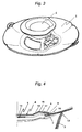
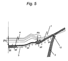
- Fig. 4 and Fig. 5 the operating principle of the device according to the invention is most clearly recognizable.
- the lower cover (1) placed on the selected food container (2).
- the passage opening (3) comes to lie within the container opening and the container edge is covered. So these are easy to follow restrictions.
- the upper cover (4) is first loosely placed on the lower cover (1) in such a way that the outermost lower edge line (7) of the upper cover (4) lie on the support surface (6) of the lower cover (6) comes and the contact area (11) of the upper cover (4) as possible over the support surface (6) of the lower cover (1). Since in this case the upper cover (4) circumferentially rests only along its outermost lower edge line (7) on the lower cover (1) is already a reliable seal and thus already created over conventional covers freshkeeping function.
- edge reinforcement region (8) extends beyond this line, ie it just covers the outer edge of the passage openings (3) in the applied state of the two covers (1, 4), the two covers (1, 4) remain attached to each other, especially after relieving the applied force (P1) more reliably.
- the lower cover (1) If the manually applied compressive force (P1) is gradually released, the lower cover (1) tries to return to its unstressed original position due to its elastic restoring force. However, since the passage openings (3) are closed by the upper cover (4) and the edge portion of the upper cover (4), as stated above, is actually fixed to the lower cover (1), the lower cover (1) succeeds only to a lesser extent towards the original position. This return movement causes an increasingly negative pressure (p2) to build up in the container (2) until an equilibrium has been established between said restoring force and the opposing suction force as a result of the increasing negative pressure (p2).
- the upper cover (4) is hereby also deformed, in particular stretched, but remains at least in the contact area (12) on the lower cover (1) adhere.
- the edge reinforcement region (8) of the upper cover (4) has a compensatory effect on different deformations or stress peaks of the lower cover (1) due to unevenly distributed passage openings (3) and / or over the circumference of varying radial cross-sectional configurations of the lower cover (1).
- the support surface (6) of the lower cover (1) For the reliability of the device, it is useful, in particular the support surface (6) of the lower cover (1), the contact area (11) of the upper cover (4), the contact line of the lower cover (1) with the upper edge of the container and the upper edge to keep the container (2) as clean as possible and free of disturbing conditions such as hair or food residues. It has been found that, in particular, the long-lasting reliability can be further enhanced by the fact that a channel (10) forms in the channel formed by the outer wall (9) of the upper cover (4) and the surface section of the lower cover (1) which is adjacent to the outside ), in which or water is introduced.
- the liquid in the liquid channel (10) serves as a sealant and the liquid itself can be characterized by the least Contaminants possibly forming, very narrow access path pieces do not penetrate, which would be possible for air.
Landscapes
- Engineering & Computer Science (AREA)
- Food Science & Technology (AREA)
- Closures For Containers (AREA)
Applications Claiming Priority (1)
| Application Number | Priority Date | Filing Date | Title |
|---|---|---|---|
| DE102012024996.9A DE102012024996B3 (de) | 2012-12-20 | 2012-12-20 | Vorrichtung zum Abdecken von Lebensmittelbehältern mit unterschiedlichen Öffnungsweiten und zum Frischhalten des Behälterinhaltes |
Publications (1)
| Publication Number | Publication Date |
|---|---|
| EP2745754A1 true EP2745754A1 (fr) | 2014-06-25 |
Family
ID=49000293
Family Applications (1)
| Application Number | Title | Priority Date | Filing Date |
|---|---|---|---|
| EP13004083.5A Withdrawn EP2745754A1 (fr) | 2012-12-20 | 2013-08-16 | Dispositif destiné au recouvrement de récipients pour produits alimentaires avec différentes largeurs d'ouverture et de maintien au froid du contenu des récipients |
Country Status (2)
| Country | Link |
|---|---|
| EP (1) | EP2745754A1 (fr) |
| DE (1) | DE102012024996B3 (fr) |
Cited By (1)
| Publication number | Priority date | Publication date | Assignee | Title |
|---|---|---|---|---|
| CN113271829A (zh) * | 2019-01-11 | 2021-08-17 | 双立人亨克斯股份公司 | 用于食品的保鲜负压容器 |
Families Citing this family (1)
| Publication number | Priority date | Publication date | Assignee | Title |
|---|---|---|---|---|
| CN110652213A (zh) * | 2019-10-12 | 2020-01-07 | 广东怡家实业投资有限公司 | 一种自动防溢盖 |
Citations (5)
| Publication number | Priority date | Publication date | Assignee | Title |
|---|---|---|---|---|
| US6105811A (en) * | 1999-07-29 | 2000-08-22 | Alfred; Greg | Ergonomic cooking pan cover |
| EP1666368A1 (fr) * | 2004-12-04 | 2006-06-07 | Sar Holdings International Limited | Couvercle intelligent |
| WO2007003210A1 (fr) | 2005-07-01 | 2007-01-11 | Cook-World Gmbh | Ustensile de cuisine |
| EP2008943A1 (fr) * | 2007-06-26 | 2008-12-31 | Giorgio Tosini | Couvercle flexible scellé contre les agents atmosphériques et procédé correspondant l'utilisant |
| US20110061544A1 (en) * | 2009-09-17 | 2011-03-17 | Armin Harecker | Cooking vessel top to prevent boil over of liquids |
-
2012
- 2012-12-20 DE DE102012024996.9A patent/DE102012024996B3/de not_active Expired - Fee Related
-
2013
- 2013-08-16 EP EP13004083.5A patent/EP2745754A1/fr not_active Withdrawn
Patent Citations (7)
| Publication number | Priority date | Publication date | Assignee | Title |
|---|---|---|---|---|
| US6105811A (en) * | 1999-07-29 | 2000-08-22 | Alfred; Greg | Ergonomic cooking pan cover |
| EP1666368A1 (fr) * | 2004-12-04 | 2006-06-07 | Sar Holdings International Limited | Couvercle intelligent |
| WO2007003210A1 (fr) | 2005-07-01 | 2007-01-11 | Cook-World Gmbh | Ustensile de cuisine |
| EP1755983A1 (fr) * | 2005-07-01 | 2007-02-28 | Cook-World GmbH | Ustensile de cuisine |
| EP2008943A1 (fr) * | 2007-06-26 | 2008-12-31 | Giorgio Tosini | Couvercle flexible scellé contre les agents atmosphériques et procédé correspondant l'utilisant |
| US20110061544A1 (en) * | 2009-09-17 | 2011-03-17 | Armin Harecker | Cooking vessel top to prevent boil over of liquids |
| DE102009041866B4 (de) | 2009-09-17 | 2012-01-12 | Armin Harecker | Kochgefäßaufsatz zum Verhüten des Überkochens von Flüssigkeiten |
Cited By (2)
| Publication number | Priority date | Publication date | Assignee | Title |
|---|---|---|---|---|
| CN113271829A (zh) * | 2019-01-11 | 2021-08-17 | 双立人亨克斯股份公司 | 用于食品的保鲜负压容器 |
| CN113271829B (zh) * | 2019-01-11 | 2024-03-12 | 双立人亨克斯股份公司 | 用于食品的保鲜负压容器 |
Also Published As
| Publication number | Publication date |
|---|---|
| DE102012024996B3 (de) | 2014-02-20 |
Similar Documents
| Publication | Publication Date | Title |
|---|---|---|
| EP0247406B1 (fr) | Marmite à pression munie d'un joint d'étanchéité | |
| DE19580254B4 (de) | Verschluss und Dichtelement | |
| EP2293990A1 (fr) | Dispositif de fermeture pour un récipient | |
| DE29618940U1 (de) | Dichtbehälter | |
| DE20006685U1 (de) | Vorrichtung zur Positionierung von Gegenständen | |
| WO2012003853A1 (fr) | Couvercle pour autocuiseur, et autocuiseur pourvu d'un couvercle | |
| DE69807273T2 (de) | Überdruckventil | |
| DE102009041866A1 (de) | Kochgefäßaufsatz zum Verhüten des Überkochens von Flüssigkeiten | |
| DE60202791T2 (de) | Behälter zur konservierung von produkten unter vakuum | |
| DE102012024996B3 (de) | Vorrichtung zum Abdecken von Lebensmittelbehältern mit unterschiedlichen Öffnungsweiten und zum Frischhalten des Behälterinhaltes | |
| DE2100480C3 (de) | Verschlußkappe für Saugflaschen | |
| EP0743036A1 (fr) | Récipient, en particulier marmite à pression, avec couvercle, accessoire de cuison à vapeur, bain-marie, accessoire de couper adaptés audit récipient | |
| DE102018125344A1 (de) | Verschlussvorrichtung für einen Tuchspender | |
| DE112005001247T5 (de) | Ein Überlaufen verhindernder Behälterdeckel | |
| WO2003064897A2 (fr) | Dispositif de fermeture pour recipient | |
| DE202008009728U1 (de) | Portionsbehälter mit Vorrichtung zum einfachen Öffnen | |
| DE102008025430A1 (de) | Verschlussvorrichtung für einen Behälter | |
| WO2009000542A1 (fr) | Élément de fermeture pour récipients | |
| DE102019115380B3 (de) | Vorrichtung zum Verschließen einer durch ein Randstück begrenzten Flaschenöffnung | |
| DE4143285C2 (de) | Springform für Backwaren | |
| DE602005005214T2 (de) | Ventile für trinkbecher | |
| CH690272A5 (de) | Aufsatzteil für Kehrichtbehälter, insbesondere für im Haushalt verwendete Kehrichtbehälter. | |
| EP1755983A1 (fr) | Ustensile de cuisine | |
| DE102023116831A1 (de) | Deckel, insbesondere für ein Brat- oder Kochgefäß | |
| EP3357378B1 (fr) | Récipient portatif pour aliments |
Legal Events
| Date | Code | Title | Description |
|---|---|---|---|
| PUAI | Public reference made under article 153(3) epc to a published international application that has entered the european phase |
Free format text: ORIGINAL CODE: 0009012 |
|
| 17P | Request for examination filed |
Effective date: 20130816 |
|
| AK | Designated contracting states |
Kind code of ref document: A1 Designated state(s): AL AT BE BG CH CY CZ DE DK EE ES FI FR GB GR HR HU IE IS IT LI LT LU LV MC MK MT NL NO PL PT RO RS SE SI SK SM TR |
|
| AX | Request for extension of the european patent |
Extension state: BA ME |
|
| STAA | Information on the status of an ep patent application or granted ep patent |
Free format text: STATUS: THE APPLICATION IS DEEMED TO BE WITHDRAWN |
|
| 18D | Application deemed to be withdrawn |
Effective date: 20150106 |