EP2746510A2 - Scharnier - Google Patents
Scharnier Download PDFInfo
- Publication number
- EP2746510A2 EP2746510A2 EP13005193.1A EP13005193A EP2746510A2 EP 2746510 A2 EP2746510 A2 EP 2746510A2 EP 13005193 A EP13005193 A EP 13005193A EP 2746510 A2 EP2746510 A2 EP 2746510A2
- Authority
- EP
- European Patent Office
- Prior art keywords
- hinge
- lever
- damper
- coupling
- damping
- Prior art date
- Legal status (The legal status is an assumption and is not a legal conclusion. Google has not performed a legal analysis and makes no representation as to the accuracy of the status listed.)
- Granted
Links
Images
Classifications
-
- E—FIXED CONSTRUCTIONS
- E05—LOCKS; KEYS; WINDOW OR DOOR FITTINGS; SAFES
- E05F—DEVICES FOR MOVING WINGS INTO OPEN OR CLOSED POSITION; CHECKS FOR WINGS; WING FITTINGS NOT OTHERWISE PROVIDED FOR, CONCERNED WITH THE FUNCTIONING OF THE WING
- E05F5/00—Braking devices, e.g. checks; Stops; Buffers
- E05F5/006—Braking devices, e.g. checks; Stops; Buffers for hinges having a cup-shaped fixing part, e.g. for attachment to cabinets or furniture
-
- E—FIXED CONSTRUCTIONS
- E05—LOCKS; KEYS; WINDOW OR DOOR FITTINGS; SAFES
- E05D—HINGES OR SUSPENSION DEVICES FOR DOORS, WINDOWS OR WINGS
- E05D3/00—Hinges with pins
- E05D3/06—Hinges with pins with two or more pins
-
- E—FIXED CONSTRUCTIONS
- E05—LOCKS; KEYS; WINDOW OR DOOR FITTINGS; SAFES
- E05D—HINGES OR SUSPENSION DEVICES FOR DOORS, WINDOWS OR WINGS
- E05D3/00—Hinges with pins
- E05D3/06—Hinges with pins with two or more pins
- E05D3/16—Hinges with pins with two or more pins with seven parallel pins and four arms
-
- E—FIXED CONSTRUCTIONS
- E05—LOCKS; KEYS; WINDOW OR DOOR FITTINGS; SAFES
- E05Y—INDEXING SCHEME ASSOCIATED WITH SUBCLASSES E05D AND E05F, RELATING TO CONSTRUCTION ELEMENTS, ELECTRIC CONTROL, POWER SUPPLY, POWER SIGNAL OR TRANSMISSION, USER INTERFACES, MOUNTING OR COUPLING, DETAILS, ACCESSORIES, AUXILIARY OPERATIONS NOT OTHERWISE PROVIDED FOR, APPLICATION THEREOF
- E05Y2201/00—Constructional elements; Accessories therefor
- E05Y2201/20—Brakes; Disengaging means; Holders; Stops; Valves; Accessories therefor
- E05Y2201/21—Brakes
-
- E—FIXED CONSTRUCTIONS
- E05—LOCKS; KEYS; WINDOW OR DOOR FITTINGS; SAFES
- E05Y—INDEXING SCHEME ASSOCIATED WITH SUBCLASSES E05D AND E05F, RELATING TO CONSTRUCTION ELEMENTS, ELECTRIC CONTROL, POWER SUPPLY, POWER SIGNAL OR TRANSMISSION, USER INTERFACES, MOUNTING OR COUPLING, DETAILS, ACCESSORIES, AUXILIARY OPERATIONS NOT OTHERWISE PROVIDED FOR, APPLICATION THEREOF
- E05Y2201/00—Constructional elements; Accessories therefor
- E05Y2201/20—Brakes; Disengaging means; Holders; Stops; Valves; Accessories therefor
- E05Y2201/252—Type of friction
- E05Y2201/254—Fluid or viscous friction
-
- E—FIXED CONSTRUCTIONS
- E05—LOCKS; KEYS; WINDOW OR DOOR FITTINGS; SAFES
- E05Y—INDEXING SCHEME ASSOCIATED WITH SUBCLASSES E05D AND E05F, RELATING TO CONSTRUCTION ELEMENTS, ELECTRIC CONTROL, POWER SUPPLY, POWER SIGNAL OR TRANSMISSION, USER INTERFACES, MOUNTING OR COUPLING, DETAILS, ACCESSORIES, AUXILIARY OPERATIONS NOT OTHERWISE PROVIDED FOR, APPLICATION THEREOF
- E05Y2201/00—Constructional elements; Accessories therefor
- E05Y2201/20—Brakes; Disengaging means; Holders; Stops; Valves; Accessories therefor
- E05Y2201/252—Type of friction
- E05Y2201/254—Fluid or viscous friction
- E05Y2201/256—Fluid or viscous friction with pistons or vanes
-
- E—FIXED CONSTRUCTIONS
- E05—LOCKS; KEYS; WINDOW OR DOOR FITTINGS; SAFES
- E05Y—INDEXING SCHEME ASSOCIATED WITH SUBCLASSES E05D AND E05F, RELATING TO CONSTRUCTION ELEMENTS, ELECTRIC CONTROL, POWER SUPPLY, POWER SIGNAL OR TRANSMISSION, USER INTERFACES, MOUNTING OR COUPLING, DETAILS, ACCESSORIES, AUXILIARY OPERATIONS NOT OTHERWISE PROVIDED FOR, APPLICATION THEREOF
- E05Y2201/00—Constructional elements; Accessories therefor
- E05Y2201/20—Brakes; Disengaging means; Holders; Stops; Valves; Accessories therefor
- E05Y2201/262—Type of motion, e.g. braking
- E05Y2201/264—Type of motion, e.g. braking linear
-
- E—FIXED CONSTRUCTIONS
- E05—LOCKS; KEYS; WINDOW OR DOOR FITTINGS; SAFES
- E05Y—INDEXING SCHEME ASSOCIATED WITH SUBCLASSES E05D AND E05F, RELATING TO CONSTRUCTION ELEMENTS, ELECTRIC CONTROL, POWER SUPPLY, POWER SIGNAL OR TRANSMISSION, USER INTERFACES, MOUNTING OR COUPLING, DETAILS, ACCESSORIES, AUXILIARY OPERATIONS NOT OTHERWISE PROVIDED FOR, APPLICATION THEREOF
- E05Y2800/00—Details, accessories and auxiliary operations not otherwise provided for
- E05Y2800/73—Multiple functions
-
- E—FIXED CONSTRUCTIONS
- E05—LOCKS; KEYS; WINDOW OR DOOR FITTINGS; SAFES
- E05Y—INDEXING SCHEME ASSOCIATED WITH SUBCLASSES E05D AND E05F, RELATING TO CONSTRUCTION ELEMENTS, ELECTRIC CONTROL, POWER SUPPLY, POWER SIGNAL OR TRANSMISSION, USER INTERFACES, MOUNTING OR COUPLING, DETAILS, ACCESSORIES, AUXILIARY OPERATIONS NOT OTHERWISE PROVIDED FOR, APPLICATION THEREOF
- E05Y2900/00—Application of doors, windows, wings or fittings thereof
- E05Y2900/20—Application of doors, windows, wings or fittings thereof for furniture, e.g. cabinets
Definitions
- the invention relates to a hinge for a movable furniture part fastened to a furniture body of a piece of furniture, in particular a door or a flap, wherein the hinge has a first hinge part which can be fastened to the movable furniture part and which has an articulated lever mechanism with a second hinge part which can be fastened to the furniture body between an opening. and a closed position is pivotally connected, wherein the toggle mechanism comprises articulated levers mounted via hinge axes, and wherein the hinge has a damping device.
- Such a hinge is for example from the DE 10 2010 006 816 A1 known.
- This hinge has a damper arrangement, which reaches a damped or decelerated movement in an end position of the pivoting operation carried out with the hinge in a proper pivoting movement of the hinge. This can be avoided in the furniture-mounted state of the hinge an undesirably strong slamming of the movable furniture part, in particular an unpleasant surcharge noise or damage to the furniture part and the carcass.
- the object of the invention is to provide a hinge of the type mentioned, which is universally applicable and with which by means of the damping device an optimal Can achieve damping of coupled with the hinge furniture part.
- the hinge according to the invention is characterized in that the coupling mechanism having a coupling means is associated with the coupling mechanism, which is coupled to the damping device such that the damping acts both in the closing direction and in the opening direction of the first hinge part.
- a hinge with integrated damping device which damps both the retraction of the movable furniture part in the closed position and the extension into the open position. Due to the damping in the closing direction, the aforementioned strong slamming of the movable furniture part can be avoided.
- the hinge according to the invention still has an additional function, namely the damping device also dampens in the opening direction. This can prevent unwanted strong opening of the movable furniture part. In particular, this should prevent a hard stop in the open position, which can lead to damage to the hinge or the movable furniture part.
- the damping is a cushioning.
- the movable furniture part can thus be fully moved despite damping in the open position and in the closed position.
- the damping device has at least one damper, which takes over both the damping in the closing direction and the damping in the opening direction.
- the damper has two damper components movable relative to each other, one of which is coupled via the coupling means to the toggle mechanism and thus to the movement of the first hinge part.
- damping in the closing clearing and the damping in the opening direction take place in the same direction of movement of the damper component coupled to the first hinge part. This also has a positive effect on the size of the hinge, since the stroke of the damper component always goes in the same direction, regardless of the direction of movement of the hinge.
- damping in the closing direction and the damping in the opening direction takes place in mutually different directions of movement of the coupled to the first hinge part damper component, for example, the moving damper component when damping in the closing direction in the one and when damping in the opening direction in the opposite direction moves.
- the coupling means on a plurality of mutually motion-coupled coupling links exhibiting coupling gear, which is coupled on the one hand with the hinge mechanism and on the other hand with the damping device.
- the coupling gear as a lifting gear and the coupling members are designed as articulated interconnected coupling lever.
- other types of coupling gears are used, for example, gear transmission, however, is designed as a lever gear coupling gear particularly by the simple design and cost-effective production.
- the lever mechanism has a crank mechanism formed by the coupling levers, wherein preferably a crank in the form of a lever arrangement is provided, which has two hingedly interconnected via a hinge lever parts, of which a first lever member is pivotally mounted on a stationary hinge axis and a second lever member pivotally coupled to an articulated lever of the articulated lever mechanism in the opening or closing movement of the first hinge member is arcuately pivoted about a fixed pivot axis of another coupling lever such that the articulation performs a reversing motion via the further coupling levers formed as transmission members the damper component is transferable to generate the damping.
- the first lever part of the lever assembly is extended beyond the fixed hinge axis out and has at its end another hinge axis to which an intermediate lever is articulated, which in turn is pivotally connected to a pivot lever.
- the pivot lever is pivotally mounted about the fixed pivot axis about which the second lever part of the lever assembly is circular arc, wherein the pivot lever has a third hinge axis, via which a further coupling lever is articulated, which in turn is coupled to the damper component ,
- the further coupling lever can be configured, for example, in the manner of a coupling rod.
- the damper is arranged on the second hinge part.
- the damper thus sits on the stationary, attachable to the furniture body second hinge part.
- the damper is designed as a fluid damper.
- a gas in particular air damper is suitable.
- a hydraulic damper such as hydraulic oil damper would be used.
- the damping device has a mechanical and / or motorized brake element, which causes the damping effect in the form of deceleration of the movement in the closing and in the opening direction.
- the damper is designed as a piston damper and damper components in the form of a damper piston and a damper housing, which are movable relative to each other.
- a design as a piston damper is particularly useful in fluid dampers.
- the damper component coupled to the first hinge part is the damper housing, which in turn is movably guided on the second hinge part is.
- the damper housing moves while the damper piston remains stationary.
- the invention further comprises a piece of furniture, with a piece of furniture which can be fastened to the furniture body of the piece of furniture, in particular a door or flap, wherein the piece of furniture has a hinge according to one of claims 1 to 14.
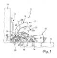
- FIGS. 1 to 3 show a preferred embodiment of the hinge 11 according to the invention.
- the hinge 11 is formed as a so-called wide-angle or universal joint hinge.
- the hinge 11 comprises a first hinge part 12, which can be moved on a hinge 11 on a furniture carcass 13th accommodated movable furniture part 14 is fastened.
- the movable furniture part 14 may be formed, for example, as a door or flap.
- the hinge 11 further comprises a second hinge part 15 which is attachable to the furniture body 13.
- the first movable hinge member 12 includes a hinge plate 16 which is adapted to be selectively attached to a wooden or glass or mirrors formed door or flap.
- the hinge part can also be designed as a hinge cup. The attachment of the first hinge part 12 can take place without tools via suitable fastening means, for example fastening screws or via quick-fastening means.
- the attachment of the second, fixed hinge part 15 can also be done without tools on the inside of a furniture compartment formed in a furniture compartment by means of suitable fastening means, such as fastening screws or quick fasteners.
- the two hinge parts 12, 15 are pivotally connected to each other via a toggle mechanism 17 to each other.
- the toggle mechanism includes a plurality of articulated levers mounted about hinge axes.
- the toggle mechanism is designed as a whole as a kinematic chain in the form of a seven-joint.
- a first articulated lever 18 is provided which has two articulated lever parts 20a, 20b which are interconnected by a hinge 19. This is a first Articulated lever part 20a connected via a fixed hinge axis 21 pivotally connected to the stationary second hinge part 15 and coupled via the hinge 19 hinged to a second articulated lever part 20b, which in turn is pivotally mounted via a further pivot axis 22 on the movable first hinge part and there on the hinge plate 16.
- a second articulated lever 23 which also has two articulated lever parts 25a, 25b which are interconnected via a joint 24.
- a first articulated lever part 25a in turn is pivotally mounted on a stationary pivot axis 26 on the second hinge part 15.
- the first articulated lever part 25a is connected via the joint 24 to the second articulated lever part 25b, which in turn is mounted pivotably on the first hinge part 12 or there on the hinge plate 16 via a further pivot axis 27.
- the two articulated levers 18, 23 are additionally pivotally coupled to one another via a central joint 28.
- the first articulated lever part 20a of the first articulated lever 18 is pivotally coupled to the second articulated lever part 25b of the second articulated lever 23.
- the coupling mechanism 29 is associated with the articulated lever mechanism 17, which is coupled with a damping device 30, which likewise belongs to the hinge 11, such that the damping acts both in the closing direction and in the opening direction of the first hinge part 12.
- the damping device 30 has a damper 31 designed as a fluid damper.
- the damper 31 is arranged on the stationary second hinge part 15.
- the damper 31 is housed in a hinge part housing 32 of the second hinge part 15.
- the damper 31 is designed as a piston damper whose damping effect is achieved by a Dämpffluid, such as air or hydraulic oil.
- the damper 31 basically has two damper components, of which a damper component is coupled via the coupling device 29 to the articulated lever mechanism 17 and is therefore moved in the pivoting movement of the first hinge part 12 relative to the other damper component.
- the damper 31 has a damper housing 33, which is coupled as a movable damper component to the toggle mechanism 17.
- the damper housing 33 is slidably guided in the hinge part housing 32. In the damper housing 33 is the aforementioned Dämpffluid.
- damper piston 34 As a second damper component, which is arranged stationary in the example, serves a damper piston 34.
- the damper piston 34 is attached via suitable fastening means on the hinge part housing 32.
- the movable damper housing 33 passes over the damper piston 34 such that the damper piston 34 dips into the damper housing 33 and displaces the damping fluid located there.
- the coupling device 29 comprises coupling means, which have a coupling mechanism 35 having a plurality of coupling elements coupled with each other in a motion-coupled manner.
- the coupling gear is coupled on the one hand with the toggle mechanism 17 and on the other hand with the damping device 30.
- the coupling mechanism is designed as a lever mechanism, wherein the coupling members are formed as articulated interconnected coupling lever.
- the coupling mechanism in the form of the lever mechanism has a crank mechanism 36 formed from the coupling levers.
- the crank mechanism 36 comprises a crank 37 in the form of a lever arrangement, the two hinged together via a hinge 38 Lever parts 39, 40 has.
- a first lever member 39 is pivotally mounted on a stationary hinge axis 41.
- a second lever part 40 is provided, which is coupled via a further joint 42 articulated to the second articulated lever 23 of the toggle mechanism.
- the further joint 42 is located on the first articulated lever part 25a of the second articulated lever 23.
- the second lever part 40 is pivoted in a circular arc around the fixed pivot axis 26 of the first articulated lever part 25a of the second articulated lever 23 during the opening or closing movement of the first hinge part 12 Joint 42 performs a reversing motion.
- the first lever part 39 is extended beyond the fixed joint 41 and has at its end another joint axis 43, to which an intermediate lever 44 is articulated, which in turn is articulated via a further hinge axis 45 with a pivot lever 46.
- the pivot lever 46 is pivotally mounted about the fixed pivot axis 26 of the first articulated lever part 25a of the second articulated lever 23, wherein the pivot lever 46 has a third articulation axis 47, via which a further coupling lever 48 is articulated in the form of a coupling rod.
- the coupling rod in turn is attached to the damper housing 33, so that ultimately the pivoting movement of the first hinge part 12 is transmitted via the coupling device 29 to the damper housing 33, which performs a damping stroke described in more detail below.
- FIG. 1 shows the closed position of the first hinge part 12 and thus the closed position of the coupled to the first hinge part 12 movable furniture part 14 in the form of a door leaf or a flap.
- the first hinge part pivots 25a of the second articulated lever 23 about the stationary pivot axis 26. Since the crank 37 of the crank mechanism 36 of the linkage 35 coupled to the pivotal movement of the second articulated lever 23 is, the joint 42, which is located on the first articulated lever part 25a, a circular arc about the fixed pivot axis 26 is pivoted.
- the joint 42 is part of the second lever part 40, wherein the arcuate pivoting of the joint 42 presses the joint 38 between the two lever parts 39, 40 to the outside.
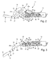
- FIGS. 2 and 3 shows the further movement of the movable first hinge part 12 to the open position. It is characteristic that the crank 37 of the crank mechanism 36 with its joint 42 continues to pivot about the fixed pivot axis 26 in a circular arc shape. Since the lever length of the second lever part 40 does not change, the joint 38 between the two lever parts 39, 40 becomes a reversing Movement forced, ie, the joint 38 is moved back toward the second hinge part 15. This causes a pivoting of the first lever member in the clockwise direction about the fixed hinge axis 41. This in turn causes the intermediate lever 44 is pulled away from the second hinge part 15 to the front. This in turn leads to a pivoting of the pivot lever 46 about the stationary pivot axis 26 in the clockwise direction.
Landscapes
- Engineering & Computer Science (AREA)
- Mechanical Engineering (AREA)
- Hinges (AREA)
Abstract
Description
- Die Erfindung betrifft ein Scharnier für ein an einem Möbelkorpus eines Möbels befestigtes bewegbares Möbelteil, insbesondere eine Tür oder eine Klappe, wobei das Scharnier ein am bewegbaren Möbelteil befestigbares erstes Scharnierteil aufweist, das über einen Gelenkhebelmechanismus mit einem am Möbelkorpus befestigbaren zweiten Scharnierteil zwischen einer Öffnungs- und einer Schließstellung verschwenkbar verbunden ist, wobei der Gelenkhebelmechanismus über Gelenkachsen gelagerte Gelenkhebel umfasst, und wobei das Scharnier eine Dämpfungseinrichtung aufweist.
- Ein derartiges Scharnier ist beispielsweise aus der
DE 10 2010 006 816 A1 bekannt. Dieses Scharnier besitzt eine Dämpferanordnung, die bei einer bestimmungsgemäßen Schwenkbewegung des Scharniers eine gedämpfte bzw. abgebremste Bewegung in eine Endlage des mit dem Scharnier ausgeführten Schwenkvorgangs erreicht. Damit lässt sich im am Möbel montierten Zustand des Scharniers ein unterwünscht starkes Zuschlagen des bewegbaren Möbelteils vermeiden, insbesondere ein unangenehmes Zuschlaggeräusch bzw. eine Beschädigung am Möbelteil und am Korpus. - Aufgabe der Erfindung ist es, ein Scharnier der eingangs erwähnten Art zu schaffen, das universell einsetzbar ist und mit dem sich mittels der Dämpfungseinrichtung eine optimale Dämpfung des mit dem Scharnier gekoppelten Möbelteils erzielen lässt.
- Diese Aufgabe wird durch ein Scharnier mit den Merkmalen des unabhängigen Anspruchs 1 gelöst. Weiterbildungen der Erfindung sind in den Unteransprüchen dargestellt.
- Das erfindungsgemäße Scharnier zeichnet sich dadurch aus, dass dem Gelenkhebelmechanismus eine Koppelmittel aufweisende Koppeleinrichtung zugeordnet ist, die derart mit der Dämpfungseinrichtung gekoppelt ist, dass die Dämpfung sowohl in der Schließrichtung als auch in der Öffnungsrichtung des ersten Scharnierteils wirkt.
- Somit wird ein Scharnier mit integrierter Dämpfungseinrichtung geschaffen, die sowohl das Einfahren des bewegbaren Möbelteils in die Schließstellung als auch das Ausfahren in die Öffnungsstellung dämpft. Durch die Dämpfung in Schließrichtung lässt sich das vorerwähnte starke Zuschlagen des bewegbaren Möbelteils vermeiden. Das erfindungsgemäße Scharnier besitzt jedoch noch eine Zusatzfunktion, nämlich die Dämpfungseinrichtung dämpft auch in der Öffnungsrichtung. Damit lässt sich ein unerwünschtes starkes Öffnen des bewegbaren Möbelteils verhindern. Insbesondere soll dadurch ein harter Anschlag in die Öffnungsstellung verhindert werden, was zu Beschädigungen am Scharnier oder am bewegbaren Möbelteil führen kann.
- Zweckmäßigerweise handelt es sich bei der Dämpfung um eine Endlagendämpfung. Das bewegbare Möbelteil kann also trotz Dämpfung vollständig in die Öffnungsstellung und in die Schließstellung bewegt werden.
- Bei einer Weiterbildung der Erfindung weist die Dämpfungseinrichtung wenigstens einen Dämpfer auf, der sowohl die Dämpfung in Schließrichtung als auch die Dämpfung in Öffnungsrichtung übernimmt.
- Es wirkt also derselbe Dämpfer in beide Richtungen, also sowohl in der Schließ- als auch in der Öffnungsrichtung. Grundsätzlich ist es möglich, dass ein einziger Dämpfer zur Dämpfung in der Schließ- und zur Dämpfung in der Öffnungsrichtung ausreicht. Obwohl also in beide Richtungen gedämpft wird, kommt das Scharnier in diesem Fall mit einem Dämpfer aus, was sich positiv auf die Baugröße des Scharniers auswirkt.
- Bei einer Weiterbildung der Erfindung besitzt der Dämpfer zwei relativ zueinander bewegbare Dämpferkomponenten, von denen eine über die Koppelmittel an den Gelenkhebelmechanismus und damit an die Bewegung des ersten Scharnierteils angekoppelt ist.
- Es ist möglich, dass die Dämpfung in Schließlichtung und die Dämpfung in Öffnungsrichtung in derselben Bewegungsrichtung der an das erste Scharnierteil angekoppelten Dämpferkomponente erfolgt. Auch dies wirkt sich positiv auf die Baugröße des Scharniers aus, da der Hub der Dämpferkomponente unabhängig von der Bewegungsrichtung des Scharniers immer in dieselbe Richtung geht. Grundsätzlich wäre es jedoch auch möglich, dass die Dämpfung in Schließrichtung und die Dämpfung in Öffnungsrichtung in voneinander verschiedenen Bewegungsrichtungen der an das erste Scharnierteil angekoppelten Dämpferkomponente erfolgt, beispielsweise das sich die bewegte Dämpferkomponente beim Dämpfen in Schließrichtung in die eine und beim Dämpfen in die Öffnungsrichtung in die entgegengesetzte andere Richtung bewegt.
- Bei einer Weiterbildung der Erfindung weisen die Koppelmittel ein mehrere miteinander bewegungsgekoppelte Koppelglieder aufweisendes Koppelgetriebe auf, das einerseits mit dem Gelenkmechanismus und andererseits mit der Dämpfungseinrichtung gekoppelt ist.
- In besonders bevorzugter Weise sind das Koppelgetriebe als Hebegetriebe und die Koppelglieder als gelenkig miteinander verbundene Koppelhebel ausgebildet. Grundsätzlich sind jedoch auch andere Arten von Koppelgetrieben einsetzbar, beispielsweise Zahnradgetriebe, jedoch zeichnet sich ein als Hebelgetriebe ausgebildetes Koppelgetriebe besonders durch die einfache Bauart und die kostengünstige Herstellung aus.
- Bei einer Weiterbildung der Erfindung weist das Hebelgetriebe einen aus den Koppelhebeln gebildeten Kurbeltrieb auf, wobei vorzugsweise eine Kurbel in Form einer Hebelanordnung vorgesehen ist, die zwei über ein Gelenk gelenkig miteinander verbundene Hebelteile aufweist, von denen ein erstes Hebelteil an einer ortsfesten Gelenkachse schwenkbar gelagert ist und ein, gelenkig mit einem Gelenkhebel des Gelenkhebelmechanismus gekoppeltes, zweites Hebelteil bei der Öffnungs- oder Schließbewegung des ersten Scharnierteils kreisbogenförmig um eine ortsfeste Schwenkachse eines anderen Koppelhebels derart verschwenkt wird, dass das Gelenk eine reversierende Bewegung ausführt, die über als Übertragungsglieder ausgebildete weitere Koppelhebel auf die Dämpferkomponente zur Erzeugung der Dämpfung übertragbar ist.
- Zweckmäßigerweise ist das erste Hebelteil der Hebelanordnung über die ortsfeste Gelenkachse hinaus verlängert und besitzt endseitig eine weitere Gelenkachse, an der ein Zwischenhebel angelenkt ist, das seinerseits gelenkig mit einem Schwenkhebel verbunden ist.
- Bei einer Weiterbildung der Erfindung ist der Schwenkhebel um die ortsfeste Schwenkachse schwenkbar gelagert, um die das zweite Hebelteil der Hebelanordnung kreisbogenförmig verschwenkbar ist, wobei der Schwenkhebel über eine dritte Gelenkachse verfügt, über die ein weiterer Koppelhebel angelenkt ist, der seinerseits an die Dämpferkomponente angekoppelt ist. Der weitere Koppelhebel kann beispielsweise nach Art einer Koppelstange ausgestaltet sein.
- Bei einer Weiterbildung der Erfindung ist der Dämpfer am zweiten Scharnierteil angeordnet. In diesem Fall sitzt der Dämpfer also am ortsfesten, am Möbelkorpus befestigbaren zweiten Scharnierteil. Es ist jedoch auch möglich, den Dämpfer dem ersten Scharnierteil zuzuordnen, insbesondere diesen am ersten Scharnierteil anzuordnen.
- Es ist möglich, dass der Dämpfer als Fluiddämpfer ausgebildet ist. Hier eignet sich beispielsweise ein Gas-, insbesondere Luftdämpfer. Alternativ wäre jedoch auch ein Hydraulikdämpfer, beispielsweise Hydrauliköldämpfer einsetzbar. Es ist jedoch auch möglich, dass die Dämpfungseinrichtung ein mechanisches und/oder motorisches Bremselement besitzt, das die Dämpfwirkung in Form des Abbremsens der Bewegung in Schließund in Öffnungsrichtung bewirkt.
- Es ist möglich, dass der Dämpfer als Kolbendämpfer ausgestaltet ist und Dämpferkomponenten in Form eines Dämpferkolbens und eines Dämpfergehäuses aufweist, die relativ zueinander beweglich sind. Eine derartige Ausgestaltung als Kolbendämpfer ist besonders bei Fluiddämpfern zweckmäßig.
- Bei einer Weiterbildung der Erfindung ist die an das erste Scharnierteil angekoppelte Dämpferkomponente das Dämpfergehäuse, das seinerseits bewegbar am zweiten Scharnierteil geführt ist. In diesem Fall bewegt sich also das Dämpfergehäuse, während der Dämpferkolben ortsfest verbleibt. Es ist jedoch auch möglich, den Dämpferkolben den Dämpfungshub ausführen zu lassen, während das Dämpfergehäuse ortsfest ist.
- Die Erfindung umfasst ferner ein Möbel, mit einem am Möbelkorpus des Möbels befestigbaren Möbelteil, insbesondere Tür oder Klappe, wobei das Möbel ein Scharnier nach einem der Ansprüche 1 bis 14 aufweist.
- Ein bevorzugtes Ausführungsbeispiel ist in der Zeichnung dargestellt und wird im Folgenden näher erläutert. In der Zeichnung zeigen:
- Figur 1
- eine teilweise geschnittene Seitenansicht auf ein bevorzugtes Ausführungsbeispiel des erfindungsgemäßen Scharniers, wobei sich das erste bewegliche Scharnierteil in der Schließstellung befindet,
- Figur 2
- das Scharnier von
Figur 1 , wobei sich das bewegliche erste Scharnierteil in einer Zwischenstellung befindet und - Figur 3
- das Scharnier von
Figur 1 , wobei sich das bewegliche erste Scharnierteil in der Öffnungsstellung befindet. - Die
Figuren 1 bis 3 zeigen ein bevorzugtes Ausführungsbeispiel des erfindungsgemäßen Scharniers 11. Das Scharnier 11 ist als sogenanntes Weitwinkel- bzw. Kreuzgelenkscharnier ausgebildet. - Das Scharnier 11 umfasst ein erstes Scharnierteil 12, das an einem über das Scharnier 11 bewegbar an einem Möbelkorpus 13 aufgenommenes bewegbares Möbelteil 14 befestigbar ist. Das bewegbare Möbelteil 14 kann beispielsweise als Türflügel oder Klappe ausgebildet sein. Das Scharnier 11 umfasst ferner ein zweites Scharnierteil 15, das am Möbelkorpus 13 befestigbar ist.
- Wie in den
Figuren 1 bis 3 dargestellt, umfasst das erste, bewegliche Scharnierteil 12 eine Scharnierplatte 16, die dazu geeignet ist, wahlweise an einem/einer aus Holz, Glas oder als Spiegel ausgebildeten Türflügel oder Klappe befestigt zu werden. Im Falle eines aus Holz bestehenden bewegbaren Möbelteils kann das Scharnierteil auch als Scharniertopf ausgebildet sein. Die Befestigung des ersten Scharnierteils 12 kann über geeignetes Befestigungsmittel, beispielsweise Befestigungsschrauben oder über Schnellbefestigungsmittel werkzeuglos erfolgen. - Die Befestigung des zweiten, ortsfesten Scharnierteils 15 kann an der Innenseite eines in einem Möbelkorpus ausgebildeten Möbelfachs ebenfalls mittels geeigneter Befestigungsmittel, beispielsweise Befestigungsschrauben oder über Schnellbefestigungsmittel werkzeuglos erfolgen.
- Die beiden Scharnierteile 12, 15 sind über einen Gelenkhebelmechanismus 17 zueinander schwenkbar miteinander verbunden.
- Der Gelenkhebelmechanismus umfasst mehrere über Gelenkachsen gelagerte Gelenkhebel.
- Wie insbesondere in
Figur 2 dargestellt, ist der Gelenkhebelmechanismus insgesamt als kinematische Kette in Form eines Sieben-Gelenks ausgeführt. Es ist ein erster Gelenkhebel 18 vorgesehen, der zwei durch ein Gelenk 19 miteinander verbundene Gelenkhebelteile 20a, 20b aufweist. Dabei ist ein erstes Gelenkhebelteil 20a über eine ortsfeste Gelenkachse 21 schwenkbar am ortsfesten zweiten Scharnierteil 15 verbunden und über das Gelenk 19 gelenkig mit einem zweiten Gelenkhebelteil 20b gekoppelt, das seinerseits über eine weitere Schwenkachse 22 schwenkbar am beweglichen ersten Scharnierteil und dort an der Scharnierplatte 16 gelagert ist. - Ferner ist ein zweiter Gelenkhebel 23 vorgesehen, der ebenfalls zwei über ein Gelenk 24 miteinander verbundene Gelenkhebelteile 25a, 25b aufweist. Hierbei ist ein erstes Gelenkhebelteil 25a wiederum an einer ortsfesten Schwenkachse 26 schwenkbar am zweiten Scharnierteil 15 gelagert. Das erste Gelenkhebelteil 25a ist über das Gelenk 24 mit dem zweiten Gelenkhebelteil 25b verbunden, das wiederum über eine weitere Schwenkachse 27 schwenkbar am ersten Scharnierteil 12 bzw. dort an der Scharnierplatte 16 gelagert ist. Die beiden Gelenkhebel 18, 23 sind zusätzlich noch über ein Mittelgelenk 28 schwenkbar aneinander gekoppelt. Im Beispielsfall ist hier das erste Gelenkhebelteil 20a des ersten Gelenkhebels 18 schwenkbar an das zweite Gelenkhebelteil 25b des zweiten Gelenkhebels 23 angekoppelt.
- Wie insbesondere in den
Figuren 1 bis 3 dargestellt, ist dem Gelenkhebelmechanismus 17 eine Koppelmittel aufweisende Koppeleinrichtung 29 zugeordnet, die derart mit einer ebenfalls zum Scharnier 11 gehörenden Dämpfungseinrichtung 30 gekoppelt ist, dass die Dämpfung sowohl in der Schließrichtung als auch in der Öffnungsrichtung des ersten Scharnierteils 12 wirkt. Die Dämpfungseinrichtung 30 besitzt im Beispielsfall einen als Fluiddämpfer ausgebildeten Dämpfer 31. Der Dämpfer 31 ist am ortsfesten zweiten Scharnierteil 15 angeordnet. Insbesondere ist der Dämpfer 31 in einem Scharnierteilgehäuse 32 des zweiten Scharnierteils 15 untergebracht. - Wie insbesondere in
Figur 2 zu erkennen, ist der Dämpfer 31 als Kolbendämpfer ausgestaltet, dessen Dämpfwirkung durch ein Dämpffluid, beispielsweise Luft oder Hydrauliköl erzielt wird. Der Dämpfer 31 verfügt grundsätzlich über zwei Dämpferkomponenten, von denen eine Dämpferkomponente über die Koppeleinrichtung 29 an den Gelenkhebelmechanismus 17 angekoppelt ist und daher bei der Schwenkbewegung des ersten Scharnierteils 12 gegenüber der anderen Dämpferkomponente bewegt wird. Im Beispielsfall verfügt der Dämpfer 31 über ein Dämpfergehäuse 33, das als bewegliche Dämpferkomponente an den Gelenkhebelmechanismus 17 angekoppelt ist. Das Dämpfergehäuse 33 ist verschieblich im Scharnierteilgehäuse 32 geführt. Im Dämpfergehäuse 33 befindet sich das vorerwähnte Dämpffluid. Als zweite Dämpferkomponente, die im Beispielsfall ortsfest angeordnet ist, dient ein Dämpferkolben 34. Der Dämpferkolben 34 ist über geeignete Befestigungsmittel am Scharnierteilgehäuse 32 befestigt. Zur Erzeugung einer Dämpfwirkung überfährt das bewegliche Dämpfergehäuse 33 den Dämpferkolben 34 derart, dass der Dämpferkolben 34 in das Dämpfergehäuse 33 eintaucht und das dort befindliche Dämpffluid verdrängt. - Die Koppeleinrichtung 29 umfasst Koppelmittel, die ein mehrere miteinander bewegungsgekoppelte Koppelglieder aufweisendes Koppelgetriebe 35 aufweisen. Das Koppelgetriebe ist einerseits mit dem Gelenkhebelmechanismus 17 und andererseits mit der Dämpfungseinrichtung 30 gekoppelt. Im Beispielsfall ist das Koppelgetriebe als Hebelgetriebe ausgebildet, wobei die Koppelglieder als gelenkig miteinander verbundene Koppelhebel ausgebildet sind.
- Das Koppelgetriebe in Form des Hebelgetriebes weist einen aus den Koppelhebeln gebildeten Kurbeltrieb 36 auf. Der Kurbeltrieb 36 umfasst eine Kurbel 37 in Form einer Hebelanordnung, die zwei über ein Gelenk 38 gelenkig miteinander verbundene Hebelteile 39, 40 aufweist. Hiervon ist ein erstes Hebelteil 39 an einer ortsfesten Gelenkachse 41 schwenkbar gelagert. Ferner ist ein zweites Hebelteil 40 vorgesehen, das über ein weiteres Gelenk 42 gelenkig an den zweiten Gelenkhebel 23 des Gelenkhebelmechanismus angekoppelt ist. Das weitere Gelenk 42 befindet sich an dem ersten Gelenkhebelteil 25a des zweiten Gelenkhebels 23. Das zweite Hebelteil 40 wird bei der Öffnungs- oder Schließbewegung des ersten Scharnierteils 12 kreisbogenförmig um die ortsfeste Schwenkachse 26 des ersten Gelenkhebelteils 25a des zweiten Gelenkhebels 23 derart verschwenkt, dass das Gelenk 42 eine reversierende Bewegung ausführt.
- Das erste Hebelteil 39 ist über das ortsfeste Gelenk 41 hinaus verlängert und besitzt endseitig eine weitere Gelenkachse 43, an der ein Zwischenhebel 44 angelenkt ist, der seinerseits gelenkig über eine weitere Gelenkachse 45 mit einem Schwenkhebel 46 verbunden ist.
- Der Schwenkhebel 46 ist um die ortsfeste Schwenkachse 26 des ersten Gelenkhebelteils 25a des zweiten Gelenkhebels 23 schwenkbar gelagert, wobei der Schwenkhebel 46 über eine dritte Gelenkachse 47 verfügt, über die ein weiterer Koppelhebel 48 in Form einer Koppelstange angelenkt ist. Die Koppelstange wiederum ist an dem Dämpfergehäuse 33 befestigt, so dass letztendlich die Schwenkbewegung des ersten Scharnierteils 12 über die Koppeleinrichtung 29 auf das Dämpfergehäuse 33 übertragen wird, das einen nachfolgend noch näher beschriebenen Dämpfungshub ausführt.
- Die
Figur 1 zeigt die Schließstellung des ersten Scharnierteils 12 und damit die Schließstellung des an das erste Scharnierteil 12 angekoppelten bewegbaren Möbelteils 14 in Form eines Türflügels oder einer Klappe. Wird das bewegbare Möbelteil 14 geöffnet, verschwenkt das erste Scharnierteil 12 gegenüber dem ortsfesten zweiten Scharnierteil 15. Dabei schwenkt der erste Gelenkhebelteil 25a des zweiten Gelenkhebels 23 um die ortsfeste Schwenkachse 26. Da die Kurbel 37 des Kurbeltriebs 36 des Koppelgetriebes 35 an die Schwenkbewegung des zweiten Gelenkhebels 23 angekoppelt ist, wird das Gelenk 42, das sich am ersten Gelenkhebelteil 25a befindet, kreisbogenförmig um die ortsfeste Schwenkachse 26 verschwenkt. Das Gelenk 42 ist Bestandteil des zweiten Hebelteils 40, wobei die kreisbogenförmige Verschwenkung des Gelenks 42 das Gelenk 38 zwischen den beiden Hebelteilen 39, 40 nach außen drückt. Dies bewirkt ein Verschwenken des ersten Hebelteils 39 in Gegenuhrzeiger-Richtung um die ortsfeste Gelenkachse 41. Dabei wird der Zwischenhebel 44, da er über das Gelenk 43 an das erste Hebelteil 39 angekoppelt ist, nach innen in Richtung des zweiten Scharnierteils 15 gedrückt. Dies wiederum bewirkt ein Verschwenken des Schwenkhebels 46 Gegenuhrzeiger-Richtung um die ortsfeste Schwenkachse 26. Dies wiederum führt dazu, dass die Koppelstange, da sie über die dritte Gelenkachse 47 an den Schwenkhebel 46 angekoppelt ist, nach innen in Richtung des zweiten Scharnierteils 15 gedrückt wird. Diese Bewegung der Koppelstange wird auf das Dämpfergehäuse übertragen, das sich wie inFigur 2 dargestellt, vom Dämpferkolben 34 weg bewegt. Diese Bewegung könnte auch als Vorspannen des Dämpfers 31 bezeichnet werden. - Die Zusammenschau der
Figuren 2 und 3 zeigt die weitere Bewegung des beweglichen ersten Scharnierteils 12 bis in die Offenstellung. Charakteristisch ist, dass die Kurbel 37 des Kurbeltriebs 36 mit ihrem Gelenk 42 weiter kreisbogenförmig um die ortsfeste Schwenkachse 26 herumschwenkt. Da sich die Hebellänge des zweiten Hebelteils 40 nicht ändert, wird das Gelenk 38 zwischen den beiden Hebelteilen 39, 40 zu einer reversierenden Bewegung gezwungen, d.h. das Gelenk 38 wird wieder zurück in Richtung auf das zweite Scharnierteil 15 bewegt. Dies bewirkt ein Verschwenken des ersten Hebelteils in Uhrzeiger-Richtung um die ortsfeste Gelenkachse 41. Dies wiederum führt dazu, dass der Zwischenhebel 44 nach vorne vom zweiten Scharnierteil 15 weg gezogen wird. Dies wiederum führt zu einer Verschwenkung des Schwenkhebels 46 um die ortsfeste Schwenkachse 26 in Uhrzeiger-Richtung. Dies wiederum führt dazu, dass die Koppelstange nach vorne vom zweiten Scharnierteil 15 weg gezogen wird. Diese Bewegung der Koppelstange führt dazu, dass das Dämpfergehäuse 33 in Richtung auf den Dämpferkolben 34 zufährt, wodurch es zu einer Dämpfwirkung kommt, da der Dämpferkolben 34 das im Dämpfergehäuse 33 befindliche Dämpffluid verdrängt. - Bei der Bewegung des bewegbaren Möbelteils von der Offenstellung (
Figur 3 ) in die Schließstellung (Figur 1 ) laufen die eben beschriebenen Bewegungen in anderer Reihenfolge ab. Auch hier wird das Dämpfergehäuse zunächst wieder vom Dämpferkolben 34 wegbewegt, bevor es beim Einfahren in die Schließstellung wieder auf den Dämpferkolben zu bewegt wird. Insgesamt wird dies durch die reversierende Bewegung der Kurbel 37 des Kurbeltriebs 36, wie zuvor beschrieben, erzielt.
Claims (15)
- Scharnier für ein an einem Möbelkorpus (13) eines Möbels befestigtes bewegbares Möbelteil (14), insbesondere eine Tür oder eine Klappe, wobei das Scharnier (11) ein am bewegbaren Möbelteil (14) befestigbares erstes Scharnierteil (12) aufweist, das über einen Gelenkhebelmechanismus (17) mit einem am Möbelkorpus (13) befestigbaren zweiten Scharnierteil (15) zwischen einer Öffnungs- und einer Schließstellung verschwenkbar verbunden ist, wobei der Gelenkhebelmechanismus (17) über Gelenkachsen gelagerte Gelenkhebel umfasst, und wobei das Scharnier (11) eine Dämpfungseinrichtung (30) aufweist, dadurch gekennzeichnet, dass dem Gelenkhebelmechanismus (17) eine Koppelmittel aufweisende Koppeleinrichtung (29) zugeordnet ist, die derart mit der Dämpfungseinrichtung (30) gekoppelt ist, dass die Dämpfung sowohl in der Schließrichtung als auch in der Öffnungsrichtung des ersten Scharnierteils (12) wirkt.
- Scharnier nach Anspruch 1, dadurch gekennzeichnet, dass die Dämpfungseinrichtung (30) wenigstens einen Dämpfer (31) aufweist, der sowohl die Dämpfung in Schließrichtung als auch die Dämpfung in Öffnungsrichtung übernimmt.
- Scharnier nach Anspruch 1 oder 2, dadurch gekennzeichnet, dass der Dämpfer (31) zwei relativ zueinander bewegbare Dämpferkomponenten aufweist, von denen eine über die Koppelmittel an den Gelenkhebelmechanismus (17) und damit an die Bewegung des ersten Scharnierteils (12) angekoppelt ist.
- Scharnier nach Anspruch 3, dadurch gekennzeichnet, dass die Dämpfung in Schließrichtung und die Dämpfung in Öffnungsrichtung in derselben Bewegungsrichtung der an das erste Scharnierteil (12) angekoppelten Dämpferkomponente erfolgt.
- Scharnier nach Anspruch 3, dadurch gekennzeichnet, dass die Dämpfung in Schließrichtung und die Dämpfung in Öffnungsrichtung in voneinander verschiedenen Bewegungsrichtungen der an das erste Scharnierteil angekoppelten Dämpferkomponente erfolgt.
- Scharnier nach einem der vorhergehenden Ansprüche, dadurch gekennzeichnet, dass die Koppelmittel ein mehrere miteinander bewegungsgekoppelte Koppelglieder aufweisendes Koppelgetriebe (35) aufweisen, das einerseits mit dem Gelenkhebelmechanismus (17) und andererseits mit der Dämpfungseinrichtung (30) gekoppelt ist.
- Scharnier nach Anspruch 6, dadurch gekennzeichnet, dass das Koppelgetriebe (35) als Hebelgetriebe und die Koppelglieder als gelenkig miteinander verbundene Koppelhebel ausgebildet sind.
- Scharnier nach Anspruch 7, dadurch gekennzeichnet, dass das Hebelgetriebe einen aus den Koppelhebeln gebildeten Kurbeltrieb (36) aufweist, wobei vorzugsweise eine Kurbel (37) in Form einer Hebelanordnung vorgesehen ist, die zwei über ein Gelenk (38) gelenkig miteinander verbundene Hebelteile (39, 40) aufweist, von denen ein erstes Hebelteil (39) an einer ortsfesten Gelenkachse (41) schwenkbar gelagert ist und ein, gelenkig mit einem Gelenkhebel des Gelenkhebelmechanismus (17) gekoppeltes, zweites Hebelteil (40), das bei der Öffnungs- oder Schließbewegung des ersten Scharnierteils (12) kreisbogenförmig um eine ortsfeste Schwenkachse (26) eines anderen Koppelhebels derart verschwenkt wird, dass das Gelenk (38) eine reversierende Bewegung ausführt, die über als Übertragungsglieder ausgebildete weitere Koppelhebel auf die Dämpferkomponente zur Erzeugung der Dämpfung übertragbar ist.
- Scharnier nach Anspruch 8, dadurch gekennzeichnet, dass das erste Hebelteil (39) der Hebelanordnung über die ortsfeste Gelenkachse (41) hinaus verlängert ist und endseitig eine weitere Gelenkachse (43) besitzt, an der ein Zwischenhebel (44) angelenkt ist, der seinerseits gelenkig mit einem Schwenkhebel (46) verbunden ist.
- Scharnier nach Anspruch 9, dadurch gekennzeichnet, dass der Schwenkhebel (46) um die ortsfeste Schwenkachse (26) schwenkbar gelagert ist, um die das zweite Hebelteil der Hebelanordnung kreisbogenförmig verschwenkbar ist, wobei der Schwenkhebel (46) über eine dritte Gelenkachse (47) verfügt, über die ein weiterer Koppelhebel (48) angelenkt ist, der seinerseits an die Dämpferkomponente angekoppelt ist.
- Scharnier nach einem der Ansprüche 2 bis 10, dadurch gekennzeichnet, dass der Dämpfer (31) am zweiten Scharnierteil (15) angeordnet ist.
- Scharnier nach einem der Ansprüche 2 bis 11, dadurch gekennzeichnet, dass der Dämpfer (31) als Fluiddämpfer ausgebildet ist.
- Scharnier nach einem der Ansprüche 2 bis 12, dadurch gekennzeichnet, dass der Dämpfer (31) als Kolbendämpfer ausgestaltet ist und Dämpferkomponenten in Form eines Dämpferkolbens (34) und eines Dämpfergehäuses (33) aufweist, die relativ zueinander beweglich sind.
- Scharnier nach Anspruch 13, dadurch gekennzeichnet, dass die an das erste Scharnierteil (12) angekoppelte Dämpferkomponente das Dämpfergehäuse (33) ist, das seinerseits bewegbar am zweiten Scharnierteil (15) geführt ist.
- Möbel, mit einem an einem Möbelkorpus des Möbels befestigbaren bewegbaren Möbelteil, insbesondere Tür oder Klappe, wobei das Möbel ein Scharnier (11) nach einem der vorhergehenden Ansprüche aufweist.
Applications Claiming Priority (1)
| Application Number | Priority Date | Filing Date | Title |
|---|---|---|---|
| DE202012012211.8U DE202012012211U1 (de) | 2012-12-20 | 2012-12-20 | Scharnier |
Publications (3)
| Publication Number | Publication Date |
|---|---|
| EP2746510A2 true EP2746510A2 (de) | 2014-06-25 |
| EP2746510A3 EP2746510A3 (de) | 2017-07-19 |
| EP2746510B1 EP2746510B1 (de) | 2018-10-31 |
Family
ID=49546218
Family Applications (1)
| Application Number | Title | Priority Date | Filing Date |
|---|---|---|---|
| EP13005193.1A Active EP2746510B1 (de) | 2012-12-20 | 2013-11-04 | Scharnier |
Country Status (3)
| Country | Link |
|---|---|
| EP (1) | EP2746510B1 (de) |
| DE (1) | DE202012012211U1 (de) |
| ES (1) | ES2707048T3 (de) |
Cited By (2)
| Publication number | Priority date | Publication date | Assignee | Title |
|---|---|---|---|---|
| WO2019091969A1 (de) * | 2017-11-10 | 2019-05-16 | Hettich-Oni Gmbh & Co. Kg | Klappenbeschlag für ein möbel, seitenwand eines möbelkorpus und möbel mit einer seitenwand |
| CN115898179A (zh) * | 2021-07-16 | 2023-04-04 | 箭牌家居集团股份有限公司 | 一种缓冲安全自动关门合页 |
Families Citing this family (1)
| Publication number | Priority date | Publication date | Assignee | Title |
|---|---|---|---|---|
| DE102014106910A1 (de) * | 2014-05-16 | 2015-11-19 | Hettich-Oni Gmbh & Co. Kg | Scharnier |
Citations (1)
| Publication number | Priority date | Publication date | Assignee | Title |
|---|---|---|---|---|
| DE102010006816A1 (de) | 2010-02-03 | 2011-08-04 | Grass GmbH & Co. KG, 64354 | Scharnier für ein Möbelteil und Möbel |
Family Cites Families (7)
| Publication number | Priority date | Publication date | Assignee | Title |
|---|---|---|---|---|
| DE20205905U1 (de) * | 2002-04-16 | 2002-07-11 | Julius Blum Ges.m.b.H., Höchst | Fluiddämpfer |
| ES2289441T3 (es) * | 2004-01-16 | 2008-02-01 | Ming-Jeng Lin | Dispositivo de bisagra. |
| AT506756B1 (de) * | 2008-04-16 | 2013-03-15 | Grass Gmbh & Co Kg | Möbelscharnier |
| AT508068B1 (de) * | 2009-03-25 | 2016-11-15 | Blum Gmbh Julius | Möbelscharnier |
| CN201794424U (zh) * | 2010-03-26 | 2011-04-13 | 戚志 | 大角度缓冲铰链 |
| DE202010007230U1 (de) * | 2010-05-27 | 2010-08-26 | Häfele GmbH & Co. KG | Bidirektionale Einzugsvorrichtung für eine mittlere Schiebetür |
| DE202011003024U1 (de) * | 2011-02-22 | 2012-05-31 | Grass Gmbh | Beschlagvorrichtung für ein bewegliches Möbelteil |
-
2012
- 2012-12-20 DE DE202012012211.8U patent/DE202012012211U1/de not_active Expired - Lifetime
-
2013
- 2013-11-04 ES ES13005193T patent/ES2707048T3/es active Active
- 2013-11-04 EP EP13005193.1A patent/EP2746510B1/de active Active
Patent Citations (1)
| Publication number | Priority date | Publication date | Assignee | Title |
|---|---|---|---|---|
| DE102010006816A1 (de) | 2010-02-03 | 2011-08-04 | Grass GmbH & Co. KG, 64354 | Scharnier für ein Möbelteil und Möbel |
Cited By (5)
| Publication number | Priority date | Publication date | Assignee | Title |
|---|---|---|---|---|
| WO2019091969A1 (de) * | 2017-11-10 | 2019-05-16 | Hettich-Oni Gmbh & Co. Kg | Klappenbeschlag für ein möbel, seitenwand eines möbelkorpus und möbel mit einer seitenwand |
| CN111344472A (zh) * | 2017-11-10 | 2020-06-26 | 海蒂诗-欧尼有限公司及两合公司 | 用于家具的开合器配件,家具主体的侧壁以及具有侧壁的家具 |
| CN111344472B (zh) * | 2017-11-10 | 2022-05-17 | 海蒂诗-欧尼有限公司及两合公司 | 用于家具的开合器配件,家具主体的侧壁以及具有侧壁的家具 |
| AT527779A5 (de) * | 2017-11-10 | 2025-05-15 | Hettich Oni Gmbh & Co Kg | Klappenbeschlag für ein Möbel, Seitenwand eines Möbelkorpus und Möbel mit einer Seitenwand |
| CN115898179A (zh) * | 2021-07-16 | 2023-04-04 | 箭牌家居集团股份有限公司 | 一种缓冲安全自动关门合页 |
Also Published As
| Publication number | Publication date |
|---|---|
| EP2746510A3 (de) | 2017-07-19 |
| EP2746510B1 (de) | 2018-10-31 |
| ES2707048T3 (es) | 2019-04-02 |
| DE202012012211U1 (de) | 2014-03-28 |
Similar Documents
| Publication | Publication Date | Title |
|---|---|---|
| AT506756B1 (de) | Möbelscharnier | |
| EP3475507B1 (de) | Stellantrieb für möbelteile | |
| EP3359766B1 (de) | Klappenhalter für eine möbelklappe | |
| DE102008010770B4 (de) | Befestigungsvorrichtung | |
| EP1538293B1 (de) | Kombination einer Dämpfungsvorrichtung mit Scharnieren für Möbelstücke | |
| EP3310982B1 (de) | Möbelscharnier | |
| EP3527762B1 (de) | Mehrgelenkscharnier | |
| EP2609271B1 (de) | Dämpfvorrichtung für möbelteile | |
| EP3230543B1 (de) | Möbelscharnier | |
| EP2474786B1 (de) | Scharnier für die Klappe eines Haushaltsgerätes | |
| EP2531683B1 (de) | Scharnier für ein möbelteil und möbel | |
| EP3916185B1 (de) | Möbelantriebssystem | |
| EP1802833B1 (de) | Scharnier für bewegliche Möbelteile | |
| EP1818491B1 (de) | Beschlagvorrichtung für eine Möbelklappe | |
| AT515216A4 (de) | Stellantrieb für Möbelklappen | |
| DE102014203882B4 (de) | Kolben-Zylinder-Einheit und Türscharnier mit einer Kolben-Zylinder-Einheit | |
| EP2758618B1 (de) | Bewegliche montageplatte für möbelscharniere | |
| DE102013101040A1 (de) | Mehrgelenkscharnier mit Dämpfung | |
| EP4098834A1 (de) | Stellantrieb zum antrieb eines bewegbar gelagerten möbelteils | |
| DE202020100939U1 (de) | Verdeckttürband mit Schließfunktion | |
| DE202005011752U1 (de) | Dämpfungselement | |
| DE102009006946B4 (de) | Tür, insbesondere Kraftfahrzeugtür | |
| EP2607592B1 (de) | Möbelbeschlag für ein bewegbares Möbelteil | |
| EP1999328B1 (de) | Klappenhalter für eine möbelklappe | |
| WO2022082238A1 (de) | Antriebsvorrichtung für ein bewegbares möbelteil |
Legal Events
| Date | Code | Title | Description |
|---|---|---|---|
| PUAI | Public reference made under article 153(3) epc to a published international application that has entered the european phase |
Free format text: ORIGINAL CODE: 0009012 |
|
| 17P | Request for examination filed |
Effective date: 20131104 |
|
| AK | Designated contracting states |
Kind code of ref document: A2 Designated state(s): AL AT BE BG CH CY CZ DE DK EE ES FI FR GB GR HR HU IE IS IT LI LT LU LV MC MK MT NL NO PL PT RO RS SE SI SK SM TR |
|
| AX | Request for extension of the european patent |
Extension state: BA ME |
|
| PUAL | Search report despatched |
Free format text: ORIGINAL CODE: 0009013 |
|
| AK | Designated contracting states |
Kind code of ref document: A3 Designated state(s): AL AT BE BG CH CY CZ DE DK EE ES FI FR GB GR HR HU IE IS IT LI LT LU LV MC MK MT NL NO PL PT RO RS SE SI SK SM TR |
|
| AX | Request for extension of the european patent |
Extension state: BA ME |
|
| RIC1 | Information provided on ipc code assigned before grant |
Ipc: E05D 3/16 20060101ALI20170612BHEP Ipc: E05D 3/06 20060101ALI20170612BHEP Ipc: E05F 5/00 20170101AFI20170612BHEP |
|
| R17P | Request for examination filed (corrected) |
Effective date: 20180119 |
|
| RBV | Designated contracting states (corrected) |
Designated state(s): AL AT BE BG CH CY CZ DE DK EE ES FI FR GB GR HR HU IE IS IT LI LT LU LV MC MK MT NL NO PL PT RO RS SE SI SK SM TR |
|
| INTG | Intention to grant announced |
Effective date: 20180611 |
|
| GRAP | Despatch of communication of intention to grant a patent |
Free format text: ORIGINAL CODE: EPIDOSNIGR1 |
|
| GRAS | Grant fee paid |
Free format text: ORIGINAL CODE: EPIDOSNIGR3 |
|
| GRAA | (expected) grant |
Free format text: ORIGINAL CODE: 0009210 |
|
| AK | Designated contracting states |
Kind code of ref document: B1 Designated state(s): AL AT BE BG CH CY CZ DE DK EE ES FI FR GB GR HR HU IE IS IT LI LT LU LV MC MK MT NL NO PL PT RO RS SE SI SK SM TR |
|
| REG | Reference to a national code |
Ref country code: CH Ref legal event code: EP Ref country code: GB Ref legal event code: FG4D Free format text: NOT ENGLISH |
|
| REG | Reference to a national code |
Ref country code: AT Ref legal event code: REF Ref document number: 1059598 Country of ref document: AT Kind code of ref document: T Effective date: 20181115 |
|
| REG | Reference to a national code |
Ref country code: DE Ref legal event code: R096 Ref document number: 502013011458 Country of ref document: DE |
|
| REG | Reference to a national code |
Ref country code: IE Ref legal event code: FG4D Free format text: LANGUAGE OF EP DOCUMENT: GERMAN |
|
| REG | Reference to a national code |
Ref country code: NL Ref legal event code: MP Effective date: 20181031 |
|
| REG | Reference to a national code |
Ref country code: LT Ref legal event code: MG4D |
|
| REG | Reference to a national code |
Ref country code: ES Ref legal event code: FG2A Ref document number: 2707048 Country of ref document: ES Kind code of ref document: T3 Effective date: 20190402 |
|
| PG25 | Lapsed in a contracting state [announced via postgrant information from national office to epo] |
Ref country code: FI Free format text: LAPSE BECAUSE OF FAILURE TO SUBMIT A TRANSLATION OF THE DESCRIPTION OR TO PAY THE FEE WITHIN THE PRESCRIBED TIME-LIMIT Effective date: 20181031 Ref country code: NO Free format text: LAPSE BECAUSE OF FAILURE TO SUBMIT A TRANSLATION OF THE DESCRIPTION OR TO PAY THE FEE WITHIN THE PRESCRIBED TIME-LIMIT Effective date: 20190131 Ref country code: IS Free format text: LAPSE BECAUSE OF FAILURE TO SUBMIT A TRANSLATION OF THE DESCRIPTION OR TO PAY THE FEE WITHIN THE PRESCRIBED TIME-LIMIT Effective date: 20190228 Ref country code: LV Free format text: LAPSE BECAUSE OF FAILURE TO SUBMIT A TRANSLATION OF THE DESCRIPTION OR TO PAY THE FEE WITHIN THE PRESCRIBED TIME-LIMIT Effective date: 20181031 Ref country code: PL Free format text: LAPSE BECAUSE OF FAILURE TO SUBMIT A TRANSLATION OF THE DESCRIPTION OR TO PAY THE FEE WITHIN THE PRESCRIBED TIME-LIMIT Effective date: 20181031 Ref country code: HR Free format text: LAPSE BECAUSE OF FAILURE TO SUBMIT A TRANSLATION OF THE DESCRIPTION OR TO PAY THE FEE WITHIN THE PRESCRIBED TIME-LIMIT Effective date: 20181031 Ref country code: LT Free format text: LAPSE BECAUSE OF FAILURE TO SUBMIT A TRANSLATION OF THE DESCRIPTION OR TO PAY THE FEE WITHIN THE PRESCRIBED TIME-LIMIT Effective date: 20181031 Ref country code: BG Free format text: LAPSE BECAUSE OF FAILURE TO SUBMIT A TRANSLATION OF THE DESCRIPTION OR TO PAY THE FEE WITHIN THE PRESCRIBED TIME-LIMIT Effective date: 20190131 |
|
| PG25 | Lapsed in a contracting state [announced via postgrant information from national office to epo] |
Ref country code: GR Free format text: LAPSE BECAUSE OF FAILURE TO SUBMIT A TRANSLATION OF THE DESCRIPTION OR TO PAY THE FEE WITHIN THE PRESCRIBED TIME-LIMIT Effective date: 20190201 Ref country code: NL Free format text: LAPSE BECAUSE OF FAILURE TO SUBMIT A TRANSLATION OF THE DESCRIPTION OR TO PAY THE FEE WITHIN THE PRESCRIBED TIME-LIMIT Effective date: 20181031 Ref country code: PT Free format text: LAPSE BECAUSE OF FAILURE TO SUBMIT A TRANSLATION OF THE DESCRIPTION OR TO PAY THE FEE WITHIN THE PRESCRIBED TIME-LIMIT Effective date: 20190301 Ref country code: SE Free format text: LAPSE BECAUSE OF FAILURE TO SUBMIT A TRANSLATION OF THE DESCRIPTION OR TO PAY THE FEE WITHIN THE PRESCRIBED TIME-LIMIT Effective date: 20181031 Ref country code: AL Free format text: LAPSE BECAUSE OF FAILURE TO SUBMIT A TRANSLATION OF THE DESCRIPTION OR TO PAY THE FEE WITHIN THE PRESCRIBED TIME-LIMIT Effective date: 20181031 Ref country code: RS Free format text: LAPSE BECAUSE OF FAILURE TO SUBMIT A TRANSLATION OF THE DESCRIPTION OR TO PAY THE FEE WITHIN THE PRESCRIBED TIME-LIMIT Effective date: 20181031 |
|
| REG | Reference to a national code |
Ref country code: CH Ref legal event code: PL |
|
| PG25 | Lapsed in a contracting state [announced via postgrant information from national office to epo] |
Ref country code: CZ Free format text: LAPSE BECAUSE OF FAILURE TO SUBMIT A TRANSLATION OF THE DESCRIPTION OR TO PAY THE FEE WITHIN THE PRESCRIBED TIME-LIMIT Effective date: 20181031 Ref country code: LU Free format text: LAPSE BECAUSE OF NON-PAYMENT OF DUE FEES Effective date: 20181104 Ref country code: DK Free format text: LAPSE BECAUSE OF FAILURE TO SUBMIT A TRANSLATION OF THE DESCRIPTION OR TO PAY THE FEE WITHIN THE PRESCRIBED TIME-LIMIT Effective date: 20181031 |
|
| REG | Reference to a national code |
Ref country code: DE Ref legal event code: R097 Ref document number: 502013011458 Country of ref document: DE |
|
| REG | Reference to a national code |
Ref country code: BE Ref legal event code: MM Effective date: 20181130 |
|
| REG | Reference to a national code |
Ref country code: IE Ref legal event code: MM4A |
|
| PG25 | Lapsed in a contracting state [announced via postgrant information from national office to epo] |
Ref country code: MC Free format text: LAPSE BECAUSE OF FAILURE TO SUBMIT A TRANSLATION OF THE DESCRIPTION OR TO PAY THE FEE WITHIN THE PRESCRIBED TIME-LIMIT Effective date: 20181031 Ref country code: EE Free format text: LAPSE BECAUSE OF FAILURE TO SUBMIT A TRANSLATION OF THE DESCRIPTION OR TO PAY THE FEE WITHIN THE PRESCRIBED TIME-LIMIT Effective date: 20181031 Ref country code: SM Free format text: LAPSE BECAUSE OF FAILURE TO SUBMIT A TRANSLATION OF THE DESCRIPTION OR TO PAY THE FEE WITHIN THE PRESCRIBED TIME-LIMIT Effective date: 20181031 Ref country code: SK Free format text: LAPSE BECAUSE OF FAILURE TO SUBMIT A TRANSLATION OF THE DESCRIPTION OR TO PAY THE FEE WITHIN THE PRESCRIBED TIME-LIMIT Effective date: 20181031 Ref country code: RO Free format text: LAPSE BECAUSE OF FAILURE TO SUBMIT A TRANSLATION OF THE DESCRIPTION OR TO PAY THE FEE WITHIN THE PRESCRIBED TIME-LIMIT Effective date: 20181031 Ref country code: CH Free format text: LAPSE BECAUSE OF NON-PAYMENT OF DUE FEES Effective date: 20181130 Ref country code: LI Free format text: LAPSE BECAUSE OF NON-PAYMENT OF DUE FEES Effective date: 20181130 |
|
| PLBE | No opposition filed within time limit |
Free format text: ORIGINAL CODE: 0009261 |
|
| STAA | Information on the status of an ep patent application or granted ep patent |
Free format text: STATUS: NO OPPOSITION FILED WITHIN TIME LIMIT |
|
| 26N | No opposition filed |
Effective date: 20190801 |
|
| PG25 | Lapsed in a contracting state [announced via postgrant information from national office to epo] |
Ref country code: IE Free format text: LAPSE BECAUSE OF NON-PAYMENT OF DUE FEES Effective date: 20181104 Ref country code: FR Free format text: LAPSE BECAUSE OF NON-PAYMENT OF DUE FEES Effective date: 20181231 Ref country code: SI Free format text: LAPSE BECAUSE OF FAILURE TO SUBMIT A TRANSLATION OF THE DESCRIPTION OR TO PAY THE FEE WITHIN THE PRESCRIBED TIME-LIMIT Effective date: 20181031 |
|
| PG25 | Lapsed in a contracting state [announced via postgrant information from national office to epo] |
Ref country code: BE Free format text: LAPSE BECAUSE OF NON-PAYMENT OF DUE FEES Effective date: 20181130 |
|
| PG25 | Lapsed in a contracting state [announced via postgrant information from national office to epo] |
Ref country code: MT Free format text: LAPSE BECAUSE OF FAILURE TO SUBMIT A TRANSLATION OF THE DESCRIPTION OR TO PAY THE FEE WITHIN THE PRESCRIBED TIME-LIMIT Effective date: 20181031 |
|
| PG25 | Lapsed in a contracting state [announced via postgrant information from national office to epo] |
Ref country code: TR Free format text: LAPSE BECAUSE OF FAILURE TO SUBMIT A TRANSLATION OF THE DESCRIPTION OR TO PAY THE FEE WITHIN THE PRESCRIBED TIME-LIMIT Effective date: 20181031 |
|
| PG25 | Lapsed in a contracting state [announced via postgrant information from national office to epo] |
Ref country code: MK Free format text: LAPSE BECAUSE OF NON-PAYMENT OF DUE FEES Effective date: 20181031 Ref country code: CY Free format text: LAPSE BECAUSE OF FAILURE TO SUBMIT A TRANSLATION OF THE DESCRIPTION OR TO PAY THE FEE WITHIN THE PRESCRIBED TIME-LIMIT Effective date: 20181031 Ref country code: HU Free format text: LAPSE BECAUSE OF FAILURE TO SUBMIT A TRANSLATION OF THE DESCRIPTION OR TO PAY THE FEE WITHIN THE PRESCRIBED TIME-LIMIT; INVALID AB INITIO Effective date: 20131104 |
|
| PGFP | Annual fee paid to national office [announced via postgrant information from national office to epo] |
Ref country code: ES Payment date: 20201202 Year of fee payment: 8 |
|
| PGFP | Annual fee paid to national office [announced via postgrant information from national office to epo] |
Ref country code: GB Payment date: 20211004 Year of fee payment: 9 |
|
| REG | Reference to a national code |
Ref country code: ES Ref legal event code: FD2A Effective date: 20230220 |
|
| PG25 | Lapsed in a contracting state [announced via postgrant information from national office to epo] |
Ref country code: ES Free format text: LAPSE BECAUSE OF NON-PAYMENT OF DUE FEES Effective date: 20211105 |
|
| P01 | Opt-out of the competence of the unified patent court (upc) registered |
Effective date: 20230519 |
|
| GBPC | Gb: european patent ceased through non-payment of renewal fee |
Effective date: 20221104 |
|
| PG25 | Lapsed in a contracting state [announced via postgrant information from national office to epo] |
Ref country code: GB Free format text: LAPSE BECAUSE OF NON-PAYMENT OF DUE FEES Effective date: 20221104 |
|
| PGFP | Annual fee paid to national office [announced via postgrant information from national office to epo] |
Ref country code: DE Payment date: 20251118 Year of fee payment: 13 |
|
| PGFP | Annual fee paid to national office [announced via postgrant information from national office to epo] |
Ref country code: AT Payment date: 20251119 Year of fee payment: 13 |
|
| PGFP | Annual fee paid to national office [announced via postgrant information from national office to epo] |
Ref country code: IT Payment date: 20251119 Year of fee payment: 13 |