EP2746582B1 - Vane for a rotor of a positive displacement vane pump, pump comprising the vane and pumping method using the pump - Google Patents
Vane for a rotor of a positive displacement vane pump, pump comprising the vane and pumping method using the pump Download PDFInfo
- Publication number
- EP2746582B1 EP2746582B1 EP13191325.3A EP13191325A EP2746582B1 EP 2746582 B1 EP2746582 B1 EP 2746582B1 EP 13191325 A EP13191325 A EP 13191325A EP 2746582 B1 EP2746582 B1 EP 2746582B1
- Authority
- EP
- European Patent Office
- Prior art keywords
- vane
- dampening
- damper
- seat
- pump
- Prior art date
- Legal status (The legal status is an assumption and is not a legal conclusion. Google has not performed a legal analysis and makes no representation as to the accuracy of the status listed.)
- Not-in-force
Links
Images





Classifications
-
- F—MECHANICAL ENGINEERING; LIGHTING; HEATING; WEAPONS; BLASTING
- F04—POSITIVE - DISPLACEMENT MACHINES FOR LIQUIDS; PUMPS FOR LIQUIDS OR ELASTIC FLUIDS
- F04C—ROTARY-PISTON, OR OSCILLATING-PISTON, POSITIVE-DISPLACEMENT MACHINES FOR LIQUIDS; ROTARY-PISTON, OR OSCILLATING-PISTON, POSITIVE-DISPLACEMENT PUMPS
- F04C27/00—Sealing arrangements in rotary-piston pumps specially adapted for elastic fluids
- F04C27/001—Radial sealings for working fluid
- F04C27/003—Radial sealings for working fluid of resilient material
-
- F—MECHANICAL ENGINEERING; LIGHTING; HEATING; WEAPONS; BLASTING
- F01—MACHINES OR ENGINES IN GENERAL; ENGINE PLANTS IN GENERAL; STEAM ENGINES
- F01C—ROTARY-PISTON OR OSCILLATING-PISTON MACHINES OR ENGINES
- F01C21/00—Component parts, details or accessories not provided for in groups F01C1/00 - F01C20/00
- F01C21/08—Rotary pistons
- F01C21/0809—Construction of vanes or vane holders
-
- F—MECHANICAL ENGINEERING; LIGHTING; HEATING; WEAPONS; BLASTING
- F01—MACHINES OR ENGINES IN GENERAL; ENGINE PLANTS IN GENERAL; STEAM ENGINES
- F01C—ROTARY-PISTON OR OSCILLATING-PISTON MACHINES OR ENGINES
- F01C21/00—Component parts, details or accessories not provided for in groups F01C1/00 - F01C20/00
- F01C21/08—Rotary pistons
- F01C21/0809—Construction of vanes or vane holders
- F01C21/0881—Construction of vanes or vane holders the vanes consisting of two or more parts
-
- F—MECHANICAL ENGINEERING; LIGHTING; HEATING; WEAPONS; BLASTING
- F04—POSITIVE - DISPLACEMENT MACHINES FOR LIQUIDS; PUMPS FOR LIQUIDS OR ELASTIC FLUIDS
- F04C—ROTARY-PISTON, OR OSCILLATING-PISTON, POSITIVE-DISPLACEMENT MACHINES FOR LIQUIDS; ROTARY-PISTON, OR OSCILLATING-PISTON, POSITIVE-DISPLACEMENT PUMPS
- F04C18/00—Rotary-piston pumps specially adapted for elastic fluids
- F04C18/30—Rotary-piston pumps specially adapted for elastic fluids having the characteristics covered by two or more of groups F04C18/02, F04C18/08, F04C18/22, F04C18/24, F04C18/48, or having the characteristics covered by one of these groups together with some other type of movement between co-operating members
- F04C18/34—Rotary-piston pumps specially adapted for elastic fluids having the characteristics covered by two or more of groups F04C18/02, F04C18/08, F04C18/22, F04C18/24, F04C18/48, or having the characteristics covered by one of these groups together with some other type of movement between co-operating members having the movement defined in group F04C18/08 or F04C18/22 and relative reciprocation between the co-operating members
- F04C18/344—Rotary-piston pumps specially adapted for elastic fluids having the characteristics covered by two or more of groups F04C18/02, F04C18/08, F04C18/22, F04C18/24, F04C18/48, or having the characteristics covered by one of these groups together with some other type of movement between co-operating members having the movement defined in group F04C18/08 or F04C18/22 and relative reciprocation between the co-operating members with vanes reciprocating with respect to the inner member
- F04C18/3441—Rotary-piston pumps specially adapted for elastic fluids having the characteristics covered by two or more of groups F04C18/02, F04C18/08, F04C18/22, F04C18/24, F04C18/48, or having the characteristics covered by one of these groups together with some other type of movement between co-operating members having the movement defined in group F04C18/08 or F04C18/22 and relative reciprocation between the co-operating members with vanes reciprocating with respect to the inner member the inner and outer member being in contact along one line or continuous surface substantially parallel to the axis of rotation
- F04C18/3442—Rotary-piston pumps specially adapted for elastic fluids having the characteristics covered by two or more of groups F04C18/02, F04C18/08, F04C18/22, F04C18/24, F04C18/48, or having the characteristics covered by one of these groups together with some other type of movement between co-operating members having the movement defined in group F04C18/08 or F04C18/22 and relative reciprocation between the co-operating members with vanes reciprocating with respect to the inner member the inner and outer member being in contact along one line or continuous surface substantially parallel to the axis of rotation the surfaces of the inner and outer member, forming the inlet and outlet opening
-
- F—MECHANICAL ENGINEERING; LIGHTING; HEATING; WEAPONS; BLASTING
- F04—POSITIVE - DISPLACEMENT MACHINES FOR LIQUIDS; PUMPS FOR LIQUIDS OR ELASTIC FLUIDS
- F04C—ROTARY-PISTON, OR OSCILLATING-PISTON, POSITIVE-DISPLACEMENT MACHINES FOR LIQUIDS; ROTARY-PISTON, OR OSCILLATING-PISTON, POSITIVE-DISPLACEMENT PUMPS
- F04C2220/00—Application
- F04C2220/10—Vacuum
Definitions
- This invention relates to rotary positive displacement pumps and more specifically it concerns a vane for a pump having a vane rotor.
- the invention also concerns a pump using the vane and a pumping method using such a pump.
- the invention is applied in the so-called single-vane pumps, i.e. pumps where the rotor includes a single vane with constant length, and the following description will mainly refer to this preferred application.
- Single-vane pumps are often used as vacuum pumps, for instance in the automotive field. They comprise a body defining a chamber with non-circular cross section in which the rotor rotates, in tangential contact, about an eccentric axis.
- the rotor has a diametrical slot where the vane is mounted and the vane is radially movable in the slot so that, while the rotor is rotating, its ends slide substantially in contact with the internal wall of the chamber.
- the chamber is divided by the rotor and vane into an intake room and a pressure room, between which a pumped fluid is displaced.
- An example is disclosed in EP 2 299 055 .
- a problem encountered in these pumps is the possible loss of contact between the vane ends and the internal wall of the chamber, in particular at the instants where the radial movement of the vane is reversed (what, as known, occurs twice at each rotor revolution), with a sudden speed change. At those instants, communication can thus be established between the intake and pressure rooms, and this is detrimental to the pump efficiency. Moreover, such a temporary loss of contact also causes a "bounce" of the vane against the wall: this results in a noisy operation and in an early wear of the parts that are designed for being subjected to a mutual sliding friction and, on the contrary, become subjected also to a "pulsating" friction. The problems can become more severe as the vane ends wear.
- DE1198149 discloses a vane for a rotor of a multi-vane pump comprising an inertial damper and a resilient member.
- At least one inertial damper or shock-absorber is mounted in said body, said damper including at least one inertial dampening member (hereinafter simply referred to as “dampening member”) radially movable within a respective seat, and at least one resilient member opposing the movement of the dampening member.
- a single damper is provided and is mounted in an axially central zone of the vane.
- a pair of dampers are provided and are mounted in respective seats formed at axially opposite edges of the vane.
- the or each damper comprises a dampening member kept in a central position by a pair of opposing resilient members engaging the dampening member on the one side and opposite end walls of the respective seat on the other side, or it comprises a pair of dampening members kept agains said walls by an opposing resilient member arranged between the dampening members.
- each damper includes a single dampening member and a single resilient member, consisting of a leaf spring engaging the ends of the dampening member and the end walls of the seat.
- each vane includes, for instance, at least one damper.
- the invention also concerns a vane pump where the or each vane is made in accordance with the invention.
- the invention also provides a method of pumping by means of a vane pump, comprising the step of inertially dampening the or each vane, at points where the radial sliding direction is reversed, so as to ensure the contact, at said points, between the vane and the internal surface of the pumping chamber, and the inertial dampening is achieved by arranging, inside the or each vane, at least one inertial dampening member radially movable within a respective seat and associated with opposing resilient members arranged to keep the dampening member, in rest conditions, in position in its seat.
- pump 10 comprise a housing 40 with fluid inlet and outlet openings 47 and 48, respectively.
- Housing 40 defines a non-circular pumping chamber 44 having an internal wall 42.
- Chamber 44 houses a rotor 30 that, in conventional manner, rotates substantially tangent to wall 42, while keeping a small constant clearance.
- the rotor has a radial slot 26 where a vane 20, radially slidable within the same slot, is mounted.
- Vane 20 has a body 22 and two tips 24, mounted in body 22 so that they can perform a limited radial movement. The tips slide on wall 42 during rotation of rotor 30, so that the vane and the rotor divide chamber 44 into an intake room 45 and a pressure room 46.
- Body 20 may have lightening recesses that, depending on their orientation, confer an axial grid structure (recesses 25 in fig. 1 ) or a radial grid structure (recesses 27 in fig. 2 ) to the body.
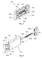
- Figs. 3 and 4 show a first exemplary embodiment of the invention, applied to a vane 120 with a radial grid, obtained for instance by means of two pairs of cavities 127 into which teeth 124A of tips 124 are snap fitted. The tips are thus fixed relative to body 122, whereby vane 120 has a constant length.
- a through bore 101 is formed between both pairs of cavities 127, substantially in a central position, and it forms a seat for an inertial shock-absorber or damper 100.
- "Inertial damper” means a component that, by inertia, tends to oppose the vane movements, in particular to the reversal of the direction of the radial displacement of the vane.
- damper 100 includes a dampening member 102, it too cylindrical, arranged to move along bore 101, and a pair or resilient members 103a, 103b, e.g. a pair of coil springs, opposing the movement of dampening member 102 and arranged at both sides of dampening member 102.
- An end of each spring engages an end portion of dampening member 102, whereas the opposite end abuts against the inner face of tips 124.
- Springs 103a, 103b have substantially the same length so as to keep dampening member 102, in rest conditions, at a substantially central position.
- dampening member 102 has a smaller mass than vane 120. In any case, its mass depends on the vane mass.
- the material of the dampening member can depend on the material of which the vane body is made, but this is not essential.
- inertial damper 100 confers a greater stability to vane 120, thereby solving the problems mentioned above, since it prevents that any loss of contact between tips 124 and the internal wall of the chamber occurs. Thus, possible bounces and the drawbacks related thereto are avoided. It is also to be noted that the action of damper 100 is favoured by the fluid (air, oil, etc.) present in the chamber where vane 120 moves and penetrating into seat 101.
- damper 200 of vane 220 comprises, in place of a central dampening member opposed by two resilient members, a pair of dampening members 202a, 202b located at the ends of seat 201, so that they rest at one end against tips 224, whereas at the other end they are opposed by the single resilient member 203, still shown as a coil spring, arranged between dampening members 202a, 202b.
- the single resilient member 203 still shown as a coil spring, arranged between dampening members 202a, 202b.
- damper 200 is perfectly equivalent to damper 100.
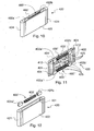
- Figs. 7 to 9 show a second exemplary embodiment of the invention, applied to a vane 320 with an axial grid comprising two sets of blind cavities 325.
- tips 324 are moulded together with body 322 or moulded onto body 322 and are always fixed relative to the body.
- Radial seats for a pair of inertial dampers 300', 300" are formed along the opposite axial edges of body 322. Only one seat 301 is clearly visible in the Figures. Cavities 325 open in the bottom of those seats.
- Each damper 300', 300" is made in similar manner to damper 100 shown in Figs.
- dampening member 302', 302" which, in this example, preferably has the shape of a parallelepiped
- the springs are located at both sides of the respective dampening member 302', 302" and are arranged to keep it, in rest conditions, in a substantially central position in seat 301.
- dampening members 302', 302" are kept in position by undercuts or centring members 304', 304" formed e.g. on the internal surface of tips 324 or in the end walls of seats 301, if the latter are shorter than body 322.
- each damper 400', 400" comprises a pair of dampening members 402a', 402b' and 402a", 402b" having the shape of parallelepipeds, which are located at the ends of respective seats 401 and are opposed by a central spring 403', 403".
- the dampening members are kept in position by undercuts or centring members 404', 404".
- each damper 500', 500" in vane 520 comprises a single dampening member 502', 502", for instance cylindrical, having substantially the same length as the respective seat 501, and an opposing resilient member 503', 503" consisting of a leaf spring, which, for instance, engages cuts 505 in the ends of the respective dampening member 502', 502" and is kept in position by an undercut or a centring member 504', 504" similar to those shown in Figs. 7 to 12 .
- FIG. 15 shows, in a view similar to Fig. 1 , a pump 110 of the kind shown in Fig. 1 and equipped with the vane according to the invention, in particular and by way of example only vane 120 shown in Figs. 3 to 5 .
- the elements of pump 110 other than vane 120 and the components thereof are still denoted by the same reference numerals as in Fig. 1 .
- Both opposing springs of the dampening member are simply denoted 103.
- parallelepiped dampening members can be used in place of the cylindrical dampening members and vice versa.
- the dampening members could also be prismatic with any cross-sectional shape.
- the lightening cavities could be through cavities instead of blind cavities as shown in the drawings.
- a single damper located in a central through bore could be used, like in the embodiment shown in Figs. 3 to 6 .
- the invention can also be applied to multi-vane pumps, as said before.
- the vanes could include a single inertial damper in an axially central position, or a pair of dampers at opposite axial edges.
- the or each damper could include, for instance, a single dampening member and a single opposing member, of which the first is located for instance at the radially internal end of the seat and the second is located for instance at the radially external end of the seat
Landscapes
- Engineering & Computer Science (AREA)
- Mechanical Engineering (AREA)
- General Engineering & Computer Science (AREA)
- Rotary Pumps (AREA)
- Details And Applications Of Rotary Liquid Pumps (AREA)
- Structures Of Non-Positive Displacement Pumps (AREA)
Applications Claiming Priority (1)
| Application Number | Priority Date | Filing Date | Title |
|---|---|---|---|
| IT000997A ITTO20120997A1 (it) | 2012-11-16 | 2012-11-16 | Paletta per rotore di pompa a palette, pompa comprendente la paletta e metodo di pompaggio utilizzante la pompa |
Publications (2)
| Publication Number | Publication Date |
|---|---|
| EP2746582A1 EP2746582A1 (en) | 2014-06-25 |
| EP2746582B1 true EP2746582B1 (en) | 2015-07-01 |
Family
ID=47633399
Family Applications (1)
| Application Number | Title | Priority Date | Filing Date |
|---|---|---|---|
| EP13191325.3A Not-in-force EP2746582B1 (en) | 2012-11-16 | 2013-11-04 | Vane for a rotor of a positive displacement vane pump, pump comprising the vane and pumping method using the pump |
Country Status (2)
| Country | Link |
|---|---|
| EP (1) | EP2746582B1 (it) |
| IT (1) | ITTO20120997A1 (it) |
Families Citing this family (1)
| Publication number | Priority date | Publication date | Assignee | Title |
|---|---|---|---|---|
| MX2018002589A (es) | 2015-08-31 | 2019-01-24 | Siemens Gamesa Renewable Energy Inc | Torre de equipo de concreto con ranura guia de tendon tensado. |
Family Cites Families (5)
| Publication number | Priority date | Publication date | Assignee | Title |
|---|---|---|---|---|
| DE1154316B (de) * | 1961-05-12 | 1963-09-12 | Daimler Benz Ag | Radialdichtung fuer Rotationskolbenmaschinen |
| DE1169739B (de) * | 1962-08-04 | 1964-05-06 | Goetzewerke | Schwingungsgedaempfte Radialdichtung fuer Rotationskolbenmaschinen |
| DE1194210B (de) * | 1963-07-04 | 1965-06-03 | Daimler Benz Ag | Radialdichtung fuer Rotationskolbenmaschinen |
| DE1198149B (de) * | 1963-07-25 | 1965-08-05 | Daimler Benz Ag | Radialdichtung fuer Rotationskolbenmaschinen |
| DE1551147A1 (de) * | 1966-12-16 | 1970-06-11 | Huschang Sabet Dipl Ing | Kraft- oder Arbeitsmaschine mit Dichtungselementen,deren Anpressung an zu dichtende Flaechen der Einwirkung der Fliehkraft unterliegt |
-
2012
- 2012-11-16 IT IT000997A patent/ITTO20120997A1/it unknown
-
2013
- 2013-11-04 EP EP13191325.3A patent/EP2746582B1/en not_active Not-in-force
Also Published As
| Publication number | Publication date |
|---|---|
| ITTO20120997A1 (it) | 2014-05-17 |
| EP2746582A1 (en) | 2014-06-25 |
Similar Documents
| Publication | Publication Date | Title |
|---|---|---|
| EP2789856A2 (en) | Scroll compressor | |
| US20090053088A1 (en) | Reduced Rotor Assembly Diameter Vane Pump | |
| KR101146780B1 (ko) | 베인셀펌프 | |
| EP2613053B1 (en) | Rotary compressor with dual eccentric portion | |
| WO2008070955A1 (en) | A rotary device | |
| JP5585724B2 (ja) | 車両用オイルポンプ | |
| JP6674448B2 (ja) | 偏心駆動ベーンを備えた真空ポンプ(偏心ポンプ設計) | |
| EP1925778A1 (en) | Vane pump | |
| EP2746582B1 (en) | Vane for a rotor of a positive displacement vane pump, pump comprising the vane and pumping method using the pump | |
| RU2382884C2 (ru) | Сферическая объемная роторная машина и способ работы сферической объемной роторной машины | |
| JP7211947B2 (ja) | ポンプシーリング | |
| EP0058456A1 (en) | A rotating vane-pump or -motor | |
| JPS61283780A (ja) | 回転質量体用の偏心駆動装置 | |
| KR20140144287A (ko) | 로터 펌프 및 로터 펌프를 포함하는 회전 기계 | |
| CN205349719U (zh) | 涡旋组件和包括此涡旋组件的涡旋设备 | |
| RU2005102136A (ru) | Ударно-вращательное устройство (варианты) | |
| CN103850929A (zh) | 内接齿轮式泵 | |
| EP3426924B1 (en) | Twin vane rotary vacuum pump | |
| US5692887A (en) | Fixed vane rotary compressor | |
| EP3158196B1 (en) | Rotary fluid pump | |
| EP3172402B1 (en) | Rotary piston and cylinder devices | |
| CN104246130B (zh) | 作为用于流体的泵、压缩机或马达的旋转活塞机 | |
| ITTO20121149A1 (it) | Pompa a palette a cilindrata regolabile e metodo per la regolazione della cilindrata di tale pompa. | |
| CN107076141B (zh) | 油泵 | |
| RU2655092C1 (ru) | Спиральный компрессор |
Legal Events
| Date | Code | Title | Description |
|---|---|---|---|
| PUAI | Public reference made under article 153(3) epc to a published international application that has entered the european phase |
Free format text: ORIGINAL CODE: 0009012 |
|
| 17P | Request for examination filed |
Effective date: 20131104 |
|
| AK | Designated contracting states |
Kind code of ref document: A1 Designated state(s): AL AT BE BG CH CY CZ DE DK EE ES FI FR GB GR HR HU IE IS IT LI LT LU LV MC MK MT NL NO PL PT RO RS SE SI SK SM TR |
|
| AX | Request for extension of the european patent |
Extension state: BA ME |
|
| R17P | Request for examination filed (corrected) |
Effective date: 20141112 |
|
| RBV | Designated contracting states (corrected) |
Designated state(s): AL AT BE BG CH CY CZ DE DK EE ES FI FR GB GR HR HU IE IS IT LI LT LU LV MC MK MT NL NO PL PT RO RS SE SI SK SM TR |
|
| GRAP | Despatch of communication of intention to grant a patent |
Free format text: ORIGINAL CODE: EPIDOSNIGR1 |
|
| INTG | Intention to grant announced |
Effective date: 20150123 |
|
| GRAS | Grant fee paid |
Free format text: ORIGINAL CODE: EPIDOSNIGR3 |
|
| GRAA | (expected) grant |
Free format text: ORIGINAL CODE: 0009210 |
|
| AK | Designated contracting states |
Kind code of ref document: B1 Designated state(s): AL AT BE BG CH CY CZ DE DK EE ES FI FR GB GR HR HU IE IS IT LI LT LU LV MC MK MT NL NO PL PT RO RS SE SI SK SM TR |
|
| REG | Reference to a national code |
Ref country code: GB Ref legal event code: FG4D |
|
| REG | Reference to a national code |
Ref country code: AT Ref legal event code: REF Ref document number: 734126 Country of ref document: AT Kind code of ref document: T Effective date: 20150715 Ref country code: CH Ref legal event code: EP |
|
| REG | Reference to a national code |
Ref country code: IE Ref legal event code: FG4D |
|
| REG | Reference to a national code |
Ref country code: DE Ref legal event code: R096 Ref document number: 602013002129 Country of ref document: DE |
|
| REG | Reference to a national code |
Ref country code: AT Ref legal event code: MK05 Ref document number: 734126 Country of ref document: AT Kind code of ref document: T Effective date: 20150701 |
|
| REG | Reference to a national code |
Ref country code: FR Ref legal event code: PLFP Year of fee payment: 3 |
|
| REG | Reference to a national code |
Ref country code: NL Ref legal event code: MP Effective date: 20150701 |
|
| REG | Reference to a national code |
Ref country code: LT Ref legal event code: MG4D |
|
| PG25 | Lapsed in a contracting state [announced via postgrant information from national office to epo] |
Ref country code: FI Free format text: LAPSE BECAUSE OF FAILURE TO SUBMIT A TRANSLATION OF THE DESCRIPTION OR TO PAY THE FEE WITHIN THE PRESCRIBED TIME-LIMIT Effective date: 20150701 Ref country code: LV Free format text: LAPSE BECAUSE OF FAILURE TO SUBMIT A TRANSLATION OF THE DESCRIPTION OR TO PAY THE FEE WITHIN THE PRESCRIBED TIME-LIMIT Effective date: 20150701 Ref country code: NO Free format text: LAPSE BECAUSE OF FAILURE TO SUBMIT A TRANSLATION OF THE DESCRIPTION OR TO PAY THE FEE WITHIN THE PRESCRIBED TIME-LIMIT Effective date: 20151001 Ref country code: LT Free format text: LAPSE BECAUSE OF FAILURE TO SUBMIT A TRANSLATION OF THE DESCRIPTION OR TO PAY THE FEE WITHIN THE PRESCRIBED TIME-LIMIT Effective date: 20150701 Ref country code: GR Free format text: LAPSE BECAUSE OF FAILURE TO SUBMIT A TRANSLATION OF THE DESCRIPTION OR TO PAY THE FEE WITHIN THE PRESCRIBED TIME-LIMIT Effective date: 20151002 |
|
| PG25 | Lapsed in a contracting state [announced via postgrant information from national office to epo] |
Ref country code: SE Free format text: LAPSE BECAUSE OF FAILURE TO SUBMIT A TRANSLATION OF THE DESCRIPTION OR TO PAY THE FEE WITHIN THE PRESCRIBED TIME-LIMIT Effective date: 20150701 Ref country code: IS Free format text: LAPSE BECAUSE OF FAILURE TO SUBMIT A TRANSLATION OF THE DESCRIPTION OR TO PAY THE FEE WITHIN THE PRESCRIBED TIME-LIMIT Effective date: 20151101 Ref country code: HR Free format text: LAPSE BECAUSE OF FAILURE TO SUBMIT A TRANSLATION OF THE DESCRIPTION OR TO PAY THE FEE WITHIN THE PRESCRIBED TIME-LIMIT Effective date: 20150701 Ref country code: PL Free format text: LAPSE BECAUSE OF FAILURE TO SUBMIT A TRANSLATION OF THE DESCRIPTION OR TO PAY THE FEE WITHIN THE PRESCRIBED TIME-LIMIT Effective date: 20150701 Ref country code: ES Free format text: LAPSE BECAUSE OF FAILURE TO SUBMIT A TRANSLATION OF THE DESCRIPTION OR TO PAY THE FEE WITHIN THE PRESCRIBED TIME-LIMIT Effective date: 20150701 Ref country code: AT Free format text: LAPSE BECAUSE OF FAILURE TO SUBMIT A TRANSLATION OF THE DESCRIPTION OR TO PAY THE FEE WITHIN THE PRESCRIBED TIME-LIMIT Effective date: 20150701 Ref country code: PT Free format text: LAPSE BECAUSE OF FAILURE TO SUBMIT A TRANSLATION OF THE DESCRIPTION OR TO PAY THE FEE WITHIN THE PRESCRIBED TIME-LIMIT Effective date: 20151102 Ref country code: RS Free format text: LAPSE BECAUSE OF FAILURE TO SUBMIT A TRANSLATION OF THE DESCRIPTION OR TO PAY THE FEE WITHIN THE PRESCRIBED TIME-LIMIT Effective date: 20150701 |
|
| REG | Reference to a national code |
Ref country code: DE Ref legal event code: R097 Ref document number: 602013002129 Country of ref document: DE |
|
| PG25 | Lapsed in a contracting state [announced via postgrant information from national office to epo] |
Ref country code: DK Free format text: LAPSE BECAUSE OF FAILURE TO SUBMIT A TRANSLATION OF THE DESCRIPTION OR TO PAY THE FEE WITHIN THE PRESCRIBED TIME-LIMIT Effective date: 20150701 Ref country code: EE Free format text: LAPSE BECAUSE OF FAILURE TO SUBMIT A TRANSLATION OF THE DESCRIPTION OR TO PAY THE FEE WITHIN THE PRESCRIBED TIME-LIMIT Effective date: 20150701 Ref country code: SK Free format text: LAPSE BECAUSE OF FAILURE TO SUBMIT A TRANSLATION OF THE DESCRIPTION OR TO PAY THE FEE WITHIN THE PRESCRIBED TIME-LIMIT Effective date: 20150701 Ref country code: CZ Free format text: LAPSE BECAUSE OF FAILURE TO SUBMIT A TRANSLATION OF THE DESCRIPTION OR TO PAY THE FEE WITHIN THE PRESCRIBED TIME-LIMIT Effective date: 20150701 |
|
| PLBE | No opposition filed within time limit |
Free format text: ORIGINAL CODE: 0009261 |
|
| STAA | Information on the status of an ep patent application or granted ep patent |
Free format text: STATUS: NO OPPOSITION FILED WITHIN TIME LIMIT |
|
| PG25 | Lapsed in a contracting state [announced via postgrant information from national office to epo] |
Ref country code: RO Free format text: LAPSE BECAUSE OF FAILURE TO SUBMIT A TRANSLATION OF THE DESCRIPTION OR TO PAY THE FEE WITHIN THE PRESCRIBED TIME-LIMIT Effective date: 20150701 |
|
| 26N | No opposition filed |
Effective date: 20160404 |
|
| PG25 | Lapsed in a contracting state [announced via postgrant information from national office to epo] |
Ref country code: MC Free format text: LAPSE BECAUSE OF FAILURE TO SUBMIT A TRANSLATION OF THE DESCRIPTION OR TO PAY THE FEE WITHIN THE PRESCRIBED TIME-LIMIT Effective date: 20150701 Ref country code: LU Free format text: LAPSE BECAUSE OF FAILURE TO SUBMIT A TRANSLATION OF THE DESCRIPTION OR TO PAY THE FEE WITHIN THE PRESCRIBED TIME-LIMIT Effective date: 20151104 |
|
| REG | Reference to a national code |
Ref country code: IE Ref legal event code: MM4A |
|
| PG25 | Lapsed in a contracting state [announced via postgrant information from national office to epo] |
Ref country code: SI Free format text: LAPSE BECAUSE OF FAILURE TO SUBMIT A TRANSLATION OF THE DESCRIPTION OR TO PAY THE FEE WITHIN THE PRESCRIBED TIME-LIMIT Effective date: 20150701 |
|
| PG25 | Lapsed in a contracting state [announced via postgrant information from national office to epo] |
Ref country code: IE Free format text: LAPSE BECAUSE OF NON-PAYMENT OF DUE FEES Effective date: 20151104 |
|
| REG | Reference to a national code |
Ref country code: FR Ref legal event code: PLFP Year of fee payment: 4 |
|
| PG25 | Lapsed in a contracting state [announced via postgrant information from national office to epo] |
Ref country code: BE Free format text: LAPSE BECAUSE OF FAILURE TO SUBMIT A TRANSLATION OF THE DESCRIPTION OR TO PAY THE FEE WITHIN THE PRESCRIBED TIME-LIMIT Effective date: 20150701 |
|
| PG25 | Lapsed in a contracting state [announced via postgrant information from national office to epo] |
Ref country code: BG Free format text: LAPSE BECAUSE OF FAILURE TO SUBMIT A TRANSLATION OF THE DESCRIPTION OR TO PAY THE FEE WITHIN THE PRESCRIBED TIME-LIMIT Effective date: 20150701 Ref country code: HU Free format text: LAPSE BECAUSE OF FAILURE TO SUBMIT A TRANSLATION OF THE DESCRIPTION OR TO PAY THE FEE WITHIN THE PRESCRIBED TIME-LIMIT; INVALID AB INITIO Effective date: 20131104 |
|
| PG25 | Lapsed in a contracting state [announced via postgrant information from national office to epo] |
Ref country code: CY Free format text: LAPSE BECAUSE OF FAILURE TO SUBMIT A TRANSLATION OF THE DESCRIPTION OR TO PAY THE FEE WITHIN THE PRESCRIBED TIME-LIMIT Effective date: 20150701 Ref country code: NL Free format text: LAPSE BECAUSE OF FAILURE TO SUBMIT A TRANSLATION OF THE DESCRIPTION OR TO PAY THE FEE WITHIN THE PRESCRIBED TIME-LIMIT Effective date: 20150701 |
|
| REG | Reference to a national code |
Ref country code: CH Ref legal event code: PL |
|
| PG25 | Lapsed in a contracting state [announced via postgrant information from national office to epo] |
Ref country code: CH Free format text: LAPSE BECAUSE OF NON-PAYMENT OF DUE FEES Effective date: 20161130 Ref country code: LI Free format text: LAPSE BECAUSE OF NON-PAYMENT OF DUE FEES Effective date: 20161130 |
|
| PG25 | Lapsed in a contracting state [announced via postgrant information from national office to epo] |
Ref country code: MT Free format text: LAPSE BECAUSE OF FAILURE TO SUBMIT A TRANSLATION OF THE DESCRIPTION OR TO PAY THE FEE WITHIN THE PRESCRIBED TIME-LIMIT Effective date: 20150701 |
|
| REG | Reference to a national code |
Ref country code: FR Ref legal event code: PLFP Year of fee payment: 5 |
|
| PG25 | Lapsed in a contracting state [announced via postgrant information from national office to epo] |
Ref country code: SM Free format text: LAPSE BECAUSE OF FAILURE TO SUBMIT A TRANSLATION OF THE DESCRIPTION OR TO PAY THE FEE WITHIN THE PRESCRIBED TIME-LIMIT Effective date: 20150701 |
|
| PG25 | Lapsed in a contracting state [announced via postgrant information from national office to epo] |
Ref country code: MK Free format text: LAPSE BECAUSE OF FAILURE TO SUBMIT A TRANSLATION OF THE DESCRIPTION OR TO PAY THE FEE WITHIN THE PRESCRIBED TIME-LIMIT Effective date: 20150701 |
|
| PG25 | Lapsed in a contracting state [announced via postgrant information from national office to epo] |
Ref country code: AL Free format text: LAPSE BECAUSE OF FAILURE TO SUBMIT A TRANSLATION OF THE DESCRIPTION OR TO PAY THE FEE WITHIN THE PRESCRIBED TIME-LIMIT Effective date: 20150701 Ref country code: TR Free format text: LAPSE BECAUSE OF FAILURE TO SUBMIT A TRANSLATION OF THE DESCRIPTION OR TO PAY THE FEE WITHIN THE PRESCRIBED TIME-LIMIT Effective date: 20150701 |
|
| PGFP | Annual fee paid to national office [announced via postgrant information from national office to epo] |
Ref country code: FR Payment date: 20191121 Year of fee payment: 7 |
|
| PGFP | Annual fee paid to national office [announced via postgrant information from national office to epo] |
Ref country code: DE Payment date: 20200124 Year of fee payment: 7 Ref country code: GB Payment date: 20191126 Year of fee payment: 7 |
|
| REG | Reference to a national code |
Ref country code: DE Ref legal event code: R119 Ref document number: 602013002129 Country of ref document: DE |
|
| GBPC | Gb: european patent ceased through non-payment of renewal fee |
Effective date: 20201104 |
|
| PG25 | Lapsed in a contracting state [announced via postgrant information from national office to epo] |
Ref country code: FR Free format text: LAPSE BECAUSE OF NON-PAYMENT OF DUE FEES Effective date: 20201130 |
|
| PG25 | Lapsed in a contracting state [announced via postgrant information from national office to epo] |
Ref country code: DE Free format text: LAPSE BECAUSE OF NON-PAYMENT OF DUE FEES Effective date: 20210601 Ref country code: GB Free format text: LAPSE BECAUSE OF NON-PAYMENT OF DUE FEES Effective date: 20201104 |
|
| PGFP | Annual fee paid to national office [announced via postgrant information from national office to epo] |
Ref country code: IT Payment date: 20211130 Year of fee payment: 9 |
|
| PG25 | Lapsed in a contracting state [announced via postgrant information from national office to epo] |
Ref country code: IT Free format text: LAPSE BECAUSE OF NON-PAYMENT OF DUE FEES Effective date: 20221104 |