EP2746583A1 - Fluegelpumpe - Google Patents
Fluegelpumpe Download PDFInfo
- Publication number
- EP2746583A1 EP2746583A1 EP13197348.9A EP13197348A EP2746583A1 EP 2746583 A1 EP2746583 A1 EP 2746583A1 EP 13197348 A EP13197348 A EP 13197348A EP 2746583 A1 EP2746583 A1 EP 2746583A1
- Authority
- EP
- European Patent Office
- Prior art keywords
- intermediate plate
- housing
- cover member
- oil
- side plate
- Prior art date
- Legal status (The legal status is an assumption and is not a legal conclusion. Google has not performed a legal analysis and makes no representation as to the accuracy of the status listed.)
- Withdrawn
Links
- 239000012530 fluid Substances 0.000 claims abstract description 13
- 230000004308 accommodation Effects 0.000 claims description 15
- 230000002093 peripheral effect Effects 0.000 claims description 15
- 238000000034 method Methods 0.000 description 14
- 230000008569 process Effects 0.000 description 14
- 230000005540 biological transmission Effects 0.000 description 4
- 238000007906 compression Methods 0.000 description 3
- 238000003754 machining Methods 0.000 description 2
- 238000004519 manufacturing process Methods 0.000 description 2
- 230000008859 change Effects 0.000 description 1
- 238000005520 cutting process Methods 0.000 description 1
- 238000007599 discharging Methods 0.000 description 1
- 230000003628 erosive effect Effects 0.000 description 1
- 238000005192 partition Methods 0.000 description 1
- 238000004080 punching Methods 0.000 description 1
- 230000009467 reduction Effects 0.000 description 1
- 230000004044 response Effects 0.000 description 1
Images

Classifications
-
- F—MECHANICAL ENGINEERING; LIGHTING; HEATING; WEAPONS; BLASTING
- F04—POSITIVE - DISPLACEMENT MACHINES FOR LIQUIDS; PUMPS FOR LIQUIDS OR ELASTIC FLUIDS
- F04C—ROTARY-PISTON, OR OSCILLATING-PISTON, POSITIVE-DISPLACEMENT MACHINES FOR LIQUIDS; ROTARY-PISTON, OR OSCILLATING-PISTON, POSITIVE-DISPLACEMENT PUMPS
- F04C2/00—Rotary-piston machines or pumps
- F04C2/30—Rotary-piston machines or pumps having the characteristics covered by two or more groups F04C2/02, F04C2/08, F04C2/22, F04C2/24 or having the characteristics covered by one of these groups together with some other type of movement between co-operating members
- F04C2/34—Rotary-piston machines or pumps having the characteristics covered by two or more groups F04C2/02, F04C2/08, F04C2/22, F04C2/24 or having the characteristics covered by one of these groups together with some other type of movement between co-operating members having the movement defined in groups F04C2/08 or F04C2/22 and relative reciprocation between the co-operating members
- F04C2/344—Rotary-piston machines or pumps having the characteristics covered by two or more groups F04C2/02, F04C2/08, F04C2/22, F04C2/24 or having the characteristics covered by one of these groups together with some other type of movement between co-operating members having the movement defined in groups F04C2/08 or F04C2/22 and relative reciprocation between the co-operating members with vanes reciprocating with respect to the inner member
-
- F—MECHANICAL ENGINEERING; LIGHTING; HEATING; WEAPONS; BLASTING
- F04—POSITIVE - DISPLACEMENT MACHINES FOR LIQUIDS; PUMPS FOR LIQUIDS OR ELASTIC FLUIDS
- F04C—ROTARY-PISTON, OR OSCILLATING-PISTON, POSITIVE-DISPLACEMENT MACHINES FOR LIQUIDS; ROTARY-PISTON, OR OSCILLATING-PISTON, POSITIVE-DISPLACEMENT PUMPS
- F04C15/00—Component parts, details or accessories of machines, pumps or pumping installations, not provided for in groups F04C2/00 - F04C14/00
- F04C15/0003—Sealing arrangements in rotary-piston machines or pumps
- F04C15/0023—Axial sealings for working fluid
-
- F—MECHANICAL ENGINEERING; LIGHTING; HEATING; WEAPONS; BLASTING
- F04—POSITIVE - DISPLACEMENT MACHINES FOR LIQUIDS; PUMPS FOR LIQUIDS OR ELASTIC FLUIDS
- F04C—ROTARY-PISTON, OR OSCILLATING-PISTON, POSITIVE-DISPLACEMENT MACHINES FOR LIQUIDS; ROTARY-PISTON, OR OSCILLATING-PISTON, POSITIVE-DISPLACEMENT PUMPS
- F04C2/00—Rotary-piston machines or pumps
- F04C2/30—Rotary-piston machines or pumps having the characteristics covered by two or more groups F04C2/02, F04C2/08, F04C2/22, F04C2/24 or having the characteristics covered by one of these groups together with some other type of movement between co-operating members
- F04C2/34—Rotary-piston machines or pumps having the characteristics covered by two or more groups F04C2/02, F04C2/08, F04C2/22, F04C2/24 or having the characteristics covered by one of these groups together with some other type of movement between co-operating members having the movement defined in groups F04C2/08 or F04C2/22 and relative reciprocation between the co-operating members
- F04C2/344—Rotary-piston machines or pumps having the characteristics covered by two or more groups F04C2/02, F04C2/08, F04C2/22, F04C2/24 or having the characteristics covered by one of these groups together with some other type of movement between co-operating members having the movement defined in groups F04C2/08 or F04C2/22 and relative reciprocation between the co-operating members with vanes reciprocating with respect to the inner member
- F04C2/3441—Rotary-piston machines or pumps having the characteristics covered by two or more groups F04C2/02, F04C2/08, F04C2/22, F04C2/24 or having the characteristics covered by one of these groups together with some other type of movement between co-operating members having the movement defined in groups F04C2/08 or F04C2/22 and relative reciprocation between the co-operating members with vanes reciprocating with respect to the inner member the inner and outer member being in contact along one line or continuous surface substantially parallel to the axis of rotation
-
- F—MECHANICAL ENGINEERING; LIGHTING; HEATING; WEAPONS; BLASTING
- F04—POSITIVE - DISPLACEMENT MACHINES FOR LIQUIDS; PUMPS FOR LIQUIDS OR ELASTIC FLUIDS
- F04C—ROTARY-PISTON, OR OSCILLATING-PISTON, POSITIVE-DISPLACEMENT MACHINES FOR LIQUIDS; ROTARY-PISTON, OR OSCILLATING-PISTON, POSITIVE-DISPLACEMENT PUMPS
- F04C2250/00—Geometry
- F04C2250/10—Geometry of the inlet or outlet
- F04C2250/101—Geometry of the inlet or outlet of the inlet
-
- F—MECHANICAL ENGINEERING; LIGHTING; HEATING; WEAPONS; BLASTING
- F04—POSITIVE - DISPLACEMENT MACHINES FOR LIQUIDS; PUMPS FOR LIQUIDS OR ELASTIC FLUIDS
- F04C—ROTARY-PISTON, OR OSCILLATING-PISTON, POSITIVE-DISPLACEMENT MACHINES FOR LIQUIDS; ROTARY-PISTON, OR OSCILLATING-PISTON, POSITIVE-DISPLACEMENT PUMPS
- F04C2270/00—Control; Monitoring or safety arrangements
- F04C2270/42—Conditions at the inlet of a pump or machine
Definitions
- the invention relates to a vane pump that pressurizes and supplies a fluid.
- a vane pump is used as a hydraulic pressure supply source that supplies a fluid such as oil to hydraulic equipment.
- a configuration is known in which the vane pump is mounted on a vehicle as an oil pump that supplies pressurized oil to a transmission or a power steering system of the vehicle.
- a rotary driving force of an engine or the like is input to a rotor, whereby a pump operation is performed. Therefore, depending on the traveling condition of the vehicle, the number of revolutions of the rotor becomes high due to an increase in the number of revolutions of the engine. Then, a large amount of oil is sucked from an intake port into a pump chamber, whereby hydraulic pressure in the intake port is lowered and a cavitation may be caused in an opening portion of the intake port or the pump chamber.
- JP 06-280754 A describes a configuration in which a back flow of centrifugal hydraulic pressure from a pump chamber to an intake port is prevented by appropriately setting the radial width of an opening portion of the intake port with respect to the pump chamber.
- JP 2006-266106 A describes a configuration in which when hydraulic pressure of a discharge port becomes greater than or equal to a certain value, a part of the pressurized oil is returned to an intake port. With this configuration, the hydraulic pressure of the intake port is prevented from becoming excessively low pressure, whereby occurrence of a cavitation is suppressed.
- An object of the invention is to provide a vane pump in which occurrence of a cavitation can be suppressed with the use of a configuration different from a configuration in related art.
- a vane pump including: a housing; a cam ring that is provided inside the housing and has a cam face in an inner peripheral surface of the cam ring; a rotor that is rotatably provided on an inner periphery side of the cam ring and has a plurality of accommodation grooves extending radially inward from an outer peripheral surface of the rotor; a plurality of vanes that is slidably accommodated in the respective accommodation grooves and circumferentially divides a space between the cam face and the outer peripheral surface of the rotor to form a plurality of pump chambers; a side plate that is axially adjacent to the cam ring and the rotor and constitutes a portion of an intake port that is opened so as to allow a fluid to be sucked into the pump chambers; an intermediate plate axially adjacent to the housing and the side plate; and a cover member that is fixed to an axial end portion of the housing in a manner such that the intermediate plate is interposed between
- a vane pump 1 according to an embodiment will be described with reference to the drawings.
- a configuration is exemplified in which oil is used as a fluid and the vane pump 1 is applied as a supply source that supplies hydraulic pressure used for a clutch control for a transmission of a vehicle.
- the vane pump 1 is operated when the rotary driving force of an engine or the like of the vehicle is input to a drive shaft 90, and the vane pump 1 discharges oil at a flow rate according to the number of revolutions of the engine.
- the vane pump 1 may have a configuration in which a flow rate control valve (not shown) is provided so as to control the discharge flow rate proportional to the number of revolutions of the drive shaft 90 to a predetermined flow rate necessary for hydraulic equipment.
- a transmission-side (right side of FIG. 1 ) in the vane pump 1 is regarded as a front side
- a side (left side of FIG. 1 ) in the vane pump 1, which is opposite to the transmission is regarded as a rear side.
- the vane pump 1 is configured to include a housing 10, a cam ring 20, a rotor 30, a plurality of vanes 40, a front side plate 50, a rear side plate 60, an intermediate plate 70, and a cover member 80, as shown in FIG. 1 .
- the housing 10 has an accommodation portion 11 having a tubular shape and is opened at a fitting end face 12 on the rear side. Further, in the fitting end face 12, a groove 12a is formed at a phase different from that in FIG. 1 .
- the groove 12a of the housing 10 and the surface of the intermediate plate 70 adjacent to the fitting end face 12 constitute a portion of a flow passage Ts for oil.
- the housing 10 supports the drive shaft 90 through a bearing 13 so that the drive shaft 90 is rotatable.
- the drive shaft 90 is a shaft member to which a rotary driving force is input by the engine through a belt.
- a first intake oil passage Ti1 is formed in the housing 10.
- the first intake oil passage Ti1 is formed in a tubular shape, and oil introduced from the outside into the housing 10 flows to the inner portion of the housing 10 through the first intake oil passage Ti1.
- the first intake oil passage Ti1 is opened in the inner peripheral surface of the accommodation portion 11.
- the entire cam ring 20 is formed in an annular shape.
- the cam ring 20 is provided in the inner portion (the accommodation portion 11) of the housing 10.
- the cam ring 20 is accommodated in the accommodation portion 11 of the housing 10 in a state in which the cam ring 20 is sandwiched between the front side plate 50 and the rear side plate 60 from both sides in an axial direction. Relative rotation of the cam ring 20 with respect to the housing 10 is restricted by pins (not shown).
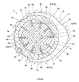
- a cam face 21 is formed in the inner peripheral surface of the cam ring 20, as shown in FIG. 2 .
- the cam face 21 has a substantially elliptical shape, and varies at intervals of 180 degrees.
- the clearance is a flow passage in which oil that has passed through the first intake oil passage Ti1 can flow in a circumferential direction on the outer periphery side of the cam ring 20.
- the clearance forms a second intake oil passage Ti2 in the vane pump 1. That is, the second intake oil passage Ti2 is constituted by the inner peripheral surface of the accommodation portion 11 of the housing 10 and the outer peripheral surface of the cam ring 20.
- the rotor 30 is disposed on the inner periphery side of the cam ring 20 and spline-fitted to the drive shaft 90. Thus, the rotor 30 rotates together with the drive shaft 90 and is rotatable with respect to the cam ring 20. Further, a plurality of accommodation grooves 31 extending radially inward from the outer periphery surface is formed in the rotor 30.
- the accommodation grooves 31 are radial slits formed at regular intervals (in this embodiment, at ten locations) in the circumferential direction, as shown in FIG. 2 .
- Each of the vanes 40 is formed in a plate shape and accommodated in a corresponding one of the accommodation grooves 31 in the rotor 30 so as to be able to slide in the radial direction of the rotor 30.
- a distal end portion of each of the vanes 40 is always brought into contact with the cam face 21 of the cam ring 20 by the hydraulic pressure of oil introduced into the inner portion of the rotor 30, a centrifugal force, a spring force, or the like.
- the vanes 40 circumferentially divide a space between the cam face 21 and the outer peripheral surface of the rotor 30 to form a plurality of pump chambers Cp.
- each of the pump chambers Cp is defined in the axial direction by the rear-side end face of the front side plate 50 and the front-side end face of the rear side plate 60.
- the rotor 30 is sandwiched by the rear-side end face of the front side plate 50 and the front-side end face of the rear side plate 60 from both sides in the axial direction. Therefore, each of the pump chambers Cp is configured so that the volume of the pump chamber Cp expands and contracts depending on a change in the distance between the cam face 21 and the outer peripheral surface of the rotor 30, with the rotation of the rotor 30.
- each of the pump chambers Cp repeatedly performs an intake process of sucking oil with an increase in the volume, a compression process of compressing the sucked oil, and a discharge process of discharging the oil with a reduction in the volume.
- the front side plate 50 is disposed adjacent to the front side of the cam ring 20 and fixed to a bottom portion of the accommodation portion 11 in the housing 10 through a seal member, as shown in FIG. 1 .
- a pair of recessed grooves 51 is formed in the rear-side end face of the front side plate 50.
- the recessed grooves 51 extend radially outward from positions corresponding to the angular ranges of two locations where the respective pump chambers Cp in the intake process are located.
- the recessed grooves 51 of the front side plate 50 are formed such that a groove width increases toward the radially outside.
- the recessed grooves 51 with the above-described configuration, and the front-side end face of the cam ring 20 constitute a pair of first intake ports Pi1 which is opened to the respective pump chambers Cp in the intake process and through which oil is supplied to the respective pump chambers Cp.
- the first intake ports Pi1 communicate with the second intake oil passage Ti2, and thus, oil is supplied to the first intake ports Pi1.
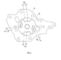
- the rear side plate 60 is axially adjacent to the rear sides of the cam ring 20 and the rotor 30 and is positioned with respect to the housing 10 by pins (not shown). Then, the cover member 80 (described later) is fixed to the housing 10, whereby the rear side plate 60 is fixed with respect to the housing 10 through the intermediate plate 70. Further, a pair of cutout portions 61 is formed in the rear side plate 60, as shown in FIG. 3 . Each of the cutout portions 61 is formed by cutting out a portion of an outer peripheral edge of the rear side plate 60 toward the radially inside. Each of the cutout portions 61 is formed such that a circumferential width increases toward the radially outside.
- the cutout portions 61 of the rear side plate 60, which have the above-described configuration, and the rear-side end face of the cam ring 20 constitute a pair of second intake ports Pi2 which is opened to the respective pump chambers Cp in the intake process and through which oil is supplied to the respective pump chambers Cp.
- the second intake ports Pi2 are located on the opposite side in the axial direction to the first intake ports Pi1 with the pump chambers Cp interposed therebetween.
- the second intake ports Pi2 communicate with the second intake oil passage Ti2, and thus, oil is supplied to the second intake ports Pi2.
- a pair of through-holes 62 axially extending through the rear side plate 60 is formed between the cutout portions 61 in the circumferential direction.
- the through-holes 62 are respectively disposed so as to correspond to the angular ranges of two locations where the respective pump chambers Cp in the discharge process among the pump chambers Cp are located, and the through-holes 62 are opened to the respective pump chambers Cp in the discharge process.
- the through-holes 62 constitute a pair of discharge ports Px through which oil is discharged from the respective pump chambers Cp in the discharge process.
- the intermediate plate 70 is disposed adjacent to the rear sides of the housing 10 and the rear side plate 60 and interposed between the housing 10 and the cover member 80, as shown in FIG. 1 .
- through-holes 71 are respectively formed at positions corresponding to the cutout portions 61 of the rear side plate 60.
- the shape of the section of the through-hole 71 orthogonal to the axis is substantially the same as the shape of the section of the cutout portion 61 orthogonal to the axis.
- discharge holes 72 are respectively formed at positions corresponding to the discharge ports Px (the through-holes 62) of the rear side plate 60.
- Each of the discharge holes 72 communicates with the corresponding through-hole 62.
- Each of the discharge holes 72 and the corresponding through-hole 62 constitute a discharge port Px.
- the intermediate plate 70 sealability is secured at sites where the intermediate plate 70 comes into surface contact with the fitting end face 12 of the housing 10 and the front-side end face of the cover member 80.
- the intermediate plate 70 also functions as a partition plate that separates the low-pressure side (the housing 10-side) where oil is led into the vane pump 1, from the high-pressure side (the cover member 80-side) where oil is led out from the vane pump 1 to the outside.
- a portion of the flow passage Ts for oil is constituted by the groove 12a of the fitting end face 12 and a portion of the surface of the intermediate plate 70, the surface being adjacent to the fitting end face 12 of the housing 10.
- the vane pump 1 according to this embodiment is different from a configuration in which a rear side plate is formed integrally with a cover member, as in related art.
- a portion of the flow passage Ts and the like are configured in the intermediate plate 70.
- the cover member 80 is fixed to the fitting end face 12 that is an axial end portion of the housing 10 in a manner such that the intermediate plate 70 is interposed between the cover member 80 and the housing 10, as shown in FIG. 1 .
- the cover member 80 is positioned with respect to the housing 10 by a plurality of pins 81 and fixed by connection members such as bolts inserted through holes formed in the intermediate plate 70.
- connection members such as bolts inserted through holes formed in the intermediate plate 70.
- the cover member 80 and the intermediate plate 70 close an opening portion of the accommodation portion 11 in the housing 10.
- the cover member 80 supports an end portion of the drive shaft 90 through a bearing 82 so that the drive shaft 90 is rotatable, by a bearing portion having a cylindrical inner peripheral surface concentric with the drive shaft 90.
- recessed portions 83 are respectively formed to extend toward the rear side from the front-side end face at positions corresponding to the through-holes 71 of the intermediate plate 70.
- Each of the recessed portions 83 is formed such that the shape of the section of the recessed portion 83 orthogonal to the axis is substantially the same as that of the through-hole 71 of the intermediate plate 70.
- Each of the recessed portions 83 communicates with the cutout portion 61 of the rear side plate 60 through the through-hole 71.
- each of the second intake ports Pi2 is constituted by the through-hole 71 of the intermediate plate 70, the recessed portion 83 of the cover member 80, and the cutout portion 61 of the rear side plate 60.
- the second intake ports Pi2 which communicate with the second intake oil passage Ti2 and are opened to the pump chambers Cp in the intake process, are constituted by the cutout portions 61 of the rear side plate 60, the rear-side end face of the cam ring 20, the through-holes 71 of the intermediate plate 70, and the recessed portions 83 of the cover member 80.
- discharge passages (not shown) communicating with the discharge holes 72 of the intermediate plate 70 are respectively formed at positions corresponding to the discharge holes 72. Oil whose pressure has become high in the discharge ports Px is led to the outside of the vane pump 1 through the discharge passages.
- a flow rate control valve may be provided, for example, between the discharge passage and the second intake port Pi2. The flow rate control valve is provided for returning a part of oil discharged into the discharge passage, to the intake side through a bypass passage, and controlling the flow rate of oil delivered to hydraulic equipment to a certain flow rate.
- the volumes of the pump chambers Cp are gradually reduced with the rotation of the rotor 30 so that the sucked oil is compressed.
- oil is discharged from the opening portions of the discharge ports Px constituted by the through-holes 62 of the rear side plate 60 and the discharge holes 72 of the intermediate plate 70. Then, pressurized oil is led out from the vane pump 1 to the transmission outside the vane pump 1 by way of the discharge passages of the cover member 80.
- the oil supplied to the second intake ports Pi2 also flows into and is filled in the through-holes 71 of the intermediate plate 70 and the recessed portions 83 of the cover member 80. Then, the amount of oil according to the number of revolutions of the rotor 30 is supplied from the opening portions of the intake ports Pi1 and Pi2 facing each other in the axial direction, into the pump chambers Cp in the intake process.
- the intake ports Pi1 and Pi2 increase the maximum supply amount of oil that can be supplied to the pump chambers Cp in the intake process at one time, as a whole, and thus suppress shortage of oil when the rotor 30 is rotated at a high speed.
- an excessive drop in hydraulic pressure in the intake ports Pi1 and Pi2 is prevented.
- the second intake ports Pi2 are constituted by the respective cutout portions 61 of the rear side plate 60, the respective through-holes 71 of the intermediate plate 70, and the respective recessed portions 83 of the cover member 80.
- an intake port is constituted by the cutout portion 61 and the surface on the front side of the intermediate plate 70
- the intermediate plate 70 and the groove 12a of the fitting end face 12 of the housing 10 constitute a portion of the flow passage Ts through which oil flows.
- the degree of freedom of design of the flow passage Ts can be improved by constituting the flow passage Ts while securing sealability, with the use of different members (the housing 10 and the intermediate plate 70) in this manner.
- each of the second intake ports Pi2 is constituted by the through-hole 71 of the intermediate plate 70 and the recessed portion 83 of the cover member 80.
- each of the second intake ports Pi2 is constituted by the through-hole 71 of the intermediate plate 70 and the recessed portion 83 of the cover member 80.
- each of the second intake ports Pi2 may be constituted by the through-hole 71 of the intermediate plate 70 and the front-side end face of the cover member 80.
- the volume of each of the second intake ports Pi2 is increased depending on the sectional area of the through-hole 71 and the thickness of the intermediate plate 70.
- the amount of increase in the volume of each of the second intake ports Pi2 is reduced, as compared to the configuration exemplified in this embodiment.
- the recessed portions 83 are not formed in the cover member 80, it is possible to reduce machining cost, and it is also possible to easily suppress occurrence of a cavitation by only machining the intermediate plate 70.
- the through-holes 71 can be formed in the intermediate plate 70, for example, by punching at the same time as the time when other holes, i.e., discharge holes 72 and pin holes are formed. Therefore, it is possible to suppress the manufacturing cost, as in the embodiment.
- each of the second intake ports Pi2 may be formed by a recessed portion formed to be shallower than the thickness of the intermediate plate 70.
- the recessed portion does not have an influence on the cover member 80-side. Accordingly, it is possible to increase the effective sectional area of each of the second intake ports Pi2 by the recessed portion while the intermediate plate 70 maintains sealability with respect to the cover member 80.
- each of the recessed portions of the intermediate plate 70 can be appropriately set, it is possible to rectify the flow of oil by setting the shape of the recessed portion in accordance with a supply path for oil from the second intake oil passage Ti2 to the second intake port Pi2.
- oil is used as the fluid and the vane pump 1 is used as a hydraulic pressure supply source that supplies oil to hydraulic equipment.
- the invention may be applied to a vane pump for a fluid other than oil, if the vane pump can discharge the fluid introduced by a pump operation.
- the intermediate plate 70 and the groove 12a of the fitting end face 12 in the housing 10 constitute a portion of the flow passage Ts for oil.
- the invention may be applied to the vane pump. Accordingly, for example, the intermediate plate 70 and a groove or a hole formed in the end face of the rear side plate 60 or the cover member 80 adjacent to the intermediate plate 70 may similarly constitute the flow passage for oil, the intake port, or the like.
- a vane pump includes a housing, a cam ring, a rotor, a plurality of vanes that forms a plurality of pump chambers, a side plate constituting a portion of an intake port, an intermediate plate axially adjacent to the housing and the side plate, and a cover member.
- a portion of a flow passage, through which a fluid flows, is constituted by a surface of the intermediate plate and at least one of the housing, the side plate, and the cover member, the surface of the intermediate plate being adjacent to the at least one of the housing, the side plate, and the cover member.
- a through-hole or a recessed portion is formed in the intermediate plate, and the through-hole or the recessed portion of the intermediate plate and the side plate constitute a portion of the intake port.
Landscapes
- Engineering & Computer Science (AREA)
- Mechanical Engineering (AREA)
- General Engineering & Computer Science (AREA)
- Rotary Pumps (AREA)
- Details And Applications Of Rotary Liquid Pumps (AREA)
Applications Claiming Priority (1)
| Application Number | Priority Date | Filing Date | Title |
|---|---|---|---|
| JP2012277656A JP2014122558A (ja) | 2012-12-20 | 2012-12-20 | ベーンポンプ |
Publications (1)
| Publication Number | Publication Date |
|---|---|
| EP2746583A1 true EP2746583A1 (de) | 2014-06-25 |
Family
ID=49911181
Family Applications (1)
| Application Number | Title | Priority Date | Filing Date |
|---|---|---|---|
| EP13197348.9A Withdrawn EP2746583A1 (de) | 2012-12-20 | 2013-12-16 | Fluegelpumpe |
Country Status (4)
| Country | Link |
|---|---|
| US (1) | US20140178239A1 (de) |
| EP (1) | EP2746583A1 (de) |
| JP (1) | JP2014122558A (de) |
| CN (1) | CN103883519A (de) |
Families Citing this family (5)
| Publication number | Priority date | Publication date | Assignee | Title |
|---|---|---|---|---|
| KR101740610B1 (ko) * | 2015-06-11 | 2017-06-08 | 명화공업주식회사 | 베인펌프 |
| JP2017078366A (ja) * | 2015-10-21 | 2017-04-27 | Kyb株式会社 | ベーンポンプ |
| TR201617408A2 (tr) * | 2016-11-29 | 2017-01-23 | Hema Enduestri Anonim Sirketi | Emi̇ş performansi arttirilmiş bi̇r deği̇şken deplasmanli paletli̇ pompa |
| DE112019005598B4 (de) | 2018-11-09 | 2025-04-24 | Kyb Corporation | Elektrische Ölpumpe |
| US11333254B2 (en) * | 2018-12-07 | 2022-05-17 | Tescom Corporation | Control valves |
Citations (6)
| Publication number | Priority date | Publication date | Assignee | Title |
|---|---|---|---|---|
| US2538194A (en) * | 1944-05-25 | 1951-01-16 | Oilgear Co | Hydrodynamic machine |
| US4008002A (en) * | 1975-11-07 | 1977-02-15 | Sperry Rand Corporation | Vane pump with speed responsive check plate deflection |
| JPH06280754A (ja) | 1993-03-31 | 1994-10-04 | Nissan Motor Co Ltd | ベーンポンプ |
| JPH11351159A (ja) * | 1998-06-10 | 1999-12-21 | Showa Corp | ベーンポンプ |
| JP2004232465A (ja) * | 2003-01-28 | 2004-08-19 | Hitachi Unisia Automotive Ltd | 双方向形のベーンポンプ及びベーンモータ |
| JP2006266106A (ja) | 2005-03-22 | 2006-10-05 | Jtekt Corp | オイルポンプ |
-
2012
- 2012-12-20 JP JP2012277656A patent/JP2014122558A/ja active Pending
-
2013
- 2013-12-13 US US14/105,570 patent/US20140178239A1/en not_active Abandoned
- 2013-12-16 EP EP13197348.9A patent/EP2746583A1/de not_active Withdrawn
- 2013-12-18 CN CN201310698063.4A patent/CN103883519A/zh active Pending
Patent Citations (6)
| Publication number | Priority date | Publication date | Assignee | Title |
|---|---|---|---|---|
| US2538194A (en) * | 1944-05-25 | 1951-01-16 | Oilgear Co | Hydrodynamic machine |
| US4008002A (en) * | 1975-11-07 | 1977-02-15 | Sperry Rand Corporation | Vane pump with speed responsive check plate deflection |
| JPH06280754A (ja) | 1993-03-31 | 1994-10-04 | Nissan Motor Co Ltd | ベーンポンプ |
| JPH11351159A (ja) * | 1998-06-10 | 1999-12-21 | Showa Corp | ベーンポンプ |
| JP2004232465A (ja) * | 2003-01-28 | 2004-08-19 | Hitachi Unisia Automotive Ltd | 双方向形のベーンポンプ及びベーンモータ |
| JP2006266106A (ja) | 2005-03-22 | 2006-10-05 | Jtekt Corp | オイルポンプ |
Also Published As
| Publication number | Publication date |
|---|---|
| JP2014122558A (ja) | 2014-07-03 |
| US20140178239A1 (en) | 2014-06-26 |
| CN103883519A (zh) | 2014-06-25 |
Similar Documents
| Publication | Publication Date | Title |
|---|---|---|
| JP5084536B2 (ja) | オイルポンプ | |
| US10041491B2 (en) | Vane pump containing a back pressure introduction passage | |
| EP2746583A1 (de) | Fluegelpumpe | |
| KR101280978B1 (ko) | 베인 펌프 | |
| US10451063B2 (en) | Vane pump including back pressure grooves | |
| EP2151576A2 (de) | Schaufelpumpe mit verstellbarer Kapazität | |
| EP2348232A1 (de) | Fahrzeughydrauliksteuereinheit | |
| US9291163B2 (en) | Pump having fitting portions | |
| US10054121B2 (en) | Vane pump device | |
| US9611848B2 (en) | Variable displacement vane pump having connection groove communicating with suction-side back pressure port thereof | |
| US10641266B2 (en) | Transfer device | |
| EP3306094A1 (de) | Pumpvorrichtung | |
| CN106968946A (zh) | 车辆液压装置 | |
| JP6031311B2 (ja) | 可変容量型ベーンポンプ | |
| WO2017047486A1 (ja) | カートリッジ式ベーンポンプ | |
| WO2017051797A1 (ja) | ベーンポンプ | |
| US10323635B2 (en) | Vane pump device and hydraulic apparatus | |
| EP2578883A2 (de) | Kartuschenbinärflügelpumpe | |
| JP5997556B2 (ja) | 可変容量型ベーンポンプ | |
| JP2018035774A (ja) | ベーンポンプ | |
| JP7832464B2 (ja) | ベーンポンプ | |
| JP6152745B2 (ja) | ギヤポンプ | |
| EP1619388B1 (de) | Ölpumpe | |
| US20220178369A1 (en) | Vane pump | |
| JP2016020661A (ja) | ポンプ装置 |
Legal Events
| Date | Code | Title | Description |
|---|---|---|---|
| PUAI | Public reference made under article 153(3) epc to a published international application that has entered the european phase |
Free format text: ORIGINAL CODE: 0009012 |
|
| 17P | Request for examination filed |
Effective date: 20140425 |
|
| AK | Designated contracting states |
Kind code of ref document: A1 Designated state(s): AL AT BE BG CH CY CZ DE DK EE ES FI FR GB GR HR HU IE IS IT LI LT LU LV MC MK MT NL NO PL PT RO RS SE SI SK SM TR |
|
| AX | Request for extension of the european patent |
Extension state: BA ME |
|
| STAA | Information on the status of an ep patent application or granted ep patent |
Free format text: STATUS: THE APPLICATION IS DEEMED TO BE WITHDRAWN |
|
| 18D | Application deemed to be withdrawn |
Effective date: 20160701 |