EP2747106A1 - Agencement de commutateur électrique et dispositif pour la commande d'un appareil comportant un tel agencement - Google Patents
Agencement de commutateur électrique et dispositif pour la commande d'un appareil comportant un tel agencement Download PDFInfo
- Publication number
- EP2747106A1 EP2747106A1 EP13196809.1A EP13196809A EP2747106A1 EP 2747106 A1 EP2747106 A1 EP 2747106A1 EP 13196809 A EP13196809 A EP 13196809A EP 2747106 A1 EP2747106 A1 EP 2747106A1
- Authority
- EP
- European Patent Office
- Prior art keywords
- transmission member
- force transmission
- electrical switch
- housing
- arrangement according
- Prior art date
- Legal status (The legal status is an assumption and is not a legal conclusion. Google has not performed a legal analysis and makes no representation as to the accuracy of the status listed.)
- Granted
Links
Images



Classifications
-
- H—ELECTRICITY
- H01—ELECTRIC ELEMENTS
- H01H—ELECTRIC SWITCHES; RELAYS; SELECTORS; EMERGENCY PROTECTIVE DEVICES
- H01H9/00—Details of switching devices, not covered by groups H01H1/00 - H01H7/00
- H01H9/20—Interlocking, locking, or latching mechanisms
- H01H9/24—Interlocking, locking, or latching mechanisms for interlocking two or more parts of the mechanism for operating contacts
-
- H—ELECTRICITY
- H01—ELECTRIC ELEMENTS
- H01H—ELECTRIC SWITCHES; RELAYS; SELECTORS; EMERGENCY PROTECTIVE DEVICES
- H01H36/00—Switches actuated by change of magnetic field or of electric field, e.g. by change of relative position of magnet and switch, by shielding
-
- H—ELECTRICITY
- H01—ELECTRIC ELEMENTS
- H01H—ELECTRIC SWITCHES; RELAYS; SELECTORS; EMERGENCY PROTECTIVE DEVICES
- H01H13/00—Switches having rectilinearly-movable operating part or parts adapted for pushing or pulling in one direction only, e.g. push-button switch
Definitions
- the present invention relates to an electrical switch arrangement for controlling an electrical or electronic apparatus.
- the invention relates also to a device for controlling an electronic apparatus incorporating such a switch arrangement.
- a device for controlling an electronic apparatus are known that are of the type comprising a top panel, essentially planar and horizontal, on a top face of which a control member, such as the finger of a user or a stylus, can exert a control action consisting of an essentially downward-oriented pressure force, and comprising a supporting bottom reinforcement relative to which the top panel is mounted to move by an essentially downward vertical motion under the effect of the control action.
- One such example of a device is, for example, described and represented in the document FR-B1-2.947.645 (COACTIVE) in which the device comprises an electrical switch, or a changeover switch, which is borne by the reinforcement and which can be actuated, under the effect of the control action, to produce a control signal for the electronic apparatus and, also, to produce a mechanical tactile sensation transmitted to the user.
- COACTIVE the device comprises an electrical switch, or a changeover switch, which is borne by the reinforcement and which can be actuated, under the effect of the control action, to produce a control signal for the electronic apparatus and, also, to produce a mechanical tactile sensation transmitted to the user.
- the control top panel may include means for example for locating the position of the point of contact of the control action on the top face of the top panel.
- the top panel then constitutes a tactile "tablet", the device possibly also including means for displaying information, notably associated with the keying operations that the user performs on the top panel.
- the electrical switch or changeover switch, makes it possible to detect any control action consisting in exerting, on the top face of the top panel, a pressure above a predetermined so-called threshold value.
- Such an electrical switch with tactile effect can change state when the value of the control action becomes greater than the threshold value and, upon this change of state, the switch enables the top panel to be displaced downwards to a so-called actuation position of the switch which also produces a tactile sensation which is perceived by the user.
- the user is thus informed tactilely that the validation/selection action has been exerted on the control device.
- These locking means consist of locking fingers belonging to electromagnets which, when the electromagnets are not powered, constitute fixed abutments which oppose the actuation travel of the force transmission member arranged vertically between the top panel and a push button, or the triggering member, of the electrical switch with tactile effect.
- the locking electromagnets When, in response to a particular action of the user on the control panel, the locking electromagnets are powered, the latter release the abutment fingers and the user can then continue his or her vertical control action on the top panel to then provoke the change of state of the electrical switch with tactile effect which generates an electrical validation signal, and perceive in return the tactile sensation of this validation command.
- the changes of state, between their locked position and their unlocked position, of the mechanical locking means are generators of unacceptable noises, notably through their amplification by the other components of the control device, and more particularly when such a control device is fitted for example in a motor vehicle passenger compartment.
- the aim of the present invention is to provide a solution to these problems and to remedy the drawbacks which have just been mentioned.
- an electrical switch arrangement for controlling an electrical or electronic apparatus which comprises:
- the invention also proposes a device for controlling an electronic apparatus comprising:
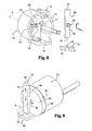
- an electrical switch arrangement according to the invention has been represented, produced in the form of a unitary component 10 notably comprising a cylindrical housing 12 that is open axially towards the front on its main horizontal and longitudinal axis A.
- the housing 12 is a plastic moulded part comprising a transversal end rear wall 11 and, also, a cylindrical lateral wall 14 delimited axially towards the front by a transversal edge 16.
- the lateral wall 14 comprises a flat horizontal lower bottom section 18 and a parallel flat horizontal top section 20.
- the housing 12 here comprises three elastically-deformable axial arms 22, each of which is terminated by a hook 24 with an end ramp 26, the functions of which will be explained below.
- the inner transversal face 28 of the transversal wall 121 comprises three radial arms, forming reinforcing ribs, arranged in a star at 120 degrees.
- the inner face 28 also comprises a cylindrical central pivot 32 of axis A which extends by protruding axially towards the front.
- the horizontal arm 30 on the left, referring to Figure 7 includes a notch 31 which is vertically aligned with a vertically-emerging opening 36, of rectangular contour, formed in the horizontal top wall 20.
- the bottom transversal wall comprises, horizontally on the left and between two radial arms 30 with reference to Figure 7 , a spring-forming elastic tab 38, the free end 40 of which is rounded and protrudes axially towards the front inside the housing 20.
- the lateral wall 14 of the housing 20 delimits an inner cylindrical housing which is open axially towards the front.
- the bottom horizontal portion 18 constitutes a reinforcement which bears an electrical switch with tactile effect 42, of known general design, of which the plinth or base, 44, is fixed in the housing 20 on the reinforcement-forming bottom portion 18.
- the electrical switch with tactile effect 42 comprises a top push button 46 for its actuation, from top to bottom, in the vertical direction V.
- the push button 46 of the switch 42 When in position mounted in the housing, the push button 46 of the switch 42 is aligned vertically with the notch 31 and with the opening 36.
- a force transmission member 50 is provided which is here a vertical rod of rectangular section which is mounted to slide in the housing 20, in a vertical direction of displacement which is orthogonal to the horizontal axis A.
- the displacements of the transmission member 50 relative to the housing 20 are guided notably by the opening 46.
- the transmission member 50 comprises a bottom proximal end 52 which cooperates with the switch 42 by bearing against the top end of the push button 46 and it comprises a top distal end 54 suitable for receiving an actuation force F.
- the force transmission member 50 bears, by its transversal and rear vertical face 56, axially towards the rear against the corresponding rear bottom edges of the notch 31 and of the opening 36.
- the force transmission member 50 On its front vertical face 58, the force transmission member 50 comprises a link axial finger which extends axially towards the front 60.
- the housing 12 also houses a disc 62 delimited by a rear transversal face 64 and by a front transversal face 66.
- the disc 62 is a part made of a magnetic material, that is to say susceptible to magnetic attraction by a magnetic field which, within the meaning of the invention, constitutes a magnetic link part or member which is linked in displacement, one-to-one, with the force transmission member 50.
- the disc 62 comprises a rear central hole 68 in which the pivot 32 is received so as to constitute means for mounting the disc 62 to pivot relative to the housing 12, in both directions, about the axis A.
- the rear face 64 also comprises a linking axial cylindrical hole 70 which receives the link axial finger 60 of the force transmission member 50.
- the rear face 64 of the magnetic disc 62 is pressed axially without play against the front vertical transversal face 58 of the force transmission member 50.
- the link in displacement of the force transmission member 50 and of the disc 62 is such that the angular pivoting in either direction of the disc 62 about the axis A corresponds to an upwards or downwards vertical displacement of the force transmission member 50.
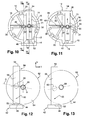
- Figure 12 schematically shows the relative position of the different components when the assembly is at rest, that is to say when the force transmission member 50 is in its high rest position with its bottom proximal end 52 bearing on the actuation push button 46 of the electrical switch with tactile effect 42.
- any vertical displacement of the force transmission member 50 corresponds to a pivoting angular displacement of the disc 62 about the axis A.
- This maximum angular travel of the disc 62 about the axis A is represented and can be seen in Figures 12 and 13 by the angular displacement of the straight line D passing through the axis of the link finger 60 and of the hole 70 and, also, through the axis A.
- controlled magnetic means are provided for angularly retaining the link magnetic disc 62 in a determined angular position.
- these controlled means consist of the subassembly 72 which incorporates, on the one hand, at its rear axial end, a permanent magnet 72A and, at its front axial end, a controlled electromagnet 72B.
- These two components 72A, 72B associated and integrated in the subassembly 72 constitute a so-called current-breaking "magnetic sucker", for example of the type marketed under the brand name “Lux'On” (registered trademark) by the company LUXALP.
- Such a subassembly 72 requires no electrical power supply and therefore also involves no electrical consumption, when in use, as long as the winding of the rear electromagnet is not powered.
- the rear permanent magnet 72A exerts a permanent field on the disc made of magnetic material 62.
- the rear section of the subassembly 72 is housed in the housing 12 and its front end transversal face 74 bears axially without play pressed against the front transversal face 66 of the disc made of magnetic material 62.
- All of the components, and notably the magnetic disc 62 and the electromagnetic sucker-forming subassembly 72 are held pressed axially in the housing by the arms 22 with their hooks 24 which bear against the front end transversal face 76 of the subassembly 72.
- the elastic tab 38 In order to ensure that there is no axial play between these components, the elastic tab 38, with its rounded end 40, ensures a forward axial thrust against the components, serving to take up play.
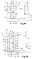
- Figure 16 schematically represents a control device 100, of the type of that described in the preamble of the present description, essentially consisting of a moving top panel 110 which can be displaced vertically relative to a bottom plate 112.
- an electrical switch arrangement 10 is housed inside the device 100 and is interposed vertically between the plate 112 and the top panel 110.Thus, the force transmission member 50 is interposed vertically between the inner face of the top panel 110 and the bottom plate 112.
- the electromagnet 72B of the subassembly 72 is controlled so as to be powered by electricity to release the link disc 62 in order to allow the downward vertical displacement of the force transmission member 50 to actuate the electrical switch with tactile effect.
- the force transmission member may be made of a magnetic material, the permanent magnet then cooperating directly with this member to slow it down.
- the direction of displacement of the transmission member 50 is not necessarily parallel to the direction of actuation of the switch 42.
- the electrical switch with tactile effect 42 does not necessarily comprise an actuation push button, the proximal end 54 being able to cooperate directly with the bistable triggering member ensuring the electrical switch and tactile effect generating function.
Landscapes
- Switch Cases, Indication, And Locking (AREA)
- User Interface Of Digital Computer (AREA)
- Push-Button Switches (AREA)
- Mechanical Control Devices (AREA)
Applications Claiming Priority (1)
| Application Number | Priority Date | Filing Date | Title |
|---|---|---|---|
| FR1262312A FR2999779B1 (fr) | 2012-12-19 | 2012-12-19 | "agencement de commutateur electrique et dispositif pour la commande d'un appareil comportant un tel agencement" |
Publications (2)
| Publication Number | Publication Date |
|---|---|
| EP2747106A1 true EP2747106A1 (fr) | 2014-06-25 |
| EP2747106B1 EP2747106B1 (fr) | 2015-05-20 |
Family
ID=48040353
Family Applications (1)
| Application Number | Title | Priority Date | Filing Date |
|---|---|---|---|
| EP20130196809 Not-in-force EP2747106B1 (fr) | 2012-12-19 | 2013-12-12 | Agencement de commutateur électrique et dispositif pour la commande d'un appareil comportant un tel agencement |
Country Status (4)
| Country | Link |
|---|---|
| US (1) | US9058946B2 (fr) |
| EP (1) | EP2747106B1 (fr) |
| CN (1) | CN103887092B (fr) |
| FR (1) | FR2999779B1 (fr) |
Families Citing this family (3)
| Publication number | Priority date | Publication date | Assignee | Title |
|---|---|---|---|---|
| CN104933831A (zh) * | 2015-07-17 | 2015-09-23 | 成都汉康信息产业有限公司 | 地质灾害监测站保护设备 |
| US10698489B1 (en) * | 2018-04-03 | 2020-06-30 | Apple Inc. | Compact pivoting input device |
| CN113223876B (zh) * | 2021-04-14 | 2023-03-21 | 国网河北省电力有限公司保定供电分公司 | 开关控制装置 |
Citations (3)
| Publication number | Priority date | Publication date | Assignee | Title |
|---|---|---|---|---|
| US20080197004A1 (en) * | 2007-02-20 | 2008-08-21 | Kabushiki Kaisha Tokai Rika Denki Seisakusho | Control switch apparatus |
| FR2947645B1 (fr) | 2009-07-01 | 2011-06-10 | Coactive Technologies Inc | Dispositif de commande comportant un panneau superieur mobile et des bras d'actionnement d'un interrupteur de commutation |
| DE102010026910A1 (de) | 2010-07-13 | 2011-08-25 | Daimler AG, 70327 | Steuern und Auslesen eines Bedienfelds |
Family Cites Families (24)
| Publication number | Priority date | Publication date | Assignee | Title |
|---|---|---|---|---|
| US3988710A (en) * | 1975-11-24 | 1976-10-26 | Illinois Tool Works Inc. | Contactless linear rotary potentiometer |
| US4293837A (en) * | 1980-07-23 | 1981-10-06 | The Singer Company | Hall effect potentiometer |
| US4871992A (en) * | 1988-07-08 | 1989-10-03 | Petersen Robert C | Tactile display apparatus |
| US4977298A (en) * | 1989-09-08 | 1990-12-11 | Matsushita Electric Industrial Co., Ltd. | Panel switch |
| US5121091A (en) * | 1989-09-08 | 1992-06-09 | Matsushita Electric Industrial Co., Ltd. | Panel switch |
| US5172092A (en) * | 1990-04-26 | 1992-12-15 | Motorola, Inc. | Selective call receiver having audible and tactile alerts |
| US5327120A (en) * | 1992-07-06 | 1994-07-05 | Motorola, Inc. | Stabilized electromagnetic resonant armature tactile vibrator |
| US5666096A (en) * | 1995-06-02 | 1997-09-09 | Van Zeeland; Anthony J. | Switch with magnetically-coupled armature |
| US5867082A (en) * | 1995-06-02 | 1999-02-02 | Duraswitch, Inc. | Switch with magnetically-coupled armature |
| KR100197156B1 (ko) * | 1996-03-22 | 1999-06-15 | 박원훈 | 자석의 반발력을 이용한 원격조종 로봇용 촉각 궤환장치 |
| US6636197B1 (en) * | 1996-11-26 | 2003-10-21 | Immersion Corporation | Haptic feedback effects for control, knobs and other interface devices |
| US7038667B1 (en) * | 1998-10-26 | 2006-05-02 | Immersion Corporation | Mechanisms for control knobs and other interface devices |
| US6556005B1 (en) * | 2000-01-27 | 2003-04-29 | Goodrich Avionics Systems, Inc. | Magnetic encoder apparatus capable of resolving axial and rotational displacements |
| US6734785B2 (en) * | 2000-10-27 | 2004-05-11 | Robert C. Petersen | Tactile display system |
| US6752637B2 (en) * | 2001-02-06 | 2004-06-22 | Ford Global Technologies, Llc | Flexible circuit relay |
| US6734776B2 (en) * | 2002-03-13 | 2004-05-11 | Ford Global Technologies, Llc | Flex circuit relay |
| US6816049B2 (en) * | 2002-09-19 | 2004-11-09 | Fuji Xerox Co., Ltd. | Actuator |
| WO2008112778A2 (fr) * | 2007-03-12 | 2008-09-18 | Touchsensor Technologies Llc | Système et procédé de retour haptique |
| FR2923921B1 (fr) * | 2007-11-20 | 2009-12-18 | Dav | Module de commande a surface tactile,en particulier pour vehicule automobile |
| FR2924858B1 (fr) * | 2007-12-06 | 2011-04-01 | Coactive Technologies Inc | Commutateur electrique a actionnement lateral et ensemble comportant un tel commutateur |
| AR074047A1 (es) * | 2008-09-09 | 2010-12-22 | Transcu Ltd | Sistemas, dispositivos, y metodos para suministrar energia a dispositivos, por ejemplo dispositivos de administracion transdermica y/o para controlarlos |
| FR2967291B1 (fr) * | 2010-11-09 | 2018-01-05 | Coactive Technologies, Inc | Commutateur electrique mince |
| KR20120071895A (ko) * | 2010-12-23 | 2012-07-03 | 한국전자통신연구원 | 촉감 제시 장치, 촉감 셀, 및 촉감 제시 장치를 제어하는 방법 |
| US20140125471A1 (en) * | 2012-11-05 | 2014-05-08 | Advanced Input Devices, Inc. | Haptic feedback systems and methods |
-
2012
- 2012-12-19 FR FR1262312A patent/FR2999779B1/fr not_active Expired - Fee Related
-
2013
- 2013-12-12 EP EP20130196809 patent/EP2747106B1/fr not_active Not-in-force
- 2013-12-19 US US14/134,098 patent/US9058946B2/en active Active
- 2013-12-19 CN CN201310757248.8A patent/CN103887092B/zh not_active Expired - Fee Related
Patent Citations (3)
| Publication number | Priority date | Publication date | Assignee | Title |
|---|---|---|---|---|
| US20080197004A1 (en) * | 2007-02-20 | 2008-08-21 | Kabushiki Kaisha Tokai Rika Denki Seisakusho | Control switch apparatus |
| FR2947645B1 (fr) | 2009-07-01 | 2011-06-10 | Coactive Technologies Inc | Dispositif de commande comportant un panneau superieur mobile et des bras d'actionnement d'un interrupteur de commutation |
| DE102010026910A1 (de) | 2010-07-13 | 2011-08-25 | Daimler AG, 70327 | Steuern und Auslesen eines Bedienfelds |
Also Published As
| Publication number | Publication date |
|---|---|
| US9058946B2 (en) | 2015-06-16 |
| US20140167890A1 (en) | 2014-06-19 |
| EP2747106B1 (fr) | 2015-05-20 |
| CN103887092A (zh) | 2014-06-25 |
| FR2999779B1 (fr) | 2015-02-13 |
| CN103887092B (zh) | 2018-05-08 |
| FR2999779A1 (fr) | 2014-06-20 |
Similar Documents
| Publication | Publication Date | Title |
|---|---|---|
| US8284003B2 (en) | Operating element having improved tilting haptics | |
| EP1045141B1 (fr) | Dispositif d'actionnement avec alliage à mémoire de forme | |
| CN103646826B (zh) | 一种漏电保护模块的动作机构 | |
| CN105980744B (zh) | 致动器,特别用于机动车辆的致动器 | |
| EP2747106B1 (fr) | Agencement de commutateur électrique et dispositif pour la commande d'un appareil comportant un tel agencement | |
| CN113738198A (zh) | 门锁 | |
| CN113874257B (zh) | 用于车辆的操作单元 | |
| US20140338408A1 (en) | Electronic system with locking function by electronically controlled | |
| EP2468590B1 (fr) | Commutateur de commande pour frein à main de véhicule | |
| US11396761B2 (en) | Safety switch | |
| KR102160748B1 (ko) | 조작 장치 및 그 조작 장치를 이용한 차량용 시프트 장치 | |
| EP1170692A2 (fr) | Lecteur des cartes à puce | |
| KR20070012625A (ko) | 전자 키를 이용한 차량 엔진 시동 장치 및 이를 위해사용될 키 | |
| EP3133625B1 (fr) | Mécanisme d'accélération, générateur de puissance, transmetteur et agencement de commutation | |
| CN108463786A (zh) | 包括用于输出触觉反馈的驱动单元的用于机动车辆的操作者单元和机动车辆 | |
| US9245701B2 (en) | Pressure switch for a motor vehicle | |
| JP2013156673A (ja) | 手書入力機能付き操作装置 | |
| CN102956395B (zh) | 一种翘板开关 | |
| US20250271891A1 (en) | Push-button | |
| CN108487797B (zh) | 一种指纹锁结构及指纹锁笔记本 | |
| CN215883515U (zh) | 盖板锁止结构和车辆 | |
| EP2571038B1 (fr) | Dispositif commutateur à glissière | |
| EP3431317B1 (fr) | Dispositif de changement de vitesse | |
| CN209942425U (zh) | 一种锁装置及保险箱 | |
| EP3736656B1 (fr) | Dispositif d'actionnement |
Legal Events
| Date | Code | Title | Description |
|---|---|---|---|
| PUAI | Public reference made under article 153(3) epc to a published international application that has entered the european phase |
Free format text: ORIGINAL CODE: 0009012 |
|
| 17P | Request for examination filed |
Effective date: 20131212 |
|
| AK | Designated contracting states |
Kind code of ref document: A1 Designated state(s): AL AT BE BG CH CY CZ DE DK EE ES FI FR GB GR HR HU IE IS IT LI LT LU LV MC MK MT NL NO PL PT RO RS SE SI SK SM TR |
|
| AX | Request for extension of the european patent |
Extension state: BA ME |
|
| R17P | Request for examination filed (corrected) |
Effective date: 20141002 |
|
| RBV | Designated contracting states (corrected) |
Designated state(s): AL AT BE BG CH CY CZ DE DK EE ES FI FR GB GR HR HU IE IS IT LI LT LU LV MC MK MT NL NO PL PT RO RS SE SI SK SM TR |
|
| GRAP | Despatch of communication of intention to grant a patent |
Free format text: ORIGINAL CODE: EPIDOSNIGR1 |
|
| RIC1 | Information provided on ipc code assigned before grant |
Ipc: H01H 9/24 20060101AFI20150107BHEP Ipc: H01H 13/00 20060101ALN20150107BHEP |
|
| RIC1 | Information provided on ipc code assigned before grant |
Ipc: H01H 9/24 20060101AFI20150112BHEP Ipc: H01H 13/00 20060101ALN20150112BHEP |
|
| INTG | Intention to grant announced |
Effective date: 20150129 |
|
| GRAS | Grant fee paid |
Free format text: ORIGINAL CODE: EPIDOSNIGR3 |
|
| GRAA | (expected) grant |
Free format text: ORIGINAL CODE: 0009210 |
|
| AK | Designated contracting states |
Kind code of ref document: B1 Designated state(s): AL AT BE BG CH CY CZ DE DK EE ES FI FR GB GR HR HU IE IS IT LI LT LU LV MC MK MT NL NO PL PT RO RS SE SI SK SM TR |
|
| REG | Reference to a national code |
Ref country code: GB Ref legal event code: FG4D |
|
| REG | Reference to a national code |
Ref country code: CH Ref legal event code: EP |
|
| REG | Reference to a national code |
Ref country code: AT Ref legal event code: REF Ref document number: 728114 Country of ref document: AT Kind code of ref document: T Effective date: 20150615 |
|
| REG | Reference to a national code |
Ref country code: IE Ref legal event code: FG4D |
|
| REG | Reference to a national code |
Ref country code: DE Ref legal event code: R096 Ref document number: 602013001808 Country of ref document: DE |
|
| REG | Reference to a national code |
Ref country code: AT Ref legal event code: MK05 Ref document number: 728114 Country of ref document: AT Kind code of ref document: T Effective date: 20150520 |
|
| REG | Reference to a national code |
Ref country code: LT Ref legal event code: MG4D |
|
| REG | Reference to a national code |
Ref country code: NL Ref legal event code: MP Effective date: 20150520 |
|
| PG25 | Lapsed in a contracting state [announced via postgrant information from national office to epo] |
Ref country code: HR Free format text: LAPSE BECAUSE OF FAILURE TO SUBMIT A TRANSLATION OF THE DESCRIPTION OR TO PAY THE FEE WITHIN THE PRESCRIBED TIME-LIMIT Effective date: 20150520 Ref country code: NO Free format text: LAPSE BECAUSE OF FAILURE TO SUBMIT A TRANSLATION OF THE DESCRIPTION OR TO PAY THE FEE WITHIN THE PRESCRIBED TIME-LIMIT Effective date: 20150820 Ref country code: LT Free format text: LAPSE BECAUSE OF FAILURE TO SUBMIT A TRANSLATION OF THE DESCRIPTION OR TO PAY THE FEE WITHIN THE PRESCRIBED TIME-LIMIT Effective date: 20150520 Ref country code: FI Free format text: LAPSE BECAUSE OF FAILURE TO SUBMIT A TRANSLATION OF THE DESCRIPTION OR TO PAY THE FEE WITHIN THE PRESCRIBED TIME-LIMIT Effective date: 20150520 Ref country code: ES Free format text: LAPSE BECAUSE OF FAILURE TO SUBMIT A TRANSLATION OF THE DESCRIPTION OR TO PAY THE FEE WITHIN THE PRESCRIBED TIME-LIMIT Effective date: 20150520 Ref country code: PT Free format text: LAPSE BECAUSE OF FAILURE TO SUBMIT A TRANSLATION OF THE DESCRIPTION OR TO PAY THE FEE WITHIN THE PRESCRIBED TIME-LIMIT Effective date: 20150921 |
|
| PG25 | Lapsed in a contracting state [announced via postgrant information from national office to epo] |
Ref country code: LV Free format text: LAPSE BECAUSE OF FAILURE TO SUBMIT A TRANSLATION OF THE DESCRIPTION OR TO PAY THE FEE WITHIN THE PRESCRIBED TIME-LIMIT Effective date: 20150520 Ref country code: IS Free format text: LAPSE BECAUSE OF FAILURE TO SUBMIT A TRANSLATION OF THE DESCRIPTION OR TO PAY THE FEE WITHIN THE PRESCRIBED TIME-LIMIT Effective date: 20150920 Ref country code: AT Free format text: LAPSE BECAUSE OF FAILURE TO SUBMIT A TRANSLATION OF THE DESCRIPTION OR TO PAY THE FEE WITHIN THE PRESCRIBED TIME-LIMIT Effective date: 20150520 Ref country code: GR Free format text: LAPSE BECAUSE OF FAILURE TO SUBMIT A TRANSLATION OF THE DESCRIPTION OR TO PAY THE FEE WITHIN THE PRESCRIBED TIME-LIMIT Effective date: 20150821 Ref country code: BG Free format text: LAPSE BECAUSE OF FAILURE TO SUBMIT A TRANSLATION OF THE DESCRIPTION OR TO PAY THE FEE WITHIN THE PRESCRIBED TIME-LIMIT Effective date: 20150820 Ref country code: RS Free format text: LAPSE BECAUSE OF FAILURE TO SUBMIT A TRANSLATION OF THE DESCRIPTION OR TO PAY THE FEE WITHIN THE PRESCRIBED TIME-LIMIT Effective date: 20150520 |
|
| REG | Reference to a national code |
Ref country code: FR Ref legal event code: PLFP Year of fee payment: 3 |
|
| PG25 | Lapsed in a contracting state [announced via postgrant information from national office to epo] |
Ref country code: DK Free format text: LAPSE BECAUSE OF FAILURE TO SUBMIT A TRANSLATION OF THE DESCRIPTION OR TO PAY THE FEE WITHIN THE PRESCRIBED TIME-LIMIT Effective date: 20150520 Ref country code: EE Free format text: LAPSE BECAUSE OF FAILURE TO SUBMIT A TRANSLATION OF THE DESCRIPTION OR TO PAY THE FEE WITHIN THE PRESCRIBED TIME-LIMIT Effective date: 20150520 |
|
| REG | Reference to a national code |
Ref country code: DE Ref legal event code: R097 Ref document number: 602013001808 Country of ref document: DE |
|
| PG25 | Lapsed in a contracting state [announced via postgrant information from national office to epo] |
Ref country code: SK Free format text: LAPSE BECAUSE OF FAILURE TO SUBMIT A TRANSLATION OF THE DESCRIPTION OR TO PAY THE FEE WITHIN THE PRESCRIBED TIME-LIMIT Effective date: 20150520 Ref country code: RO Free format text: LAPSE BECAUSE OF NON-PAYMENT OF DUE FEES Effective date: 20150520 Ref country code: CZ Free format text: LAPSE BECAUSE OF FAILURE TO SUBMIT A TRANSLATION OF THE DESCRIPTION OR TO PAY THE FEE WITHIN THE PRESCRIBED TIME-LIMIT Effective date: 20150520 Ref country code: PL Free format text: LAPSE BECAUSE OF FAILURE TO SUBMIT A TRANSLATION OF THE DESCRIPTION OR TO PAY THE FEE WITHIN THE PRESCRIBED TIME-LIMIT Effective date: 20150520 |
|
| PLBE | No opposition filed within time limit |
Free format text: ORIGINAL CODE: 0009261 |
|
| STAA | Information on the status of an ep patent application or granted ep patent |
Free format text: STATUS: NO OPPOSITION FILED WITHIN TIME LIMIT |
|
| 26N | No opposition filed |
Effective date: 20160223 |
|
| PG25 | Lapsed in a contracting state [announced via postgrant information from national office to epo] |
Ref country code: IT Free format text: LAPSE BECAUSE OF FAILURE TO SUBMIT A TRANSLATION OF THE DESCRIPTION OR TO PAY THE FEE WITHIN THE PRESCRIBED TIME-LIMIT Effective date: 20150520 |
|
| PG25 | Lapsed in a contracting state [announced via postgrant information from national office to epo] |
Ref country code: BE Free format text: LAPSE BECAUSE OF NON-PAYMENT OF DUE FEES Effective date: 20151231 Ref country code: SI Free format text: LAPSE BECAUSE OF FAILURE TO SUBMIT A TRANSLATION OF THE DESCRIPTION OR TO PAY THE FEE WITHIN THE PRESCRIBED TIME-LIMIT Effective date: 20150520 |
|
| PG25 | Lapsed in a contracting state [announced via postgrant information from national office to epo] |
Ref country code: LU Free format text: LAPSE BECAUSE OF FAILURE TO SUBMIT A TRANSLATION OF THE DESCRIPTION OR TO PAY THE FEE WITHIN THE PRESCRIBED TIME-LIMIT Effective date: 20151212 Ref country code: MC Free format text: LAPSE BECAUSE OF FAILURE TO SUBMIT A TRANSLATION OF THE DESCRIPTION OR TO PAY THE FEE WITHIN THE PRESCRIBED TIME-LIMIT Effective date: 20150520 |
|
| PG25 | Lapsed in a contracting state [announced via postgrant information from national office to epo] |
Ref country code: BE Free format text: LAPSE BECAUSE OF FAILURE TO SUBMIT A TRANSLATION OF THE DESCRIPTION OR TO PAY THE FEE WITHIN THE PRESCRIBED TIME-LIMIT Effective date: 20150520 |
|
| REG | Reference to a national code |
Ref country code: IE Ref legal event code: MM4A |
|
| PG25 | Lapsed in a contracting state [announced via postgrant information from national office to epo] |
Ref country code: IE Free format text: LAPSE BECAUSE OF NON-PAYMENT OF DUE FEES Effective date: 20151212 |
|
| REG | Reference to a national code |
Ref country code: FR Ref legal event code: PLFP Year of fee payment: 4 |
|
| PG25 | Lapsed in a contracting state [announced via postgrant information from national office to epo] |
Ref country code: HU Free format text: LAPSE BECAUSE OF FAILURE TO SUBMIT A TRANSLATION OF THE DESCRIPTION OR TO PAY THE FEE WITHIN THE PRESCRIBED TIME-LIMIT; INVALID AB INITIO Effective date: 20131212 |
|
| PG25 | Lapsed in a contracting state [announced via postgrant information from national office to epo] |
Ref country code: SE Free format text: LAPSE BECAUSE OF FAILURE TO SUBMIT A TRANSLATION OF THE DESCRIPTION OR TO PAY THE FEE WITHIN THE PRESCRIBED TIME-LIMIT Effective date: 20150520 Ref country code: NL Free format text: LAPSE BECAUSE OF FAILURE TO SUBMIT A TRANSLATION OF THE DESCRIPTION OR TO PAY THE FEE WITHIN THE PRESCRIBED TIME-LIMIT Effective date: 20150520 Ref country code: CY Free format text: LAPSE BECAUSE OF FAILURE TO SUBMIT A TRANSLATION OF THE DESCRIPTION OR TO PAY THE FEE WITHIN THE PRESCRIBED TIME-LIMIT Effective date: 20150520 |
|
| REG | Reference to a national code |
Ref country code: CH Ref legal event code: PL |
|
| PG25 | Lapsed in a contracting state [announced via postgrant information from national office to epo] |
Ref country code: MT Free format text: LAPSE BECAUSE OF FAILURE TO SUBMIT A TRANSLATION OF THE DESCRIPTION OR TO PAY THE FEE WITHIN THE PRESCRIBED TIME-LIMIT Effective date: 20150520 |
|
| PG25 | Lapsed in a contracting state [announced via postgrant information from national office to epo] |
Ref country code: CH Free format text: LAPSE BECAUSE OF NON-PAYMENT OF DUE FEES Effective date: 20161231 Ref country code: LI Free format text: LAPSE BECAUSE OF NON-PAYMENT OF DUE FEES Effective date: 20161231 |
|
| REG | Reference to a national code |
Ref country code: FR Ref legal event code: PLFP Year of fee payment: 5 |
|
| PG25 | Lapsed in a contracting state [announced via postgrant information from national office to epo] |
Ref country code: SM Free format text: LAPSE BECAUSE OF FAILURE TO SUBMIT A TRANSLATION OF THE DESCRIPTION OR TO PAY THE FEE WITHIN THE PRESCRIBED TIME-LIMIT Effective date: 20150520 |
|
| PG25 | Lapsed in a contracting state [announced via postgrant information from national office to epo] |
Ref country code: MK Free format text: LAPSE BECAUSE OF FAILURE TO SUBMIT A TRANSLATION OF THE DESCRIPTION OR TO PAY THE FEE WITHIN THE PRESCRIBED TIME-LIMIT Effective date: 20150520 |
|
| GBPC | Gb: european patent ceased through non-payment of renewal fee |
Effective date: 20171212 |
|
| PG25 | Lapsed in a contracting state [announced via postgrant information from national office to epo] |
Ref country code: AL Free format text: LAPSE BECAUSE OF FAILURE TO SUBMIT A TRANSLATION OF THE DESCRIPTION OR TO PAY THE FEE WITHIN THE PRESCRIBED TIME-LIMIT Effective date: 20150520 Ref country code: TR Free format text: LAPSE BECAUSE OF FAILURE TO SUBMIT A TRANSLATION OF THE DESCRIPTION OR TO PAY THE FEE WITHIN THE PRESCRIBED TIME-LIMIT Effective date: 20150520 |
|
| PG25 | Lapsed in a contracting state [announced via postgrant information from national office to epo] |
Ref country code: GB Free format text: LAPSE BECAUSE OF NON-PAYMENT OF DUE FEES Effective date: 20171212 |
|
| P01 | Opt-out of the competence of the unified patent court (upc) registered |
Effective date: 20230607 |
|
| PGFP | Annual fee paid to national office [announced via postgrant information from national office to epo] |
Ref country code: FR Payment date: 20231009 Year of fee payment: 11 Ref country code: DE Payment date: 20231017 Year of fee payment: 11 |
|
| REG | Reference to a national code |
Ref country code: DE Ref legal event code: R119 Ref document number: 602013001808 Country of ref document: DE |
|
| PG25 | Lapsed in a contracting state [announced via postgrant information from national office to epo] |
Ref country code: DE Free format text: LAPSE BECAUSE OF NON-PAYMENT OF DUE FEES Effective date: 20250701 |
|
| PG25 | Lapsed in a contracting state [announced via postgrant information from national office to epo] |
Ref country code: FR Free format text: LAPSE BECAUSE OF NON-PAYMENT OF DUE FEES Effective date: 20241231 |