EP2747599B1 - Dispositif pour raccorder une façade à un châssis - Google Patents
Dispositif pour raccorder une façade à un châssis Download PDFInfo
- Publication number
- EP2747599B1 EP2747599B1 EP12778958.4A EP12778958A EP2747599B1 EP 2747599 B1 EP2747599 B1 EP 2747599B1 EP 12778958 A EP12778958 A EP 12778958A EP 2747599 B1 EP2747599 B1 EP 2747599B1
- Authority
- EP
- European Patent Office
- Prior art keywords
- frame
- fastening
- adjusting
- hook
- designed
- Prior art date
- Legal status (The legal status is an assumption and is not a legal conclusion. Google has not performed a legal analysis and makes no representation as to the accuracy of the status listed.)
- Active
Links
Images



Classifications
-
- A—HUMAN NECESSITIES
- A47—FURNITURE; DOMESTIC ARTICLES OR APPLIANCES; COFFEE MILLS; SPICE MILLS; SUCTION CLEANERS IN GENERAL
- A47B—TABLES; DESKS; OFFICE FURNITURE; CABINETS; DRAWERS; GENERAL DETAILS OF FURNITURE
- A47B88/00—Drawers for tables, cabinets or like furniture; Guides for drawers
- A47B88/90—Constructional details of drawers
- A47B88/944—Drawers characterised by the front panel
- A47B88/95—Drawers characterised by the front panel characterised by connection means for the front panel
- A47B88/956—Drawers characterised by the front panel characterised by connection means for the front panel for enabling adjustment of the front panel
-
- A—HUMAN NECESSITIES
- A47—FURNITURE; DOMESTIC ARTICLES OR APPLIANCES; COFFEE MILLS; SPICE MILLS; SUCTION CLEANERS IN GENERAL
- A47B—TABLES; DESKS; OFFICE FURNITURE; CABINETS; DRAWERS; GENERAL DETAILS OF FURNITURE
- A47B88/00—Drawers for tables, cabinets or like furniture; Guides for drawers
- A47B88/90—Constructional details of drawers
- A47B88/944—Drawers characterised by the front panel
- A47B88/95—Drawers characterised by the front panel characterised by connection means for the front panel
Definitions
- the invention relates to a device for connecting a front with a frame, with a fastening device, via the front and the frame are fastened to each other.
- Such a device is known for example from AT 409 070 B.
- the device described therein is intended for use in a frame designed as a hollow chamber frame. It is provided a central hooking element, which is arranged in the middle of the height of the hollow chamber frame and serves to connect the front.
- a central hooking element which is arranged in the middle of the height of the hollow chamber frame and serves to connect the front.
- EP 1 516 561 WO 2010/136228 .
- WO2008 / 010036
- the object of the invention is to provide a device for connecting a front with a frame of the type mentioned, with the front panels with a relatively large height can be reliably and stably fixed to the frame and thereby fronts can be mounted regardless of the frame type.
- the device according to the invention is characterized in that the fastening device has at least two fastening units which lie one above the other in the vertical direction of the front and allow attachment of the front and the frame to each other at at least two fastening interfaces spaced apart from one another in the vertical direction.
- the front is thus coupled to at least two attachment interfaces with the frame, which increases the stability of the connection of the front and the frame.
- fronts with high overall height can be reliably and stably connected to the associated frame.
- the fastening units for a releasable attachment of the front and frame are set.
- a quick disassembly of the front of the frame is possible, for example, if the front is damaged and should be replaced.
- the fastening units are operatively connected to one another via operative connection means in such a manner that fastening or releasing the one fastening unit effects attachment or detachment of the other fastening unit.
- An attachment and / or release action is therefore only necessary on a fastening interface and thus on a fastening unit, since the other fastening unit is activated by means of the active connection means.
- the operative connection means have at least one movement coupling the two fastening units together Coupling on.
- the coupling member may be formed, for example, as a coupling rod.
- the fastening device is designed in several parts, with one of the frame associated frame-side mounting module and the front associated front mounting module, wherein associated components of the fastening units are arranged on the one hand on the frame side mounting module and on the other hand on the front mounting module.
- the fastening units each have at least one suspension element and at least one suspension hook which can be hooked into the suspension element, preferably a hook-like recess.
- the suspension elements are preferably located on the frame-side fastening module.
- the suspension elements can be adapted to the shape of a hook-like recess designed as a hook, so that the suspension element sits snugly in the hook-like recess.
- the active connection means are expediently arranged on the frame side mounting module. Again, an arrangement on the front mounting module would be possible.
- the active connection means have element carriers on which in each case one of the suspension elements or in each case one of the suspension hooks is arranged and which are connected to one another by means of the coupling element.
- the element carriers are over bearing means movably mounted. It can be provided, for example, a kind of slide with the two element carriers and the coupling member, wherein the carriage on a base body, which is in particular part of the frame-side fixing module, is guided displaceably.
- the invention further relates to a device for connecting a front with a frame with the features of independent claim 11.
- the device is characterized in that the adjusting means are designed such that the front can be fixed to the frame via the adjusting means.
- the adjusting means are therefore multifunctional and serve both to adjust the front in relation to the frame and for fixing the front to the frame.
- the adjusting means are expediently components of a fastening device according to one or more of the features of claims 1 to 8.
- the multifunctional adjustment means allow the attachment of the front to the frame regardless of Zargentyp. It must be fixed to the frame only the adjusting / fixing. There are no Zarg typical built-in parts necessary.
- the adjusting means comprise a 9.verstellech for adjusting the lateral position of the front with respect to the frame.
- the adjusting means may have at least one adjustment element mounted adjustably in a wall of a frame formed as a hollow-chamber frame and transversely to the longitudinal direction of the frame.
- the adjusting element may be formed, for example, as an adjusting screw.
- the adjusting screw can be operated through an operating opening in the Zargenwandung and can therefore be easily reached from outside the frame ago.
- the adjustment elements are expediently the attachment elements assigned to the attachment units.
- the adjusting means may comprise a height adjustment unit for height adjustment of the front with respect to the frame.
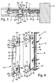
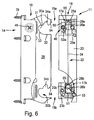
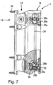
- FIGS. 1 to 8 show a preferred embodiment of the device 11 according to the invention, which serves to connect a front 12 with a frame 13.
- Both the front 12, which is configured in the example as a front panel, as well as the frame 13 are components of a drawer or a drawer. Therefore, the front 12 at two opposite frames 13, that is to be attached to a left and right frame 13, to be attached.
- the in the FIGS. 1 to 8 shown inventive device 11 may therefore be identical to the other frame 13 in the example. The construction described below and the mode of operation of the device 11 therefore also apply to the other frame 13 in the same way.
- the frame 13 is designed according to example as a hollow chamber frame.
- the hollow chamber frame can be designed as an extruded profile.
- extruded material is aluminum.
- the front 12 is According to embodiment, a front panel, which may for example consist of wood or metal.
- the device 11 comprises a fastening device 14, via the front 12 and the frame 13 are fastened to each other.
- the fastening device 14 has at least two attachment units 15a, 15b which lie one above the other in the vertical direction of the front 12 and via which the attachment of the front 12 and the frame 13 to each other can be carried out on at least two attachment interfaces 17a, 17b spaced from one another in the vertical direction.
- the fastening device 14 further comprises a frame-side fastening module 18 assigned to the frame 13 and a front-side fastening module 19 assigned to the front 12.
- the frame-side mounting module 18 has a base body 20, in particular of sheet metal material.
- One of the side edges of the base body 20 extends at an angle to the rest of the main body 20 and forms a groove 21, in which components of operative connection means 22, which connect the two fastening units 15a, 15b are used together.
- the operative connection means 22 in this case comprise two element carriers 23a, 23b, each associated with one of the fastening units 15a, 15b, in each of which a latching element 25a, 25b is movably guided by means of a guide arrangement 50.
- the two latching members 25a, 25b are connected to each other via a coupling rod 24 and therefore together with the coupling rod 24 form a kind of adjusting slide.
- the coupling rod 24 is shown by way of example as a push rod, which is in touching contact with the two locking members 25a, 25b.
- the coupling rod 24 may be formed as a pull rod, but this requires a different operation compared to the push rod.
- the two locking members 25a, 25b each have longitudinal sides, which are formed as a kind of rack 26a, 26b. Overall, the locking members 25a, 25b sit between the associated element carriers 23a, 23b and the base body 20.
- the racks 26a, 26b are accessible via a window-like opening 51 from the side of the element carriers 23a, 23b. In the intended mounting position in the frame at least one of the window-like opening 51 is associated with a formed in the frame wall operating openings 27, intervened with a suitable tool, such as screwdriver, in the rack 26 and by turning the screwdriver a linear adjustment movement of the locking member 25 a, 25b can be triggered, resulting in the dissolution process described in more detail below.
- a suitable tool such as screwdriver
- the frame members 23a, 23b are associated with the frame-side components of the fastening units 18, namely the hook-in elements 28a, 28b, which are designed according to the preferred embodiment as hook-in cams.
- the suspension cams are located on the top of the latch members 25a, 25b associated with the element carrier 23a, 23b. At least one locking cam and thus the associated locking member 25a and the coupling rod 24 and the other locking member 25b is subjected to force, whereby the two locking cams are held in an insertion position.
- the application of force can take place, for example, by means of a spring element 53, for example as a helical torsion spring, which, on the other hand, is supported on the main body 20.
- a spring element 53 for example as a helical torsion spring
- components of the fastening units 15a, 15b are components of adjusting means 40, via which the front 12 can be adjusted with respect to the frame 13.
- the adjusting means 40 comprise a soverstelltechnik 41, the essential components include adjusting elements 52a, 52b, which are exemplified as adjusting screws.
- the fastening units are therefore multifunctional and serve on the one hand for fixing the front 12 on the frame 13 and on the other for lateral adjustment of the front 12 in relation to the frame 13th
- the adjusting screws respectively pass through the associated element carrier 23a, 23b and, as in FIGS Fig. 2 and 3 shown, mounted on the one hand with a screw head 42 in a frame wall in an operating opening 43.
- a fixing element for example Seeger ring 44
- the adjusting screw is also stored with the screw tip at an adjustment seat 45 in the opposite other Zargenwand.
- the screw head 42 is further provided with an engagement structure, such as Keuzschlitz Weg Modell, in which a suitable adjustment tool, such as screwdriver, can engage to effect an adjustment of the front 12 relative to the frame 13.
- the adjusting screw is fixed in relation to the frame 13 via the fixing element and rotates in place, which causes a displacement of the two fastening units 15a, 15b relative to the Zargenrawn.
- the front-side mounting module 19 comprises a plate-like hanger portion 29, on which the front-side components of the fastening units 15a, 15b are formed.
- To these components include two each of the frame-side suspension elements 28a, 28b associated insertion slots 30a, 30b, which are open to the longitudinal side of the Ein vonabterrorisms 29 respectively.
- the insertion slots 30 a, 30 b each have an upper and a lower leg 31, 32, which are connected to each other via an arcuate connecting portion 33. On the upper leg 31 is located, aligned in the longitudinal direction of the Ein vonmillions 29, a hook 34 in the form of a hook-like recess.
- a mounting portion 35 connects.
- the mounting portion 35 is constructed in two parts, with a particular integrally connected to the Ein vonabrough 29 bearing section 36 and connectable to the bearing section 36 Fixierpartie 37.
- the fixing 37 has a mounting bar 38 are mounted on the fixing screws 39, which are screwed into the front of the front 12 serve.
- an adjusting portion 46 is attached to the mounting bar 38, which surrounds the bearing section 36 and engages in slot-like bearing holes 47 on Ein distrabites 29.
- a height adjustment 48 such as height adjustment screw, mounted, which cooperates with the adjustment so that adjust by rotation of the height adjustment 48 of the adjustment 46 and the coupled mounting bar 38 together with the front 12 in the height direction to the hooking portion 29 leaves.
- the frame-side mounting module 18 is first mounted within the hollow chamber frame to connect the front 12 with the frame 13.
- the mounting module 18 is inserted without the adjusting screws in the frame 13 and in the positionally accurate position with fixed the adjusting screws.
- the adjustment screws belonging to the fastening units 15a, 15b are thus screwed in from the outside via the operating openings 43 and fixed by means of the Seeger rings 44 at the two superimposed fastening interfaces 17a, 17b.
- the fastening module 18 is thus fixed in height and depth in the frame 13.
- the front 12 is connected via the mounting strip 38 and the fixing screws 39 with the front mounting module 19. Thereafter, the mounting module 19 is inserted with the hooking portion 29 in advance in the frame 13.
- inclined surfaces 54, 55 associated with each other slide on the front sides of the insertion slots 30a, 30b of the front-side attachment module 19 on the one hand, and on the latching cams on the other hand.
- the two locking members 25a, 25b are pressed against the spring force of the spring element 53 down. In the further movement snap the locking members by the support of the spring force of the spring element in the hook-like recesses, wherein the force is transmitted via the coupling rod designed as a push rod on the other, in particular upper locking member 25a, 25b.
- the two mounting modules 18, 19 are then locked together, as in Fig. 8 shown.
- the release via a, the lower rack 26b associated, further operating opening would be possible. It is intervened by means of the screwdriver in the lower rack 26b and effected by a rotation in the counterclockwise direction, a movement of the lower locking member 25b down.
- the coupling rod 24 is formed as a pull rod, whereby a power transmission to the upper locking member 25a is made possible.
- a pull rod on the one hand firmly connected to the one locking member 25a and on the other hand firmly connected to the other locking member 25b, an operating action on the upper or lower rack 26a, 26b would be possible via correspondingly associated control openings.
- the adjusting screws are turned over the operating openings 43 with a tool. Since the adjusting screws rotate in place, this causes a displacement of the two fastening modules 18, 19 and thus the coupled front 12 relative to the frame 13th
- For height adjustment is another operating opening 49 via which the height adjustment screw can be operated.
Landscapes
- Mutual Connection Of Rods And Tubes (AREA)
- Handcart (AREA)
Claims (12)
- Dispositif servant à assembler une façade (12) avec un châssis (13), comprenant un système de fixation (14), par l'intermédiaire duquel la façade (12) et le châssis (13) peuvent être fixés l'un à l'autre, sachant que le système de fixation (14) présente au moins deux unités de fixation (15a, 15b) situées l'une au-dessus de l'autre dans le sens de la hauteur de la façade (12), par l'intermédiaire desquelles une fixation de la façade (12) et du châssis (13) est possible l'un contre l'autre au niveau de deux interfaces de fixation (17a, 17b) espacées l'une de l'autre dans le sens de la hauteur, caractérisé en ce que les unités de fixation (17a, 17b) sont en liaison fonctionnelle les unes avec les autres par l'intermédiaire de moyens de liaison fonctionnelle (22) de telle manière qu'une fixation ou un détachement d'une unité de fixation (17a, 17b) provoque une fixation ou un détachement de l'autre unité de fixation (17a, 17b).
- Dispositif selon la revendication 1, caractérisé en ce que les unités de fixation (17a, 17b) sont configuées pour une fixation amovible de la façade (12) et du châssis (13).
- Dispositif selon la revendication 1 ou 2, caractérisé en ce que les moyens de liaison fonctionnelle (22) présentent au moins un organe de couplage couplant en mouvement l'une à l'autre les deux unités de fixation (17a, 17b), en particulier une barre de couplage (24).
- Dispositif selon l'une quelconque des revendications précédentes, caractérisé en ce que le dispositif de fixation (14) est réalisé en plusieurs parties, avec un module de fixation (18) côté châssis associé au châssis (13) et avec un module de fixation (19) côté façade associé à la façade (12), sachant que des composants associés les uns aux autres des unités de fixation (17a, 17b) sont disposés d'une part au niveau du module de fixation (18) côté châssis et d'autre part au niveau du module de fixation (19) côté façade.
- Dispositif selon la revendication 4, caractérisé en ce que les unités de fixation (17a, 17b) présentent respectivement en tant que composants au moins un élément d'accrochage (28a, 28b) et au moins un crochet d'accrochage (34a, 34b) pouvant être accroché dans l'élément d'accrochage (28a, 28b), sachant que de préférence les éléments d'accrochage (28a, 28b) sont disposés au niveau du module de fixation (18) côté châssis.
- Dispositif selon la revendication 4 ou 5, caractérisé en ce que les moyens de liaison fonctionnelle (22) sont disposés au niveau du module de fixation (18) côté châssis.
- Dispositif selon la revendication 5 ou 6, caractérisé en ce que les moyens de liaison fonctionnelle (22) présentent des organes d'enclenchement (25a, 25b), au niveau desquels respectivement un des éléments d'accrochage (28a, 28b) ou respectivement un des crochets d'accrochage (34a, 34b) sont disposés et qui peuvent être assemblés ou sont assemblés les uns aux autres au moyen de l'organe de couplage, sachant que de préférence les organes d'enclenchement (25a, 25b) sont montés de manière mobile par l'intermédiaire d'ensembles de guidage (50).
- Dispositif selon l'une quelconque des revendications précédentes, caractérisé par des moyens d'ajustement (40) servant à ajuster la façade (12) par rapport au châssis (13), sachant que les moyens d'ajustement (40) sont réalisés de telle manière que la façade (12) peut être fixée au niveau du châssis (13) par l'intermédiaire des moyens d'ajustement (40).
- Dispositif selon l'une quelconque des revendications précédentes, caractérisé en ce que les moyens d'ajustement (40) comprennent une unité d'ajustement latéral (41) servant à régler la position latérale de la façade (12) par rapport au châssis (13).
- Dispositif selon l'une quelconque des revendications précédentes, caractérisé en ce que les moyens d'ajustement (40) présentent au moins un élément d'ajustement monté de manière à pouvoir être ajusté de manière transversale par rapport au sens longitudinal du châssis dans une paroi d'un châssis (13) réalisé sous la forme d'un châssis à chambre creuse, en particulier une vis d'ajustement.
- Partie de meuble, en particulier tiroir, comprenant une façade (12) et deux châssis (13), en particulier des châssis à chambre creuse, caractérisée par un dispositif (11) selon l'une quelconque des revendications 1 à 10.
- Meuble comprenant au moins une partie de meuble, en particulier un tiroir, qui présente une façade (12) et deux châssis (13), caractérisé par un dispositif (11) selon l'une quelconque des revendications 1 à 10.
Applications Claiming Priority (2)
| Application Number | Priority Date | Filing Date | Title |
|---|---|---|---|
| DE202011106765U DE202011106765U1 (de) | 2011-10-14 | 2011-10-14 | Vorrichtung zur Verbindung einer Front mit einer Zarge |
| PCT/EP2012/004283 WO2013053494A2 (fr) | 2011-10-14 | 2012-10-12 | Dispositif pour raccorder une façade à un châssis |
Publications (2)
| Publication Number | Publication Date |
|---|---|
| EP2747599A2 EP2747599A2 (fr) | 2014-07-02 |
| EP2747599B1 true EP2747599B1 (fr) | 2016-06-29 |
Family
ID=47088791
Family Applications (1)
| Application Number | Title | Priority Date | Filing Date |
|---|---|---|---|
| EP12778958.4A Active EP2747599B1 (fr) | 2011-10-14 | 2012-10-12 | Dispositif pour raccorder une façade à un châssis |
Country Status (4)
| Country | Link |
|---|---|
| EP (1) | EP2747599B1 (fr) |
| DE (1) | DE202011106765U1 (fr) |
| ES (1) | ES2586600T3 (fr) |
| WO (1) | WO2013053494A2 (fr) |
Cited By (1)
| Publication number | Priority date | Publication date | Assignee | Title |
|---|---|---|---|---|
| DE102023130093A1 (de) * | 2023-10-31 | 2025-04-30 | Paul Hettich Gmbh & Co. Kg | Blendenträger |
Families Citing this family (4)
| Publication number | Priority date | Publication date | Assignee | Title |
|---|---|---|---|---|
| DE102015122192B4 (de) * | 2015-12-18 | 2024-08-08 | Paul Hettich Gmbh & Co. Kg | Vorrichtung zum lösbaren Fixieren einer Frontblende und Verfahren zum Montieren und Demontieren einer Frontblende |
| DE102018102219A1 (de) | 2018-02-01 | 2019-08-01 | Paul Hettich Gmbh & Co. Kg | Befestigungsvorrichtung für eine Blende eines Schubkastens |
| AT526394A1 (de) | 2022-07-21 | 2024-02-15 | Blum Gmbh Julius | Schubladenseitenwand für eine Schublade |
| DE102023130090A1 (de) * | 2023-10-31 | 2025-04-30 | Paul Hettich Gmbh & Co. Kg | Schubkasten mit einer Einstellvorrichtung zur Seitenverstellung der Blende |
Family Cites Families (13)
| Publication number | Priority date | Publication date | Assignee | Title |
|---|---|---|---|---|
| DE8316770U1 (de) * | 1983-06-08 | 1983-11-10 | Ninkaplast Gmbh, 4902 Bad Salzuflen | Auszug fuer schraenke |
| AT391986B (de) * | 1985-02-12 | 1990-12-27 | Blum Gmbh Julius | Befestigungsvorrichtung fuer verstellbare frontplatten |
| DE19510119B4 (de) * | 1995-03-21 | 2005-06-02 | MEPLA-WERKE LAUTENSCHLäGER GMBH & CO. KG | Schnellmontage-Befestigungsbeschlag für Schubladen-Frontblenden |
| AT409070B (de) | 1997-11-07 | 2002-05-27 | Alfit Ag | Vorrichtung zum befestigen der frontblende einer schublade |
| DE10021033A1 (de) * | 2000-05-02 | 2003-09-04 | Grass Gmbh Hoechst | Verstellvorrichtung zur Neigungsverstellung der Frontblende einer Schublade |
| EP1516561B1 (fr) * | 2003-09-18 | 2006-05-10 | Grass GmbH | Tiroir doté de parois supérieurs |
| MY140411A (en) * | 2006-07-14 | 2009-12-31 | Harn Marketing Sdn Bhd | Drawer fitting |
| MX2008006644A (es) * | 2008-05-22 | 2009-11-23 | Mabe Sa De Cv | Sistema de nivelacion para panel o cajon. |
| DE202008016758U1 (de) * | 2008-12-18 | 2010-05-12 | Paul Hettich Gmbh & Co. Kg | Verstelleinrichtung zum Ausrichten eines Möbelteils |
| DE102009025890A1 (de) * | 2009-05-29 | 2011-06-22 | Paul Hettich GmbH & Co. KG, 32278 | Vorrichtung zur Befestigung einer Frontblende an einer Seitenzarge eines beweglichen Möbelteils eines Möbels, Schubkasten und Möbel |
| DE202010000086U1 (de) * | 2010-01-27 | 2011-06-01 | Paul Hettich GmbH & Co. KG, 32278 | Schubkasten mit zwei Seitenzargen und einer Frontblende |
| AT509411B1 (de) * | 2010-02-03 | 2012-05-15 | Blum Gmbh Julius | Schubladenzarge |
| DE202010007430U1 (de) * | 2010-05-31 | 2011-09-05 | Grass Gmbh | Vorrichtung mit einer Anbringeinrichtung und Schublade |
-
2011
- 2011-10-14 DE DE202011106765U patent/DE202011106765U1/de not_active Expired - Lifetime
-
2012
- 2012-10-12 ES ES12778958.4T patent/ES2586600T3/es active Active
- 2012-10-12 WO PCT/EP2012/004283 patent/WO2013053494A2/fr not_active Ceased
- 2012-10-12 EP EP12778958.4A patent/EP2747599B1/fr active Active
Non-Patent Citations (1)
| Title |
|---|
| None * |
Cited By (2)
| Publication number | Priority date | Publication date | Assignee | Title |
|---|---|---|---|---|
| DE102023130093A1 (de) * | 2023-10-31 | 2025-04-30 | Paul Hettich Gmbh & Co. Kg | Blendenträger |
| WO2025093304A1 (fr) | 2023-10-31 | 2025-05-08 | Paul Hettich Gmbh & Co. Kg | Support de panneau |
Also Published As
| Publication number | Publication date |
|---|---|
| ES2586600T3 (es) | 2016-10-17 |
| DE202011106765U1 (de) | 2013-01-16 |
| EP2747599A2 (fr) | 2014-07-02 |
| WO2013053494A2 (fr) | 2013-04-18 |
| WO2013053494A3 (fr) | 2013-10-17 |
Similar Documents
| Publication | Publication Date | Title |
|---|---|---|
| EP2531065B1 (fr) | Châssis de tiroir | |
| EP2265147B1 (fr) | Dispositif d'expulsion verrouillable pour un élément de meuble logé mobile dans un meuble | |
| EP2747599B1 (fr) | Dispositif pour raccorder une façade à un châssis | |
| DE102009025890A1 (de) | Vorrichtung zur Befestigung einer Frontblende an einer Seitenzarge eines beweglichen Möbelteils eines Möbels, Schubkasten und Möbel | |
| EP1854373A2 (fr) | Système de table | |
| AT506543A1 (de) | Feststellvorrichtung zum arretieren eines in oder an einem möbel bewegbar gelagerten möbelteiles | |
| EP3681347B1 (fr) | Support de panneau et tiroir | |
| EP2628411A2 (fr) | Tiroir | |
| EP4385363B1 (fr) | Ensemble comprenant un dispositif d'entraînement et un dispositif de synchronisation pour glissières télescopiques d'un tiroir | |
| EP2983553B1 (fr) | Dispositif d'extraction pour coulissants de meuble | |
| DE202011001589U1 (de) | Aufhängevorrichtung für Möbel | |
| EP1900572B1 (fr) | Dispositif de déplacement de la position verticale d'une fermeture de conteneur | |
| EP2064972B1 (fr) | Tiroir d'armoire doté d'une partie de support et d'une façade de meuble pouvant être fixée dessus | |
| DE102005028573B4 (de) | Befestigungsanordnung für Möbelteile, insbesondere Tischmöbelteile | |
| EP2531072B1 (fr) | Dispositif de fixation d'une unité fonctionnelle dans un corps de meuble | |
| EP2380464B1 (fr) | Support d'une pièce de lit ou de sommier d'un logement réglable en hauteur | |
| EP2740872B1 (fr) | Palier d'angle prévu pour l'agencement recouvert | |
| EP2528177B1 (fr) | Dispositif de montage d'un commutateur ou analogue sur une plaque de montage | |
| EP3737262B1 (fr) | Dispositif constitué par une glissière télescopique et un entraîneur | |
| AT411131B (de) | Ausziehrahmen für hochschränke mit vertikalen und horizontalen rahmenschenkeln aus profilschienen | |
| AT527274B1 (de) | Schubladenausziehführung | |
| EP3666124A1 (fr) | Dispositif de réglage de châssis latéral destiné au réglage latéral d'un avant de tiroir par rapport à un châssis latéral | |
| EP2902563B1 (fr) | Marquise | |
| AT411132B (de) | Beschlag für ausziehrahmen bei hochschränken | |
| DE3412981C2 (de) | Vorrichtung zum Befestigen von Frontblenden an Möbelauszügen |
Legal Events
| Date | Code | Title | Description |
|---|---|---|---|
| PUAI | Public reference made under article 153(3) epc to a published international application that has entered the european phase |
Free format text: ORIGINAL CODE: 0009012 |
|
| 17P | Request for examination filed |
Effective date: 20140328 |
|
| AK | Designated contracting states |
Kind code of ref document: A2 Designated state(s): AL AT BE BG CH CY CZ DE DK EE ES FI FR GB GR HR HU IE IS IT LI LT LU LV MC MK MT NL NO PL PT RO RS SE SI SK SM TR |
|
| DAX | Request for extension of the european patent (deleted) | ||
| GRAP | Despatch of communication of intention to grant a patent |
Free format text: ORIGINAL CODE: EPIDOSNIGR1 |
|
| INTG | Intention to grant announced |
Effective date: 20160211 |
|
| GRAS | Grant fee paid |
Free format text: ORIGINAL CODE: EPIDOSNIGR3 |
|
| GRAA | (expected) grant |
Free format text: ORIGINAL CODE: 0009210 |
|
| AK | Designated contracting states |
Kind code of ref document: B1 Designated state(s): AL AT BE BG CH CY CZ DE DK EE ES FI FR GB GR HR HU IE IS IT LI LT LU LV MC MK MT NL NO PL PT RO RS SE SI SK SM TR |
|
| REG | Reference to a national code |
Ref country code: GB Ref legal event code: FG4D Free format text: NOT ENGLISH |
|
| REG | Reference to a national code |
Ref country code: CH Ref legal event code: EP |
|
| REG | Reference to a national code |
Ref country code: AT Ref legal event code: REF Ref document number: 808395 Country of ref document: AT Kind code of ref document: T Effective date: 20160715 |
|
| REG | Reference to a national code |
Ref country code: IE Ref legal event code: FG4D Free format text: LANGUAGE OF EP DOCUMENT: GERMAN |
|
| REG | Reference to a national code |
Ref country code: DE Ref legal event code: R096 Ref document number: 502012007534 Country of ref document: DE |
|
| REG | Reference to a national code |
Ref country code: ES Ref legal event code: FG2A Ref document number: 2586600 Country of ref document: ES Kind code of ref document: T3 Effective date: 20161017 |
|
| REG | Reference to a national code |
Ref country code: LT Ref legal event code: MG4D |
|
| PG25 | Lapsed in a contracting state [announced via postgrant information from national office to epo] |
Ref country code: FI Free format text: LAPSE BECAUSE OF FAILURE TO SUBMIT A TRANSLATION OF THE DESCRIPTION OR TO PAY THE FEE WITHIN THE PRESCRIBED TIME-LIMIT Effective date: 20160629 Ref country code: LT Free format text: LAPSE BECAUSE OF FAILURE TO SUBMIT A TRANSLATION OF THE DESCRIPTION OR TO PAY THE FEE WITHIN THE PRESCRIBED TIME-LIMIT Effective date: 20160629 Ref country code: NO Free format text: LAPSE BECAUSE OF FAILURE TO SUBMIT A TRANSLATION OF THE DESCRIPTION OR TO PAY THE FEE WITHIN THE PRESCRIBED TIME-LIMIT Effective date: 20160929 |
|
| REG | Reference to a national code |
Ref country code: NL Ref legal event code: MP Effective date: 20160629 |
|
| PG25 | Lapsed in a contracting state [announced via postgrant information from national office to epo] |
Ref country code: RS Free format text: LAPSE BECAUSE OF FAILURE TO SUBMIT A TRANSLATION OF THE DESCRIPTION OR TO PAY THE FEE WITHIN THE PRESCRIBED TIME-LIMIT Effective date: 20160629 Ref country code: NL Free format text: LAPSE BECAUSE OF FAILURE TO SUBMIT A TRANSLATION OF THE DESCRIPTION OR TO PAY THE FEE WITHIN THE PRESCRIBED TIME-LIMIT Effective date: 20160629 Ref country code: HR Free format text: LAPSE BECAUSE OF FAILURE TO SUBMIT A TRANSLATION OF THE DESCRIPTION OR TO PAY THE FEE WITHIN THE PRESCRIBED TIME-LIMIT Effective date: 20160629 Ref country code: SE Free format text: LAPSE BECAUSE OF FAILURE TO SUBMIT A TRANSLATION OF THE DESCRIPTION OR TO PAY THE FEE WITHIN THE PRESCRIBED TIME-LIMIT Effective date: 20160629 Ref country code: LV Free format text: LAPSE BECAUSE OF FAILURE TO SUBMIT A TRANSLATION OF THE DESCRIPTION OR TO PAY THE FEE WITHIN THE PRESCRIBED TIME-LIMIT Effective date: 20160629 Ref country code: GR Free format text: LAPSE BECAUSE OF FAILURE TO SUBMIT A TRANSLATION OF THE DESCRIPTION OR TO PAY THE FEE WITHIN THE PRESCRIBED TIME-LIMIT Effective date: 20160930 |
|
| PG25 | Lapsed in a contracting state [announced via postgrant information from national office to epo] |
Ref country code: EE Free format text: LAPSE BECAUSE OF FAILURE TO SUBMIT A TRANSLATION OF THE DESCRIPTION OR TO PAY THE FEE WITHIN THE PRESCRIBED TIME-LIMIT Effective date: 20160629 Ref country code: RO Free format text: LAPSE BECAUSE OF FAILURE TO SUBMIT A TRANSLATION OF THE DESCRIPTION OR TO PAY THE FEE WITHIN THE PRESCRIBED TIME-LIMIT Effective date: 20160629 Ref country code: SK Free format text: LAPSE BECAUSE OF FAILURE TO SUBMIT A TRANSLATION OF THE DESCRIPTION OR TO PAY THE FEE WITHIN THE PRESCRIBED TIME-LIMIT Effective date: 20160629 Ref country code: CZ Free format text: LAPSE BECAUSE OF FAILURE TO SUBMIT A TRANSLATION OF THE DESCRIPTION OR TO PAY THE FEE WITHIN THE PRESCRIBED TIME-LIMIT Effective date: 20160629 Ref country code: IS Free format text: LAPSE BECAUSE OF FAILURE TO SUBMIT A TRANSLATION OF THE DESCRIPTION OR TO PAY THE FEE WITHIN THE PRESCRIBED TIME-LIMIT Effective date: 20161029 |
|
| PG25 | Lapsed in a contracting state [announced via postgrant information from national office to epo] |
Ref country code: BE Free format text: LAPSE BECAUSE OF NON-PAYMENT OF DUE FEES Effective date: 20161031 Ref country code: SM Free format text: LAPSE BECAUSE OF FAILURE TO SUBMIT A TRANSLATION OF THE DESCRIPTION OR TO PAY THE FEE WITHIN THE PRESCRIBED TIME-LIMIT Effective date: 20160629 Ref country code: PT Free format text: LAPSE BECAUSE OF FAILURE TO SUBMIT A TRANSLATION OF THE DESCRIPTION OR TO PAY THE FEE WITHIN THE PRESCRIBED TIME-LIMIT Effective date: 20161031 Ref country code: PL Free format text: LAPSE BECAUSE OF FAILURE TO SUBMIT A TRANSLATION OF THE DESCRIPTION OR TO PAY THE FEE WITHIN THE PRESCRIBED TIME-LIMIT Effective date: 20160629 |
|
| REG | Reference to a national code |
Ref country code: DE Ref legal event code: R097 Ref document number: 502012007534 Country of ref document: DE |
|
| PLBE | No opposition filed within time limit |
Free format text: ORIGINAL CODE: 0009261 |
|
| STAA | Information on the status of an ep patent application or granted ep patent |
Free format text: STATUS: NO OPPOSITION FILED WITHIN TIME LIMIT |
|
| PG25 | Lapsed in a contracting state [announced via postgrant information from national office to epo] |
Ref country code: DK Free format text: LAPSE BECAUSE OF FAILURE TO SUBMIT A TRANSLATION OF THE DESCRIPTION OR TO PAY THE FEE WITHIN THE PRESCRIBED TIME-LIMIT Effective date: 20160629 |
|
| REG | Reference to a national code |
Ref country code: CH Ref legal event code: PL |
|
| 26N | No opposition filed |
Effective date: 20170330 |
|
| GBPC | Gb: european patent ceased through non-payment of renewal fee |
Effective date: 20161012 |
|
| REG | Reference to a national code |
Ref country code: IE Ref legal event code: MM4A |
|
| REG | Reference to a national code |
Ref country code: FR Ref legal event code: ST Effective date: 20170630 |
|
| PG25 | Lapsed in a contracting state [announced via postgrant information from national office to epo] |
Ref country code: FR Free format text: LAPSE BECAUSE OF NON-PAYMENT OF DUE FEES Effective date: 20161102 Ref country code: CH Free format text: LAPSE BECAUSE OF NON-PAYMENT OF DUE FEES Effective date: 20161031 Ref country code: GB Free format text: LAPSE BECAUSE OF NON-PAYMENT OF DUE FEES Effective date: 20161012 Ref country code: LI Free format text: LAPSE BECAUSE OF NON-PAYMENT OF DUE FEES Effective date: 20161031 |
|
| PG25 | Lapsed in a contracting state [announced via postgrant information from national office to epo] |
Ref country code: LU Free format text: LAPSE BECAUSE OF NON-PAYMENT OF DUE FEES Effective date: 20161012 Ref country code: SI Free format text: LAPSE BECAUSE OF FAILURE TO SUBMIT A TRANSLATION OF THE DESCRIPTION OR TO PAY THE FEE WITHIN THE PRESCRIBED TIME-LIMIT Effective date: 20160629 Ref country code: BG Free format text: LAPSE BECAUSE OF FAILURE TO SUBMIT A TRANSLATION OF THE DESCRIPTION OR TO PAY THE FEE WITHIN THE PRESCRIBED TIME-LIMIT Effective date: 20160929 |
|
| PG25 | Lapsed in a contracting state [announced via postgrant information from national office to epo] |
Ref country code: IE Free format text: LAPSE BECAUSE OF NON-PAYMENT OF DUE FEES Effective date: 20161012 |
|
| REG | Reference to a national code |
Ref country code: BE Ref legal event code: MM Effective date: 20161031 |
|
| PG25 | Lapsed in a contracting state [announced via postgrant information from national office to epo] |
Ref country code: HU Free format text: LAPSE BECAUSE OF FAILURE TO SUBMIT A TRANSLATION OF THE DESCRIPTION OR TO PAY THE FEE WITHIN THE PRESCRIBED TIME-LIMIT; INVALID AB INITIO Effective date: 20121012 |
|
| PG25 | Lapsed in a contracting state [announced via postgrant information from national office to epo] |
Ref country code: MK Free format text: LAPSE BECAUSE OF FAILURE TO SUBMIT A TRANSLATION OF THE DESCRIPTION OR TO PAY THE FEE WITHIN THE PRESCRIBED TIME-LIMIT Effective date: 20160629 Ref country code: CY Free format text: LAPSE BECAUSE OF FAILURE TO SUBMIT A TRANSLATION OF THE DESCRIPTION OR TO PAY THE FEE WITHIN THE PRESCRIBED TIME-LIMIT Effective date: 20160629 Ref country code: MT Free format text: LAPSE BECAUSE OF FAILURE TO SUBMIT A TRANSLATION OF THE DESCRIPTION OR TO PAY THE FEE WITHIN THE PRESCRIBED TIME-LIMIT Effective date: 20160629 Ref country code: MC Free format text: LAPSE BECAUSE OF FAILURE TO SUBMIT A TRANSLATION OF THE DESCRIPTION OR TO PAY THE FEE WITHIN THE PRESCRIBED TIME-LIMIT Effective date: 20160629 |
|
| PG25 | Lapsed in a contracting state [announced via postgrant information from national office to epo] |
Ref country code: AL Free format text: LAPSE BECAUSE OF FAILURE TO SUBMIT A TRANSLATION OF THE DESCRIPTION OR TO PAY THE FEE WITHIN THE PRESCRIBED TIME-LIMIT Effective date: 20160629 |
|
| P01 | Opt-out of the competence of the unified patent court (upc) registered |
Effective date: 20230519 |
|
| PGFP | Annual fee paid to national office [announced via postgrant information from national office to epo] |
Ref country code: DE Payment date: 20251024 Year of fee payment: 14 |
|
| PGFP | Annual fee paid to national office [announced via postgrant information from national office to epo] |
Ref country code: AT Payment date: 20251027 Year of fee payment: 14 |
|
| PGFP | Annual fee paid to national office [announced via postgrant information from national office to epo] |
Ref country code: IT Payment date: 20251015 Year of fee payment: 14 |
|
| PGFP | Annual fee paid to national office [announced via postgrant information from national office to epo] |
Ref country code: TR Payment date: 20251010 Year of fee payment: 14 |
|
| PGFP | Annual fee paid to national office [announced via postgrant information from national office to epo] |
Ref country code: ES Payment date: 20251104 Year of fee payment: 14 |