EP3666124A1 - Dispositif de réglage de châssis latéral destiné au réglage latéral d'un avant de tiroir par rapport à un châssis latéral - Google Patents
Dispositif de réglage de châssis latéral destiné au réglage latéral d'un avant de tiroir par rapport à un châssis latéral Download PDFInfo
- Publication number
- EP3666124A1 EP3666124A1 EP19205380.9A EP19205380A EP3666124A1 EP 3666124 A1 EP3666124 A1 EP 3666124A1 EP 19205380 A EP19205380 A EP 19205380A EP 3666124 A1 EP3666124 A1 EP 3666124A1
- Authority
- EP
- European Patent Office
- Prior art keywords
- side frame
- housing
- drawer
- guide
- elements
- Prior art date
- Legal status (The legal status is an assumption and is not a legal conclusion. Google has not performed a legal analysis and makes no representation as to the accuracy of the status listed.)
- Granted
Links
Images




Classifications
-
- A—HUMAN NECESSITIES
- A47—FURNITURE; DOMESTIC ARTICLES OR APPLIANCES; COFFEE MILLS; SPICE MILLS; SUCTION CLEANERS IN GENERAL
- A47B—TABLES; DESKS; OFFICE FURNITURE; CABINETS; DRAWERS; GENERAL DETAILS OF FURNITURE
- A47B88/00—Drawers for tables, cabinets or like furniture; Guides for drawers
- A47B88/90—Constructional details of drawers
- A47B88/944—Drawers characterised by the front panel
- A47B88/95—Drawers characterised by the front panel characterised by connection means for the front panel
- A47B88/956—Drawers characterised by the front panel characterised by connection means for the front panel for enabling adjustment of the front panel
Definitions
- furniture which has a drawer which can be moved relative to a body, a drawer front component being attached to drawer side parts via a drawer connecting device.
- the drawer front is preferably releasably or interchangeably attachable to the two drawer side parts, also called frames.
- Previous drawer front connecting devices are also complicated to manufacture or have many parts and / or require a comparatively large free space on the two drawer side parts, so that satisfactory solutions are not available for all drawer designs.
- the object of the present invention is to provide an improved side frame adjustment device for the lateral adjustment of a drawer front relative to a side frame of the type described in the introduction, in particular with regard to an economically advantageous production, a simplified assembly situation when mounting a drawer front on an arbitrarily designed drawer side part and / or improved adjustment options to adjust a position of the drawer front relative to the drawer side part.
- the invention is based on a side frame adjustment device for laterally adjusting a drawer front relative to a side frame, the side frame adjustment device comprising an actuating arrangement, a housing, guide elements and a front connector, the front connector having a connecting element in order to arrange the drawer front on the side frame, the housing has a connecting element to connect the housing to the side frame.
- a drawer comprises, for example, a drawer front, a drawer bottom, a drawer rear wall and two drawer side parts or two side frames, with one side frame each connecting the drawer front to the drawer rear wall when the drawer is in the arranged state.
- the drawer front includes an outer surface and an inner surface. The inner surface of the drawer front delimits a drawer interior on the drawer in the arranged state and is opposite a narrow side of the side frame and / or is present and / or adjacent to the narrow side frame.
- the drawer bottom delimits the interior of the drawer with a top of the drawer bottom.
- Lateral adjustment of the drawer front relative to the side frame of the drawer takes place, for example, parallel to the plane of extent of the top of the drawer bottom and parallel to the narrow side frame.
- a height adjustment of the drawer front relative to the side frame of the drawer is carried out transversely, in particular perpendicularly to the plane of extension of the top of the drawer bottom and parallel to the side frame narrow side.
- the side frame extends in a longitudinal extension between the drawer front and the drawer rear wall.
- the side frame has a side frame inside, which limits the interior of the drawer.
- a lateral adjustment of the drawer front relative to the side frame of the drawer is carried out, for example, transversely, in particular perpendicular to the longitudinal extent of the side frame and transversely in particular perpendicular to an extension plane of the inside of the side frame.
- a height adjustment of the drawer front relative to the side frame of the drawer is carried out transversely, in particular perpendicularly to the longitudinal extent of the side frame and in, in particular parallel to, the plane of extension of the inside of the side frame.
- the side frame is advantageously designed as a hollow chamber frame.
- the side frame adjustment device is, for example, in particular completely in an interior of the side frame, e.g. a hollow chamber of the side frame.
- the side frame adjustment device is preferably provided in each case between a side frame in its front end area and the inner surface of the drawer front, so that the drawer front is connected to the two side frames or to the rest of the drawer via two corresponding side frame adjustment devices.
- the housing has two mutually opposite and spaced-apart side elements, at least two guide elements being present, one guide element each connecting the two side elements to one another, the guide elements being formed on the housing at a distance from one another.
- each guide element has a longitudinal axis
- the front connector being mounted on the guide elements only linearly and / or only linearly displaceable between the side elements along the longitudinal axes of the guide elements
- the actuating arrangement being designed in such a way that the actuating arrangement is between the housing and the Front connector acts in order to implement a linear and / or rectilinear adjustment of the front connector along the longitudinal axes of the guide elements relative to the housing. This advantageously prevents the side frame adjustment device from tilting during a side adjustment.
- the longitudinal axis of a guide element advantageously extends between the two side elements of the housing.
- the guide elements are, for example, cylindrical, e.g. pin-like and / or bolt-like design.
- a guide element is present, for example, as a cylinder.
- the guide element is e.g. available as a pin, bolt, rivet and / or guide rail. If the guide element is designed as a cylinder, the cylinder axis forms, for example, the longitudinal axis of the guide element.
- the longitudinal axis of the guide element is oriented transversely, in particular perpendicularly to the longitudinal extent of the side frame and / or the plane of extension of the inside of the side frame.
- the side frame adjustment device is preferably designed in such a way that the actuating arrangement enables the front connector to be displaced parallel to the housing along the longitudinal axes of the guide elements.
- the front connector is coordinated so that it can be at least partially recessed in the front area of the side frame.
- the housing of the side frame adjustment device is present on the receiving area of the receptacle of the side frame, for example by means of the connecting element of the housing, so that it can be connected to the side frame.
- the side frame adjustment device comprises a hanging component in order to connect the drawer front to the front connector.
- the suspension component is designed to be connectable to the drawer front, for example.
- the hanging component can advantageously be connected to the connecting element of the front connector, e.g. can be attached to the connecting element, in particular can be latched to the connecting element.
- the front connector and the hanging component preferably each consist of a metal material or are preferably each formed as a sheet metal component.
- the front connector and the hanging component preferably have an at least approximately the same height, for example a height of approximately 50 millimeters.
- the width dimensions of the front connector and the hook-in component are in particular coordinated so that in the defined state of the hook-in component and front connector the front connector is present with its width over its entire height within an inner width of the hook-in component or at no point in width or laterally the inner width of the hanging component protrudes.
- a particular inner width of the hanging component is, for example, approximately 15 to 20 millimeters and the width of the front connector is only a few millimeters less, for. B. between 12 and 17 millimeters.
- a width of the front connector is preferably identical throughout its height and is preferably between 5 millimeters and 15 millimeters.
- the hanging component is at least over part of a total height of the hanging component and / or, for example, in one vertically upper area and a vertically lower area of the hanging component each have two projecting flanks or hanging component flanks.
- the hanging component flanks are formed at an angle to a base surface of the hanging component spaced apart in the width direction and / or opposite one another. The flanks protrude in particular from the base in one direction to the front connector.
- At least one guide element penetrates the front connector, e.g. two guide elements penetrate the front connector.
- all guide elements penetrate the front connector.
- the front connector advantageously comprises a longitudinal guide, in particular two longitudinal guides.
- the front connector is slidably supported on the guide elements via the longitudinal guides.
- the front connector encloses in particular exactly one guide element, in particular circumferentially, with a longitudinal guide.
- a longitudinal guide is designed as a cylindrical through opening on the front connector.
- the longitudinal guide is designed, for example, as a radial slide bearing, in particular.
- the longitudinal guides on the front connector are advantageously formed at a distance from one another.
- the housing has two opposite and spaced-apart side elements, at least two guide elements being present, one guide element each connecting the two side elements to one another, the guide elements being formed on the housing at a distance from one another.
- each guide element has a longitudinal axis
- the front connector being mounted on the guide elements only displaceably parallel to a side element along the longitudinal axes of the guide elements
- the actuating arrangement being designed in such a way that the actuating arrangement acts between the housing and the front connector in order to pass through the actuating arrangement an adjustment of the front connector along the longitudinal axes of the Realize guide elements relative to the housing.
- the front connector is mounted on the guide elements only displaceable parallel to the side elements along the longitudinal axes of the guide elements.
- the side elements are advantageously aligned parallel to one another.
- actuating arrangement for example, a change in position of the front connector relative to the housing can be implemented.
- the side frame adjustment device has a sliding element, the front connector comprising two connector plates, the sliding element being arranged between the connector plates, so that the sliding element is displaceable relative to the connector plates in a direction transverse to a longitudinal extension of the longitudinal axis of a guide element and in longitudinal extension
- the longitudinal axis of the guide element is held in a fixed position relative to the connector plates, the actuating arrangement having an actuating element and an engaging element, the engaging element being arranged on the displacement element, the actuating element engaging on the engaging element, so that by means of an adjustment of the actuating element, a linear movement of the displacement element and the Connector plates is realized along the longitudinal axes of the guide elements.
- the side adjustment of the drawer front can advantageously be decoupled from a height adjustment of the drawer front by the side adjustment device.
- the front connector in particular comprises exactly two connector plates.
- the connector plates are preferably firmly connected to one another, for example by a rivet and / or clinch connection and / or screwed together and / or welded.
- the preferably exactly two or more than two connector plates can simply be connected with, in particular, a plurality of connecting elements or connecting pins which are offset with respect to one another, in particular with outer contours which are aligned with one another.
- the connector plates are preferably mirror-symmetrical to one another.
- Each connector plate has parallel surface sides and narrow sides therebetween, including the upper and lower narrow sides, according to the thickness of the plates.
- first and / or a second connector plate of the front connector is designed as a continuous plate component. This is advantageous in terms of manufacturing technology.
- the connector plates of the front connector are advantageously connected to one another via a joining process.
- the front connector can thus advantageously be manufactured into a rigid and mechanically stable component.
- the connector plates are e.g. individually prefabricated, for example punched or cut out by laser.
- the connector plates are advantageously arranged in a sandwich-like manner, in particular with the displacement element.
- the displacement element is preferably arranged displaceably between the guide elements.
- the displacement element is present displaceably between the connector plates transversely to the longitudinal axis of the guide elements.
- each connector plate comprises a connector plate inner side, which is spaced apart and is opposite the other connector plate inner side, the connector plate inner sides being designed as bearing surfaces for the sliding bearing of the displacement element.
- the bearing surfaces of the inside of the connector plate, in particular the inside of the connector plate, are advantageously mirror-symmetrical to one another.
- the side frame adjustment device is designed in such a way that a parallel displacement of the displacement element relative to the housing can be achieved by the actuating arrangement.
- the displacement element is advantageously only in contact, in particular only in physical contact, with the front connector, for example the connector plates of the front connector and the actuating arrangement, for example only and / or exclusively with the actuating element of the actuating arrangement.
- the actuating element have an external thread.
- the adjusting element is designed in the form of a threaded rod and / or a screw.
- the engaging element engages in the arranged state in the external thread of the actuating element.
- the engagement element advantageously comprises an internal thread. It is also conceivable that the engagement element is designed as a tongue and / or a tab, for example projecting from the displacement element.
- the tongue and / or the tab is designed, for example, in a way to couple with the adjusting element, in particular the external thread of the adjusting element.
- the tongue and / or the tab of the engaging element engages in the external thread of the adjusting element.
- the engaging element is present, for example, in one piece with the displacement element.
- the displacement element is designed like a plate and has an opening through which the actuating element engages.
- the opening includes, for example, the engagement element.
- the actuating element is formed in two parts.
- the actuator is geared, e.g. designed as a gear.
- the adjusting element comprises a shaft, a pinion and / or a rack.
- the housing is formed in two parts, comprising an inner housing and an outer housing, the inner housing having the side elements, the inner housing being mounted on the outer housing in a manner that can only be displaced in a direction transverse to the longitudinal extent of the guide element, in particular being linearly displaceable.
- the housing in particular the inner housing, can be positioned relative to the actuating element and / or relative to the displacement element in a direction transverse to a longitudinal extension of a guide element.
- the housing can preferably be moved relative to the actuating element and / or displacement element in a direction transverse to a longitudinal extension of a guide element, in particular displaceable, for example linearly displaceable.
- the front connector is advantageously coupled, in particular connected, to the housing exclusively via the guide elements and the actuating arrangement.
- the front connector is only coupled to the inner housing via the guide elements and the actuating arrangement, e.g. connected.
- the actuating element is preferably rotatably mounted on the outer housing.
- the actuating element is immovable in a direction transverse to the longitudinal extent of the guide element, in particular fixed in position on the outer housing.
- the displacement element has a slot-like recess, in particular two slot-like recesses, into which a guide element, in particular one guide element each.
- the guide element advantageously extends through the slot-like recess.
- the sliding element is preferably designed as an elongated plate.
- the displacement element comprises one, in particular two slot-like recesses, in which a guide element engages in the arranged state.
- the displacement element and the front connector are assembled with one another in such a way that in any position of the displacement element relative to the front connector, in particular relative to the connector plates, the displacement element has no contact with one, with both and / or with all guide elements. It is also preferred that in each position of the displacement element relative to the front connector, in particular relative to the connector plates, the displacement element and the guide element, in particular the guide elements, are spaced apart, e.g. contactless, are present.
- the inner housing has a slot-like recess, e.g. has a slot-like opening.
- the inner housing has two slot-like recesses.
- the actuating element preferably passes through at least one slit-like recess in the inner housing, in particular both slit-like recesses in the inner housing.
- the slot-like recesses or openings are advantageously spaced apart from one another and are located opposite one another on the inner housing.
- each side element comprises a slot-like recess or opening.
- the actuating arrangement in particular the actuating element of the actuating arrangement, is arranged at a distance from the front connector and / or from the housing, in particular at a distance from the inner housing.
- the actuating element in the arranged state has no direct physical contact with the front connector and / or the inner housing in any position.
- the control element advantageously has in each position a spatial distance from the front connector and / or the inner housing.
- the front connector preferably has an upper ramp and a lower ramp which are spaced apart from one another in a vertical direction of the front connector, the upper ramp comprising the upper narrow side of a first connector plate and the upper narrow side of a second connector plate, the two upper narrow sides in a common one lie on the upper level, and wherein the lower ramp comprises the lower narrow side of the first connector plate and the lower narrow side of the second connector plate, the two lower narrow sides lying in a common lower plane, so that the two upper narrow sides are fixed on the front connector for fixing the suspension component the upper ramp provide a two-lane support surface for an upper support section on the suspension component and the two lower narrow sides of the lower ramp provide a two-lane support surface for a lower support section on the suspension component when the suspension component l is arranged in the correct position on the front connector, so that when the drawer front is connected to the drawer side part, the upper support section and the lower support section move along the respective ramp.
- the respective outer surface sides of the two connector plates form the outer sides of the front connector in the width direction.
- Exactly one upper support section and exactly one lower support section are preferably present. Accordingly, there are preferably exactly two ramps or the upper ramp and the lower ramp.
- the upper level and the lower level are advantageously aligned in parallel.
- the lower ramp forms an underside of a slot-shaped cutout in the connector plates.
- the front connector has an upper ramp and a lower ramp, the ramps being spaced apart from one another in a height direction of the front connector, the upper ramp having an upper elongate support surface and the lower ramp comprises a lower elongated support surface, so that in a final assembly state of the hanging component on the front connector, the upper supporting surface serves to support an upper supporting section on the hanging component and the lower supporting surface serves to support a lower supporting section on the hanging component, when connecting the drawer front to the upper side of the drawer slides down the upper ramp and the lower part slides down the lower ramp until the final assembly state of the hanging component on the front connector is reached, with a hanging contour on the front connector in the area of the lower ramp and with a raised section on the hanging component in the area of the lower support section, so that in a pre-assembly position the hanging component is self-lockingly attached to the front connector in such a way that the lower supporting section and / or the elevation section is attached to the hanging contour a b support, the hanging component with the upper support
- the front connector has a hanging contour in the area of the lower ramp for the self-locking hanging of the hanging component on the front connector.
- the hanging contour is coordinated, for example, so that in the self-locking state, the hanging component, and thus the drawer front, is oriented at an angle to the vertical on the drawer frames or the other parts of the drawer present thereon, which is particularly helpful for assembly when the drawer is attached to a furniture body via rail guides.
- the suspension contour has a first contour section and a second contour section, the first contour section serving to support the lower support section in the preassembly position and the second contour section serving to support the elevation section in the preassembly position, the first and second contour sections being spaced apart in a vertical direction of the front connector are.
- the hanging component is supported on the front connector via a contact with the lower support section and via a contact with the elevation section and via a contact with a further component section of the hanging component.
- An advantageous embodiment of the invention is a drawer frame with a side frame adjustment device according to one of the embodiments described above.
- a further advantageous modification of the invention is a piece of furniture, in particular a drawer, with a side frame adjustment device according to one of the designs described above and / or a drawer frame as mentioned above.
- Fig. 1 1 shows a piece of furniture 1 with a drawer 2 according to the invention protruding from the front of the furniture 1 or moved as far as possible out of the furniture 1.
- the drawer 2 can be moved or, in the furniture use state shown, can be moved linearly in the horizontal direction via guide means 4 on a furniture body 3 of the furniture 1.
- the furniture 1 is available, for example, in the form of a piece of cabinet furniture, with opposite side walls 5, 6, a bottom 7, a rear wall 8 and two cross boards 10, 11 provided on the top side.
- the cross board 10 is horizontally at the top between the two side walls 5, 6 in the front area of the furniture 1 and the cross board 11 is present horizontally at the top between the two side walls 5, 6 in the rear area of the furniture 1.
- the two side walls 5, 6 are, for example, stably connected to the bottom 7 and the rear wall 8.
- a cover plate to be provided covering the furniture 1 above the two transverse boards 10, 11 is not shown.
- the guide means 4 comprise a left rail guide 13 and a right rail guide 14, the rail guides 13, 14 act between the furniture body 3 and the drawer 2 and are designed, for example, as a full extension 12, each with, for example, three rails, in particular telescopically movable rails.
- the right rail guide 14, which is mirrored to the rail guide 12 on the furniture 1, is shown in FIG Fig. 1 completely covered.
- the drawer 2 is in Fig. 2 shown alone without a drawer front 15. Further elements of the drawer 2 are a drawer base 16, a left drawer side part 17, a right drawer side part 18 and a drawer back 19.
- the two similar drawer side parts 17 and 18 are formed here as drawer frames or as hollow chamber frames, e.g. formed from a folded sheet material.
- the drawer side parts 17 and 18 are open at their front ends 17a and 18a and are designed for connection to the drawer front 15 by means of a side frame adjustment device 9 according to the invention.
- a first side frame adjustment device 9 is provided for connecting the drawer front 15 to the drawer side part 17, and a second side frame adjustment device 9 is provided for connecting the drawer front 15 to the drawer side part 18. Since the connection of the drawer front 15 with the respective drawer side part 17 or 18 can be set up identically or with an identical side frame adjustment device 9, the connection is described below by way of example for a drawer side part.
- Fig. 3 the drawer front 15 is shown transparently and is therefore not shown, but is only indicated in outline or schematically with dashed lines.
- the side frame adjustment device 9 which is designed as a multi-part structural unit, comprises, for example, a housing, for example an outer housing 20 and an inner housing 21, as elements Front connector 22 and an actuating arrangement 44 comprising an actuating element 24.
- the side frame adjusting device 9 can have an actuating element 23 and, for example, a hanging component 25.
- Guide elements 45, 46 are advantageously formed on the inner housing 21.
- the elements 20, 21, 22, 23 and 24 are combined, for example in a recessed receiving area at the front end 18a of the drawer side part 18, but can be accommodated in a releasable manner.
- a connecting element 47 is, for example, on the outer housing 20. formed as a hook and / or as a screw and / or rivet connection in order to connect the outer housing 20 to the drawer side part 18.
- the hanging component 25 is designed to be fixed, for example screwed, to an inside 15a of the drawer front 15.
- the drawer front 15 is connected to the drawer side parts 17 and 18 via the respective interaction of a hanging component 25 with an associated front connector 22.
- the component comprising the combined elements 20, 21, 22 is accommodated on the front of each drawer side part 17, 18.
- these components cooperate with an associated suspension component 25.
- exactly two hanging components 25 are fixed on the inside 15a of the drawer front 15 at a point which is coordinated with them.
- connection is made by hanging in the drawer front 15 via the two hanging components 25 present on the respective front connectors 22 on the two drawer side parts 17 and 18.
- the elements 20, 21, 23, 24 and 25 and a sliding element 31 on the front connector 22 serve for height adjustment and for side adjustment of the drawer front 15 on the rest of the drawer or on the drawer side parts 17 and 18.
- the front connector 22 has two narrow, preferably substantially plate-shaped connector plates 26 and 27, one Spring 28, a locking member 29 and a bearing element 30 for the avoidable mounting of the locking member 29 on the connector plates 26, 27.
- the spring 28 is received on the two connector plates 26, 27 and causes the locking member 29 around the longitudinal axis of the bearing element 30 somewhat is avoidable or pivotable and is biased in a first pivoting direction.
- the latching member 29 can be avoided in the second pivoting direction R2 opposite to the first pivoting direction.
- the evasibility is used to cancel a latching, which can be set up automatically by the latching member 29, with which the hanging component 25 can be latched on the front connector 22.
- the locking is released by manually pressing from the outside against an operating section 29a on the locking element 29 against the force or spring action of the spring 28.
- the bearing element 30 advantageously connects the connector plates 26, 27 to one another, for example in a fixed position.
- the displacement element 31 associated with the lateral adjustment is accommodated.
- the adjusting element 24 which is rotatable from the outside about its longitudinal axis, is provided.
- the adjusting element 24 engages transversely through openings 53, 57 to 60 in the outer housing 20, the inner housing 21, the two connector plates 26, 27 and the displacement element 31.
- the two connector plates 26, 27 are aligned parallel to one another and spaced apart from one another in a width direction B of the front connector 22 by a distance over the predominant extent and are firmly connected to one another by elements not shown in concrete terms, such as transverse bolts 71 to 73.
- the longitudinal axes 32 of the elements or the cross bolts are in Fig. 4 indicated by dashed lines, each element being firmly connected with its two ends to the associated connector plate 26 and 27, respectively.
- the elements are preferably aligned parallel to the width direction B or in particular parallel to the bearing element 30.
- An upper ramp 33 and a lower ramp 34 are provided on the front connector 22 at a distance from one another in a height direction H of the front connector 22.
- the flat ramps 33, 34 are oriented obliquely in a depth direction T of the front connector 22 and or in the direction away from a front side 35 of the front connector 22 sloping backwards or in the direction of a rear side 36 of the front connector 22.
- the upper ramp 33 has an upper narrow side 33a of the first connector plate 26 and an upper narrow side 33b of the connector plate 27.
- the narrow sides 33a and 33b lie in a common spanned spatial plane.
- the lower ramp 34 has a lower narrow side 34a of the first connector plate 26 and a lower narrow side 34b of the connector plate 27.
- the narrow sides 34a and 34b lie in a common imaginary spanned spatial plane, which is parallel to the spatial plane of the upper narrow sides 33a, 33b.
- Support sections 37 and 38 of the hanging component 25 are preferably of the same type or identical.
- the support sections 37, 38 are preferably formed as pin-like or elongated components, here, for example, each as a pin or bolt with a concave or cylindrical outer shape. Other shapes such as a polygonal outer shape of the support sections 37, 38 are possible.
- openings 41, 42 and 43 are formed on the hanging component 25 on a rear side 39 of a base body 40 of the hanging component 25 for gripping through fastening elements (see FIG. Fig. 3 ).
- the inner housing 21 is advantageously U-shaped, with two opposite and spaced side elements 48, 49.
- the side elements 48, 49 are advantageously present parallel to each other.
- the side elements 48, 49 are connected to one another at a distance via a central section 50, so that the Inner housing 21 is U-shaped in a cross section.
- the inner housing 21 is advantageously designed as a bent sheet metal part.
- the guide elements 45, 46 connect the side elements 48, 49 to one another, for example.
- the guide elements 45, 46 advantageously extend along their longitudinal axes between the side elements 48, 49.
- the guide elements 45, 46 are spaced apart from one another, in particular in a height direction H, on the inner housing 21, in particular positionally or immovably.
- the connector plates 26, 27 advantageously have guide members 51, 52, which are designed, for example, as longitudinal guides.
- the guide members 51, 52 are preferably designed to match the guide elements 45, 46 of the inner housing.
- the guide elements 45, 46 are designed, for example, as cylindrical through holes on the connector plates 26, 27. In the arranged state of the front connector 22 on the inner housing 21, the guide elements 45, 46 advantageously reach through the connector plates 26, 27 on the guide members 51, 52, so that the front connector 22 is mounted on the inner housing 21 in a linearly displaceable manner.
- the displacement element 31 is advantageously plate-shaped and comprises a through opening 53, through which the actuating element 24 passes through the displacement element 31 in the assembled state.
- the through opening 53 is present, for example, as a cylindrical through opening.
- the actuating element 24 is advantageously designed like a screw.
- the actuating element 24 is, for example, cylindrical and comprises a thread-like structure 55 on a cylinder jacket 54, which is designed, for example, as a thread.
- the sliding element 31 has an engaging element 56.
- the engaging element 56 can, for example, also be designed to be complementary to the structure 55 of the adjusting element 24, for example thread-like.
- the engagement element 56 is tooth-like protruding on the displacement element 31 and is designed to engage in the arranged state in the structure 55 of the actuating element 24 and thus to couple with it.
- both the front connector 22 and the side elements 48, 49 of the inner housing 21 comprise slot-like recesses 57-60, through which the adjusting element 24 extends.
- the recesses are advantageously designed in such a way that the actuating element 24 does not touch the recesses 57-60, in particular edge regions of the recesses 57-60, in any of the different positions of the different elements of the side frame adjusting device 9.
- the actuating element 24 is advantageously rotatably mounted on side parts 61, 62 of the outer housing 20.
- the side parts 61, 62 of the outer housing 20 are spaced apart, for example, and are formed opposite one another.
- the connector plates 26, 27 are advantageously designed on the inside 63, 64 in the manner of a slide bearing, so that the displacement element 31 is, for example, slidably mounted between the connector plates 26, 27 along a vertical extent H.
- the displacement element 31 further comprises, for example, recesses 65, 66, so that the displacement element 31, in the arranged state in a displacement position in the vertical extent H, surrounds at least one of the guide elements 45, 46 with a recess 65, 66.
- the cutouts 65, 66 are advantageously dimensioned such that the displacement element 31 does not touch a guide element 45, 46 in any position and / or is present in any position at a distance from each of the guide elements 45, 46.
- FIG. 5 Another embodiment of a side frame adjustment device 67 is shown.
- the elements of the side frame adjusting device 67 differ in that the adjusting element 23 is formed in two parts.
- the adjusting element 23 comprises, for example, a shaft 68 and a sleeve 69, the shaft 68 engaging in the sleeve 69 in the assembled state and coupling with it in a form-fitting manner.
- the sleeve 69 comprises, for example, the thread-like structure 55. This advantageously facilitates assembly of the device.
- the hanging component 25 can have tab-shaped support sections 37, 38 for hanging on the front connector 22.
- the inner housing 21 can be longer than the outer housing 20 when viewed in height H.
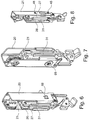
- Figures 6 and 7 are the in Figure 5 Components shown in an assembled state without the hanging component 25 shown.
- Figure 8 is the assembled state according to Figures 6 and 7 shown, wherein the outer housing 20, as well as the shaft 68, the sleeve 69 and the actuating element 23 are hidden and are therefore not shown.
- FIG. 9 to 11 Another variant of an actuating element is shown.
- the upper ramp 33 of the front connector 22 can also be designed differently.
- a further variant of an alternative height adjustment of the inner housing 21 relative to the outer housing 20 is indicated.
- the front connector 22 encloses 70 parts of the inner housing 21 with a U-shaped opening.
- FIG. 12 A further variant of an actuating arrangement 44 according to the invention with an alternative displacement element 31 is shown.
- Figure 13 shows a front view of a side frame adjustment device arranged on the drawer side part 18.
- ⁇ u> List of reference symbols ⁇ /u> 1 Furniture 32 Longitudinal axis 2nd drawer 33, 34 ramp 3rd Furniture body 33a, 33b Narrow side 4th Leadership resources 34a, 34b Narrow side 5, 6 Side wall 35 front 7 ground 36 back 8th Back wall 37, 38 Support section 9 Side frame adjustment device 39
- Component rear 40 Basic body 10, 11 Cross board 41-43 opening 12 Full extension 44 Actuator assembly 13, 14 Rail guide 45, 46 Guide element 15 Drawer front 47 Fastener 15a inside 48, 49 Side element 16 Drawer bottom 50 Middle section 17th Drawer side panel 51, 52 Executive body 17a, 18a The End 53 Through opening 18th Drawer side panel 54 Cylinder jacket 19th Back of the drawer 55 structure 20th Outer housing 56 Engaging element 21st Inner casing 57-60 Recess 22 Front connector 61, 62 Side panel 23 Actuator 63, 64 inside 24th Actuator 65, 66 Recess 25
Landscapes
- Drawers Of Furniture (AREA)
Applications Claiming Priority (1)
| Application Number | Priority Date | Filing Date | Title |
|---|---|---|---|
| DE202018107040.1U DE202018107040U1 (de) | 2018-12-10 | 2018-12-10 | Seitenzargenverstellvorrichtung zur seitlichen Verstellung einer Schubladenfront relativ zu einer Seitenzarge |
Publications (2)
| Publication Number | Publication Date |
|---|---|
| EP3666124A1 true EP3666124A1 (fr) | 2020-06-17 |
| EP3666124B1 EP3666124B1 (fr) | 2022-03-09 |
Family
ID=68344751
Family Applications (1)
| Application Number | Title | Priority Date | Filing Date |
|---|---|---|---|
| EP19205380.9A Active EP3666124B1 (fr) | 2018-12-10 | 2019-10-25 | Dispositif de réglage de châssis latéral destiné au réglage latéral d'un avant de tiroir par rapport à un châssis latéral |
Country Status (2)
| Country | Link |
|---|---|
| EP (1) | EP3666124B1 (fr) |
| DE (1) | DE202018107040U1 (fr) |
Families Citing this family (1)
| Publication number | Priority date | Publication date | Assignee | Title |
|---|---|---|---|---|
| DE102022208433A1 (de) * | 2022-08-12 | 2024-02-15 | Blanco Gmbh + Co Kg | Montagevorrichtung, Abdeckungssystem und Ausziehsystem |
Citations (4)
| Publication number | Priority date | Publication date | Assignee | Title |
|---|---|---|---|---|
| US20020125384A1 (en) * | 2001-03-09 | 2002-09-12 | Compagnucci - S.P.A. | Door support bracket provided with adjustment mechanism |
| CN201810622U (zh) * | 2010-09-04 | 2011-04-27 | 广东星徽金属制品有限公司 | 抽屉面板连接装置 |
| CN105661962A (zh) * | 2016-03-26 | 2016-06-15 | 佛山市顺德区新昊玮五金制品有限公司 | 抽屉侧板与面板的连接结构 |
| CN105708193A (zh) * | 2016-04-01 | 2016-06-29 | 伍志勇 | 一种用于家具抽屉前面板的可调节限位机构 |
Family Cites Families (2)
| Publication number | Priority date | Publication date | Assignee | Title |
|---|---|---|---|---|
| AT511538B1 (de) * | 2011-05-24 | 2013-06-15 | Blum Gmbh Julius | Befestigungsvorrichtung zum befestigen einer frontblende an einer schublade |
| DE202012003125U1 (de) * | 2012-02-20 | 2013-06-13 | Bulthaup Gmbh & Co. Kg | Auszug |
-
2018
- 2018-12-10 DE DE202018107040.1U patent/DE202018107040U1/de not_active Expired - Lifetime
-
2019
- 2019-10-25 EP EP19205380.9A patent/EP3666124B1/fr active Active
Patent Citations (4)
| Publication number | Priority date | Publication date | Assignee | Title |
|---|---|---|---|---|
| US20020125384A1 (en) * | 2001-03-09 | 2002-09-12 | Compagnucci - S.P.A. | Door support bracket provided with adjustment mechanism |
| CN201810622U (zh) * | 2010-09-04 | 2011-04-27 | 广东星徽金属制品有限公司 | 抽屉面板连接装置 |
| CN105661962A (zh) * | 2016-03-26 | 2016-06-15 | 佛山市顺德区新昊玮五金制品有限公司 | 抽屉侧板与面板的连接结构 |
| CN105708193A (zh) * | 2016-04-01 | 2016-06-29 | 伍志勇 | 一种用于家具抽屉前面板的可调节限位机构 |
Also Published As
| Publication number | Publication date |
|---|---|
| DE202018107040U1 (de) | 2020-03-13 |
| EP3666124B1 (fr) | 2022-03-09 |
Similar Documents
| Publication | Publication Date | Title |
|---|---|---|
| EP3612700B1 (fr) | Paroi de meuble avec un clapet et un corps de meuble et meuble avec une telle paroi de meuble | |
| AT510781B1 (de) | Möbelbeschlag zur frontblendenbefestigung | |
| EP3556978A1 (fr) | Dispositif de déplacement d'une partie de meuble logée sur une partie d'un meuble | |
| EP3988753B1 (fr) | Entraînement pour meuble | |
| EP3666126B1 (fr) | Dispositif de raccordement de tiroir pour raccorder une facade à une partie latérale | |
| EP1984590B1 (fr) | Dispositif de fixation serrable | |
| WO2016156049A1 (fr) | Châssis, notamment châssis latéral pour un tiroir | |
| AT14999U1 (de) | Band für eine Tür oder ein Fenster | |
| DE102007029557A9 (de) | Führungsvorrichtung für einen Schiebeflügel | |
| EP2747599B1 (fr) | Dispositif pour raccorder une façade à un châssis | |
| EP3082511B1 (fr) | Unité de montage de façade de tiroir | |
| EP3401479B1 (fr) | Ferrure d'abattant superieure pour un meuble | |
| EP3666124A1 (fr) | Dispositif de réglage de châssis latéral destiné au réglage latéral d'un avant de tiroir par rapport à un châssis latéral | |
| DE202011104559U1 (de) | Vorrichtung mit einer Anbringeinrichtung zur lösbaren Verbindung eines Frontteils einer Schublade mit einer Profilleiste sowie Möbel | |
| AT500268A1 (de) | Schneidemaschine für lebensmittel | |
| EP3666121B1 (fr) | Dispositif de raccordement de l'avant de tiroir et tiroir | |
| AT520767B1 (de) | Anordnung aus einem Auflagesteg für einen Schubladenboden und einer Haltevorrichtung | |
| EP3666122B1 (fr) | Dispositif de réglage de tiroir pour régler un connecteur avant | |
| EP3727091B1 (fr) | Arrangement comprenant une tringle et un element mural d'un tiroir | |
| DE20120238U1 (de) | Montageplatte zur verstellbaren Halterung von Möbelscharnieren am Korpus von Möbelstücken | |
| EP3666125B1 (fr) | Dispositif de réglage de tiroir permettant de régler un raccord avant d'une paroi latérale de tiroir | |
| AT511479B1 (de) | Biegewerkzeug und biegewerkzeuganordnung | |
| EP3797646B1 (fr) | Dispositif de raccordement permettant de raccorder les parois de tiroir, paroi de tiroir et meuble | |
| AT408058B (de) | Ausziehvorrichtung für hochschränke | |
| DE102011000196A1 (de) | Befestigungsvorrichtung |
Legal Events
| Date | Code | Title | Description |
|---|---|---|---|
| PUAI | Public reference made under article 153(3) epc to a published international application that has entered the european phase |
Free format text: ORIGINAL CODE: 0009012 |
|
| STAA | Information on the status of an ep patent application or granted ep patent |
Free format text: STATUS: THE APPLICATION HAS BEEN PUBLISHED |
|
| AK | Designated contracting states |
Kind code of ref document: A1 Designated state(s): AL AT BE BG CH CY CZ DE DK EE ES FI FR GB GR HR HU IE IS IT LI LT LU LV MC MK MT NL NO PL PT RO RS SE SI SK SM TR |
|
| AX | Request for extension of the european patent |
Extension state: BA ME |
|
| STAA | Information on the status of an ep patent application or granted ep patent |
Free format text: STATUS: REQUEST FOR EXAMINATION WAS MADE |
|
| 17P | Request for examination filed |
Effective date: 20201214 |
|
| RBV | Designated contracting states (corrected) |
Designated state(s): AL AT BE BG CH CY CZ DE DK EE ES FI FR GB GR HR HU IE IS IT LI LT LU LV MC MK MT NL NO PL PT RO RS SE SI SK SM TR |
|
| GRAP | Despatch of communication of intention to grant a patent |
Free format text: ORIGINAL CODE: EPIDOSNIGR1 |
|
| STAA | Information on the status of an ep patent application or granted ep patent |
Free format text: STATUS: GRANT OF PATENT IS INTENDED |
|
| GRAJ | Information related to disapproval of communication of intention to grant by the applicant or resumption of examination proceedings by the epo deleted |
Free format text: ORIGINAL CODE: EPIDOSDIGR1 |
|
| STAA | Information on the status of an ep patent application or granted ep patent |
Free format text: STATUS: REQUEST FOR EXAMINATION WAS MADE |
|
| INTG | Intention to grant announced |
Effective date: 20210618 |
|
| INTC | Intention to grant announced (deleted) | ||
| STAA | Information on the status of an ep patent application or granted ep patent |
Free format text: STATUS: EXAMINATION IS IN PROGRESS |
|
| GRAP | Despatch of communication of intention to grant a patent |
Free format text: ORIGINAL CODE: EPIDOSNIGR1 |
|
| STAA | Information on the status of an ep patent application or granted ep patent |
Free format text: STATUS: GRANT OF PATENT IS INTENDED |
|
| 17Q | First examination report despatched |
Effective date: 20210922 |
|
| INTG | Intention to grant announced |
Effective date: 20211018 |
|
| GRAS | Grant fee paid |
Free format text: ORIGINAL CODE: EPIDOSNIGR3 |
|
| GRAA | (expected) grant |
Free format text: ORIGINAL CODE: 0009210 |
|
| STAA | Information on the status of an ep patent application or granted ep patent |
Free format text: STATUS: THE PATENT HAS BEEN GRANTED |
|
| AK | Designated contracting states |
Kind code of ref document: B1 Designated state(s): AL AT BE BG CH CY CZ DE DK EE ES FI FR GB GR HR HU IE IS IT LI LT LU LV MC MK MT NL NO PL PT RO RS SE SI SK SM TR |
|
| REG | Reference to a national code |
Ref country code: CH Ref legal event code: EP Ref country code: AT Ref legal event code: REF Ref document number: 1473438 Country of ref document: AT Kind code of ref document: T Effective date: 20220315 |
|
| REG | Reference to a national code |
Ref country code: DE Ref legal event code: R096 Ref document number: 502019003637 Country of ref document: DE |
|
| REG | Reference to a national code |
Ref country code: IE Ref legal event code: FG4D Free format text: LANGUAGE OF EP DOCUMENT: GERMAN |
|
| REG | Reference to a national code |
Ref country code: LT Ref legal event code: MG9D |
|
| REG | Reference to a national code |
Ref country code: NL Ref legal event code: MP Effective date: 20220309 |
|
| PG25 | Lapsed in a contracting state [announced via postgrant information from national office to epo] |
Ref country code: SE Free format text: LAPSE BECAUSE OF FAILURE TO SUBMIT A TRANSLATION OF THE DESCRIPTION OR TO PAY THE FEE WITHIN THE PRESCRIBED TIME-LIMIT Effective date: 20220309 Ref country code: RS Free format text: LAPSE BECAUSE OF FAILURE TO SUBMIT A TRANSLATION OF THE DESCRIPTION OR TO PAY THE FEE WITHIN THE PRESCRIBED TIME-LIMIT Effective date: 20220309 Ref country code: NO Free format text: LAPSE BECAUSE OF FAILURE TO SUBMIT A TRANSLATION OF THE DESCRIPTION OR TO PAY THE FEE WITHIN THE PRESCRIBED TIME-LIMIT Effective date: 20220609 Ref country code: LT Free format text: LAPSE BECAUSE OF FAILURE TO SUBMIT A TRANSLATION OF THE DESCRIPTION OR TO PAY THE FEE WITHIN THE PRESCRIBED TIME-LIMIT Effective date: 20220309 Ref country code: HR Free format text: LAPSE BECAUSE OF FAILURE TO SUBMIT A TRANSLATION OF THE DESCRIPTION OR TO PAY THE FEE WITHIN THE PRESCRIBED TIME-LIMIT Effective date: 20220309 Ref country code: BG Free format text: LAPSE BECAUSE OF FAILURE TO SUBMIT A TRANSLATION OF THE DESCRIPTION OR TO PAY THE FEE WITHIN THE PRESCRIBED TIME-LIMIT Effective date: 20220609 |
|
| PG25 | Lapsed in a contracting state [announced via postgrant information from national office to epo] |
Ref country code: LV Free format text: LAPSE BECAUSE OF FAILURE TO SUBMIT A TRANSLATION OF THE DESCRIPTION OR TO PAY THE FEE WITHIN THE PRESCRIBED TIME-LIMIT Effective date: 20220309 Ref country code: GR Free format text: LAPSE BECAUSE OF FAILURE TO SUBMIT A TRANSLATION OF THE DESCRIPTION OR TO PAY THE FEE WITHIN THE PRESCRIBED TIME-LIMIT Effective date: 20220610 Ref country code: FI Free format text: LAPSE BECAUSE OF FAILURE TO SUBMIT A TRANSLATION OF THE DESCRIPTION OR TO PAY THE FEE WITHIN THE PRESCRIBED TIME-LIMIT Effective date: 20220309 |
|
| PG25 | Lapsed in a contracting state [announced via postgrant information from national office to epo] |
Ref country code: NL Free format text: LAPSE BECAUSE OF FAILURE TO SUBMIT A TRANSLATION OF THE DESCRIPTION OR TO PAY THE FEE WITHIN THE PRESCRIBED TIME-LIMIT Effective date: 20220309 |
|
| PG25 | Lapsed in a contracting state [announced via postgrant information from national office to epo] |
Ref country code: SM Free format text: LAPSE BECAUSE OF FAILURE TO SUBMIT A TRANSLATION OF THE DESCRIPTION OR TO PAY THE FEE WITHIN THE PRESCRIBED TIME-LIMIT Effective date: 20220309 Ref country code: SK Free format text: LAPSE BECAUSE OF FAILURE TO SUBMIT A TRANSLATION OF THE DESCRIPTION OR TO PAY THE FEE WITHIN THE PRESCRIBED TIME-LIMIT Effective date: 20220309 Ref country code: RO Free format text: LAPSE BECAUSE OF FAILURE TO SUBMIT A TRANSLATION OF THE DESCRIPTION OR TO PAY THE FEE WITHIN THE PRESCRIBED TIME-LIMIT Effective date: 20220309 Ref country code: PT Free format text: LAPSE BECAUSE OF FAILURE TO SUBMIT A TRANSLATION OF THE DESCRIPTION OR TO PAY THE FEE WITHIN THE PRESCRIBED TIME-LIMIT Effective date: 20220711 Ref country code: ES Free format text: LAPSE BECAUSE OF FAILURE TO SUBMIT A TRANSLATION OF THE DESCRIPTION OR TO PAY THE FEE WITHIN THE PRESCRIBED TIME-LIMIT Effective date: 20220309 Ref country code: EE Free format text: LAPSE BECAUSE OF FAILURE TO SUBMIT A TRANSLATION OF THE DESCRIPTION OR TO PAY THE FEE WITHIN THE PRESCRIBED TIME-LIMIT Effective date: 20220309 Ref country code: CZ Free format text: LAPSE BECAUSE OF FAILURE TO SUBMIT A TRANSLATION OF THE DESCRIPTION OR TO PAY THE FEE WITHIN THE PRESCRIBED TIME-LIMIT Effective date: 20220309 |
|
| PG25 | Lapsed in a contracting state [announced via postgrant information from national office to epo] |
Ref country code: PL Free format text: LAPSE BECAUSE OF FAILURE TO SUBMIT A TRANSLATION OF THE DESCRIPTION OR TO PAY THE FEE WITHIN THE PRESCRIBED TIME-LIMIT Effective date: 20220309 Ref country code: IS Free format text: LAPSE BECAUSE OF FAILURE TO SUBMIT A TRANSLATION OF THE DESCRIPTION OR TO PAY THE FEE WITHIN THE PRESCRIBED TIME-LIMIT Effective date: 20220709 Ref country code: AL Free format text: LAPSE BECAUSE OF FAILURE TO SUBMIT A TRANSLATION OF THE DESCRIPTION OR TO PAY THE FEE WITHIN THE PRESCRIBED TIME-LIMIT Effective date: 20220309 |
|
| REG | Reference to a national code |
Ref country code: DE Ref legal event code: R097 Ref document number: 502019003637 Country of ref document: DE |
|
| PLBE | No opposition filed within time limit |
Free format text: ORIGINAL CODE: 0009261 |
|
| STAA | Information on the status of an ep patent application or granted ep patent |
Free format text: STATUS: NO OPPOSITION FILED WITHIN TIME LIMIT |
|
| PG25 | Lapsed in a contracting state [announced via postgrant information from national office to epo] |
Ref country code: DK Free format text: LAPSE BECAUSE OF FAILURE TO SUBMIT A TRANSLATION OF THE DESCRIPTION OR TO PAY THE FEE WITHIN THE PRESCRIBED TIME-LIMIT Effective date: 20220309 |
|
| 26N | No opposition filed |
Effective date: 20221212 |
|
| PG25 | Lapsed in a contracting state [announced via postgrant information from national office to epo] |
Ref country code: SI Free format text: LAPSE BECAUSE OF FAILURE TO SUBMIT A TRANSLATION OF THE DESCRIPTION OR TO PAY THE FEE WITHIN THE PRESCRIBED TIME-LIMIT Effective date: 20220309 |
|
| PG25 | Lapsed in a contracting state [announced via postgrant information from national office to epo] |
Ref country code: MC Free format text: LAPSE BECAUSE OF FAILURE TO SUBMIT A TRANSLATION OF THE DESCRIPTION OR TO PAY THE FEE WITHIN THE PRESCRIBED TIME-LIMIT Effective date: 20220309 |
|
| REG | Reference to a national code |
Ref country code: CH Ref legal event code: PL |
|
| REG | Reference to a national code |
Ref country code: BE Ref legal event code: MM Effective date: 20221031 |
|
| PG25 | Lapsed in a contracting state [announced via postgrant information from national office to epo] |
Ref country code: LU Free format text: LAPSE BECAUSE OF NON-PAYMENT OF DUE FEES Effective date: 20221025 |
|
| PG25 | Lapsed in a contracting state [announced via postgrant information from national office to epo] |
Ref country code: LI Free format text: LAPSE BECAUSE OF NON-PAYMENT OF DUE FEES Effective date: 20221031 Ref country code: FR Free format text: LAPSE BECAUSE OF NON-PAYMENT OF DUE FEES Effective date: 20221031 Ref country code: CH Free format text: LAPSE BECAUSE OF NON-PAYMENT OF DUE FEES Effective date: 20221031 |
|
| PG25 | Lapsed in a contracting state [announced via postgrant information from national office to epo] |
Ref country code: BE Free format text: LAPSE BECAUSE OF NON-PAYMENT OF DUE FEES Effective date: 20221031 |
|
| PG25 | Lapsed in a contracting state [announced via postgrant information from national office to epo] |
Ref country code: IE Free format text: LAPSE BECAUSE OF NON-PAYMENT OF DUE FEES Effective date: 20221025 |
|
| PG25 | Lapsed in a contracting state [announced via postgrant information from national office to epo] |
Ref country code: HU Free format text: LAPSE BECAUSE OF FAILURE TO SUBMIT A TRANSLATION OF THE DESCRIPTION OR TO PAY THE FEE WITHIN THE PRESCRIBED TIME-LIMIT; INVALID AB INITIO Effective date: 20191025 |
|
| PG25 | Lapsed in a contracting state [announced via postgrant information from national office to epo] |
Ref country code: CY Free format text: LAPSE BECAUSE OF FAILURE TO SUBMIT A TRANSLATION OF THE DESCRIPTION OR TO PAY THE FEE WITHIN THE PRESCRIBED TIME-LIMIT Effective date: 20220309 |
|
| PG25 | Lapsed in a contracting state [announced via postgrant information from national office to epo] |
Ref country code: MK Free format text: LAPSE BECAUSE OF FAILURE TO SUBMIT A TRANSLATION OF THE DESCRIPTION OR TO PAY THE FEE WITHIN THE PRESCRIBED TIME-LIMIT Effective date: 20220309 |
|
| GBPC | Gb: european patent ceased through non-payment of renewal fee |
Effective date: 20231025 |
|
| PG25 | Lapsed in a contracting state [announced via postgrant information from national office to epo] |
Ref country code: GB Free format text: LAPSE BECAUSE OF NON-PAYMENT OF DUE FEES Effective date: 20231025 |
|
| PG25 | Lapsed in a contracting state [announced via postgrant information from national office to epo] |
Ref country code: GB Free format text: LAPSE BECAUSE OF NON-PAYMENT OF DUE FEES Effective date: 20231025 |
|
| PG25 | Lapsed in a contracting state [announced via postgrant information from national office to epo] |
Ref country code: MT Free format text: LAPSE BECAUSE OF FAILURE TO SUBMIT A TRANSLATION OF THE DESCRIPTION OR TO PAY THE FEE WITHIN THE PRESCRIBED TIME-LIMIT Effective date: 20220309 |
|
| REG | Reference to a national code |
Ref country code: DE Ref legal event code: R082 Ref document number: 502019003637 Country of ref document: DE Representative=s name: RAVENSPAT PATENTANWAELTE PARTNERSCHAFT MBB, DE |
|
| PG25 | Lapsed in a contracting state [announced via postgrant information from national office to epo] |
Ref country code: TR Free format text: LAPSE BECAUSE OF FAILURE TO SUBMIT A TRANSLATION OF THE DESCRIPTION OR TO PAY THE FEE WITHIN THE PRESCRIBED TIME-LIMIT Effective date: 20220309 |
|
| PGFP | Annual fee paid to national office [announced via postgrant information from national office to epo] |
Ref country code: DE Payment date: 20251024 Year of fee payment: 7 |
|
| PGFP | Annual fee paid to national office [announced via postgrant information from national office to epo] |
Ref country code: AT Payment date: 20251027 Year of fee payment: 7 |
|
| PGFP | Annual fee paid to national office [announced via postgrant information from national office to epo] |
Ref country code: IT Payment date: 20251015 Year of fee payment: 7 |