EP2748104B1 - Dispositif de production de vide destiné à des installations de traitement de récipients et procédé de commande d'un dispositif de production de vide - Google Patents
Dispositif de production de vide destiné à des installations de traitement de récipients et procédé de commande d'un dispositif de production de vide Download PDFInfo
- Publication number
- EP2748104B1 EP2748104B1 EP12743680.6A EP12743680A EP2748104B1 EP 2748104 B1 EP2748104 B1 EP 2748104B1 EP 12743680 A EP12743680 A EP 12743680A EP 2748104 B1 EP2748104 B1 EP 2748104B1
- Authority
- EP
- European Patent Office
- Prior art keywords
- vacuum
- capacity
- pumps
- vacuum pumps
- vacuum device
- Prior art date
- Legal status (The legal status is an assumption and is not a legal conclusion. Google has not performed a legal analysis and makes no representation as to the accuracy of the status listed.)
- Active
Links
Images

Classifications
-
- F—MECHANICAL ENGINEERING; LIGHTING; HEATING; WEAPONS; BLASTING
- F04—POSITIVE - DISPLACEMENT MACHINES FOR LIQUIDS; PUMPS FOR LIQUIDS OR ELASTIC FLUIDS
- F04B—POSITIVE-DISPLACEMENT MACHINES FOR LIQUIDS; PUMPS
- F04B37/00—Pumps having pertinent characteristics not provided for in, or of interest apart from, groups F04B25/00 - F04B35/00
- F04B37/10—Pumps having pertinent characteristics not provided for in, or of interest apart from, groups F04B25/00 - F04B35/00 for special use
- F04B37/14—Pumps having pertinent characteristics not provided for in, or of interest apart from, groups F04B25/00 - F04B35/00 for special use to obtain high vacuum
-
- B—PERFORMING OPERATIONS; TRANSPORTING
- B67—OPENING, CLOSING OR CLEANING BOTTLES, JARS OR SIMILAR CONTAINERS; LIQUID HANDLING
- B67C—CLEANING, FILLING WITH LIQUIDS OR SEMILIQUIDS, OR EMPTYING, OF BOTTLES, JARS, CANS, CASKS, BARRELS, OR SIMILAR CONTAINERS, NOT OTHERWISE PROVIDED FOR; FUNNELS
- B67C3/00—Bottling liquids or semiliquids; Filling jars or cans with liquids or semiliquids using bottling or like apparatus; Filling casks or barrels with liquids or semiliquids
- B67C3/02—Bottling liquids or semiliquids; Filling jars or cans with liquids or semiliquids using bottling or like apparatus
-
- B—PERFORMING OPERATIONS; TRANSPORTING
- B67—OPENING, CLOSING OR CLEANING BOTTLES, JARS OR SIMILAR CONTAINERS; LIQUID HANDLING
- B67C—CLEANING, FILLING WITH LIQUIDS OR SEMILIQUIDS, OR EMPTYING, OF BOTTLES, JARS, CANS, CASKS, BARRELS, OR SIMILAR CONTAINERS, NOT OTHERWISE PROVIDED FOR; FUNNELS
- B67C7/00—Concurrent cleaning, filling, and closing of bottles; Processes or devices for at least two of these operations
- B67C7/0073—Sterilising, aseptic filling and closing
-
- F—MECHANICAL ENGINEERING; LIGHTING; HEATING; WEAPONS; BLASTING
- F04—POSITIVE - DISPLACEMENT MACHINES FOR LIQUIDS; PUMPS FOR LIQUIDS OR ELASTIC FLUIDS
- F04B—POSITIVE-DISPLACEMENT MACHINES FOR LIQUIDS; PUMPS
- F04B41/00—Pumping installations or systems specially adapted for elastic fluids
- F04B41/06—Combinations of two or more pumps
-
- F—MECHANICAL ENGINEERING; LIGHTING; HEATING; WEAPONS; BLASTING
- F04—POSITIVE - DISPLACEMENT MACHINES FOR LIQUIDS; PUMPS FOR LIQUIDS OR ELASTIC FLUIDS
- F04B—POSITIVE-DISPLACEMENT MACHINES FOR LIQUIDS; PUMPS
- F04B49/00—Control, e.g. of pump delivery, or pump pressure of, or safety measures for, machines, pumps, or pumping installations, not otherwise provided for, or of interest apart from, groups F04B1/00 - F04B47/00
- F04B49/06—Control using electricity
-
- F—MECHANICAL ENGINEERING; LIGHTING; HEATING; WEAPONS; BLASTING
- F04—POSITIVE - DISPLACEMENT MACHINES FOR LIQUIDS; PUMPS FOR LIQUIDS OR ELASTIC FLUIDS
- F04B—POSITIVE-DISPLACEMENT MACHINES FOR LIQUIDS; PUMPS
- F04B49/00—Control, e.g. of pump delivery, or pump pressure of, or safety measures for, machines, pumps, or pumping installations, not otherwise provided for, or of interest apart from, groups F04B1/00 - F04B47/00
- F04B49/20—Control, e.g. of pump delivery, or pump pressure of, or safety measures for, machines, pumps, or pumping installations, not otherwise provided for, or of interest apart from, groups F04B1/00 - F04B47/00 by changing the driving speed
-
- B—PERFORMING OPERATIONS; TRANSPORTING
- B67—OPENING, CLOSING OR CLEANING BOTTLES, JARS OR SIMILAR CONTAINERS; LIQUID HANDLING
- B67C—CLEANING, FILLING WITH LIQUIDS OR SEMILIQUIDS, OR EMPTYING, OF BOTTLES, JARS, CANS, CASKS, BARRELS, OR SIMILAR CONTAINERS, NOT OTHERWISE PROVIDED FOR; FUNNELS
- B67C3/00—Bottling liquids or semiliquids; Filling jars or cans with liquids or semiliquids using bottling or like apparatus; Filling casks or barrels with liquids or semiliquids
- B67C3/02—Bottling liquids or semiliquids; Filling jars or cans with liquids or semiliquids using bottling or like apparatus
- B67C3/22—Details
- B67C3/26—Filling-heads; Means for engaging filling-heads with bottle necks
- B67C2003/2688—Means for filling containers in defined atmospheric conditions
Definitions
- the invention relates to a vacuum device according to the preamble of patent claim 1, to a system for treating containers according to the preamble 7 and to a method for controlling a vacuum device of the claim according to the preamble of claim 8.
- the preamble of claims 1, 7 and 8 is for example from the EP 1 595 794 A1 known.
- vacuum or vacuum is required and used to remove ambient air and associated with the oxygen in the ambient air from the containers to be filled, in one of the actual filling phase preceding single or multi-stage pre-treatment phase.
- the disadvantage is u.a. an increased effort for storage and stockpiling of different vacuum pumps and their spare parts, associated increased costs and the fact that a change in the vacuum and suction power of the vacuum device in question only to a limited extent and then only possible that in certain operating conditions only an inadequate efficiency for the single vacuum pump is accepted.
- the object of the invention is to provide a vacuum device which avoids the aforementioned disadvantages and allows for high reliability adjustment of the vacuum device provided or ready to be provided vacuum or suction in a wide range and while maintaining the best possible efficiency.
- a vacuum device according to the patent claim 1 is formed.
- a system for treating containers is the subject of claim 7.
- a method for controlling a vacuum device is the subject of claim 8.
- the vacuum device consists of at least two vacuum pumps designed for parallel operation, preferably of more than two vacuum pumps designed for parallel operation, these vacuum pumps preferably being of identical construction and power.
- Another aspect of the invention is that the total vacuum or suction power of the vacuum device is controlled by the speed and the number of activated vacuum pumps.
- the invention offers the possibility to convert existing vacuum devices accordingly.
- “Bulk performance” in the sense of the invention means e.g. Capacity of the container filling machine per unit of time measured in liters.
- Container are in the context of the invention in particular cans, bottles, tubes, pouches, each made of metal, glass and / or plastic, but also other packaging materials that are suitable for filling liquid or viscous products.
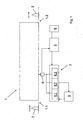
- FIG. 1 1 is a plant for treating containers 2, for example in the form of bottles.
- the plant 1 comprises at least one device or machine, for example a filling machine, in which the containers 2 and / or device areas are subjected to a vacuum or to a negative pressure, for example with a negative pressure in the range from 80 mbar to 100 mbar.
- the containers 2 are fed to the system 1 at a container inlet 1.1 and discharged from the system 1 at a container outlet 1.2.
- a central vacuum device 3 is provided for the system 1, which has a multiplicity of electrically operated vacuum pumps 4.1-4.3.
- the vacuum device 3 has a total of three vacuum pumps 4.1 - 4.3, the vacuum or suction power can be individually controlled within certain limits by changing the pump speed or regulated.
- the electrical control of the drive motor of the respective vacuum pump 4.1 - 4.3 is frequency-controlled via a frequency control device, for example in a frequency range between 40 Hz and 60 Hz.
- a control and regulating electronics or a machine control referred to, for example, is formed by the process computer of Appendix 1 or provided in addition to this process computer and, among other things, depending on process parameters in the manner described in more detail below, the circuit and control or regulation the vacuum pump 4.1 - 4.3 takes place.
- the process parameters can for example be retrievable from a memory of the control and regulating electronics and / or be input via an input 6 in the control electronics.
- the containers for example, before the actual filling one or more times applied with vacuum and then with an inert gas, such as CO2 gas, rinsed, it may be in the process parameters to product-specific parameters, the container size, the filling temperature, etc. act.
- an inert gas such as CO2 gas
- the required number of pumps is for example tabulated and entered or read at the beginning of production in the machine control 5 for a special treatment method and for a temperature for the closed circuit of the vacuum pumps 4.1 - 4.3, so that with this number of pumps (start condition) the production Appendix 1 can be started.
- the suction power of the vacuum pumps 4.1 - 4.3 is controlled or regulated by their speed. In this case, it is necessary, depending on the type of pump used, to set the speed of the vacuum pump 4.1-4.3 so that it makes economic sense, i. can be operated with the best possible efficiency.
- a pump characteristic can be determined for each type of pump, which reproduces the electrical connection power, ie the electrical power requirement as a function of the vacuum or suction power .
- the electrical connection power ie the electrical power requirement as a function of the vacuum or suction power
- other parameters such as the barrier water temperature have a significant influence on the electrical power requirement of the respective vacuum pump 4.1 - 4.3, these are also taken into account in the pump characteristic or parameter-specific pump characteristics are determined.
- the pump characteristic preferably also taking into account the overall efficiency of the vacuum device 3 and the vacuum-leading portion of the system 1, which is in the FIG. 2 represented overall characteristic curve 7 formed at a given, from the Vacuum device 3 generated constant negative pressure, ie in the illustrated embodiment at a negative pressure of 80 mbar the electrical power requirement in kW as a function of the suction power in m 3 / h reproduces.
- An essential part of the overall characteristic curve 7 are the switching points specified there with SP1 and SP2, at which switching the number of vacuum pumps 4.1-4.3 to a higher or lower number of vacuum pumps, for example switching from a vacuum pump to two parallel-operated vacuum pumps at the switching point SP1 or switching from two parallel operated vacuum pumps to three parallel operated vacuum pumps at the switching point SP2 and vice versa.
- the switching by the machine control 5 for example, the electric power supplied to the vacuum device, which is monitored by the machine control.
- the operating point is a possible operating point in the operation of a single vacuum pump 4.1-4.3, wherein also for this operating point of a single vacuum pump suction power and associated power consumption are known.
- the operating point 7.1 suction power of the power requirement of a single vacuum pump significantly above the power demand of two parallel operated vacuum pumps.
- the pumps are operated in the different operating states with different frequencies and thus with different pump speeds, namely in the operating state with only one activated vacuum pump 4.1 - 4.3 with a frequency between 40 and 58 Hz, in the operating state with two activated vacuum pumps 4.1 - 4.3 with a frequency between 40 and 52 Hz and in the operating state with three activated pumps with a frequency between 40 and 60 Hz.
- the in the FIG. 2 reproduced overall characteristic takes into account a sealing water temperature of the vacuum pump 4.1 - 4.3, for example, 25 ° C. If the sealing water temperature has a greater influence on the pump characteristic or on the efficiency of the vacuum pumps 4.1-4.3, then different overall characteristic curves 7 result for each barrier water temperature, which are then taken into account for the control and regulation of the vacuum pumps 4.1-4.3 during the ongoing process.
- the barrier water temperature is preferably continuously measured during operation of the system 1 and transmitted to the machine control 5, the machine controller 5 depending on the measured barrier water temperature, the respective associated overall characteristic curve 7 is used to control or regulate the system.
- the overall characteristic curve 7 shown as an example also assumes that the vacuum pumps 4.1-4.3 operating in parallel are each operated at the same frequency of the supply voltage. Although this is an easy to implement solution, operation of the parallel vacuum pumps is 4.1 - 4.3 basically not necessarily with the same frequency of the supply voltage. In the context of the present invention, it is likewise provided that the individual, parallel-operated vacuum pumps 4.1-4.3 are also operated with different mains frequencies, which opens up the possibility of increasing the efficiency of the overall system, at least for some vacuum powers.
- a predetermined desired negative pressure for example the negative pressure of 80 mbar - 100 mbar, which is then identical to the negative pressure at the suction side of the activated vacuum pumps 4.1 - 4.3.
- a pressure sensor 8 in a vacuum line between the vacuum device 3 and the system 1 play.
- At least the vacuum power of one of the activated vacuum pumps 4.1-4.3 is changed via appropriate adjustment of the frequency and thus the pump speed via the machine controller 5 so that the negative pressure provided by the vacuum device 3 is the target negative pressure equivalent.
- the machine control 5 switches according to the overall characteristic curve 7 to the next higher number of parallel-operated vacuum pumps 4.1-4.3. Conversely, if a reduction of the suction power of the vacuum unit 3 and thus a reduction of the pump speed is required, then the machine control 5 switches to the next lower number of activated vacuum pumps 4.1 - 4.3 when reaching the switching point SP1 or SP2.
- FIG. 1 a common for all vacuum pumps 4.1 - 4.3 of the vacuum device 3 means for providing and / or Preparation of sealing water, which is part of the vacuum pump 4.1 - 4.3 water circuit and includes a device for cooling the sealing water and connections for venting, for supplying fresh water and for discharging wastewater.
- both at the beginning of the process and during the ongoing process of the machine controller 5 always those vacuum 4.1 - 4.3 preferably activated, currently have the lowest operating times, so that a uniform use of all vacuum pumps 4.1 - 4.3 takes place and for all vacuum pumps the respective Maintenance is due at the same time.
- the vacuum pumps 4.1-4.3 to be activated are each selected so that the maintenance for a subset of the vacuum pumps 4.1-4.3 is then incurred, even if the plant 1 and / or its components must be maintained, so u.a. the number of production stoppages and / or operations for maintenance personnel and thus the associated costs are considerably reduced.
- vacuum pump 4.1 - 4.3 After a further operating method that vacuum pump 4.1 - 4.3 is blocked, in which, for example, due to their operating hours and / or their condition maintenance is mandatory.
- the operation of the vacuum device 3 is then carried out exclusively with the remaining, not locked vacuum pumps 4.1 - 4.3.
- the maintenance and / or repair of the locked vacuum pump are carried out during operation.
Landscapes
- Engineering & Computer Science (AREA)
- Mechanical Engineering (AREA)
- General Engineering & Computer Science (AREA)
- Compressors, Vaccum Pumps And Other Relevant Systems (AREA)
Claims (14)
- Dispositif de production de vide pour la génération de dépression dans des installations de traitement de récipients (2), en particulier dans des installations de remplissage de récipients (2) avec un produit de remplissage liquide, avec une source de vide, dont la capacité de vide et/ou d'aspiration peut être commandée et/ou régulée, la source de vide du dispositif de production de vide (3) étant formée par au moins deux pompes à vide (4.1-4.3) entraînées électriquement, réalisées pour un fonctionnement parallèle, et en ce que la capacité de vide ou d'aspiration totale du dispositif de production de vide (3) peut être commandée par le nombre des pompes à vide (4.1-4.3) activées respectivement par une unité de commande et de régulation (5), caractérisé en ce que l'unité de commande et de régulation (5) est réalisée pour une commande et/ou une régulation de la capacité de vide ou d'aspiration des pompes à vide (4.1-4.3) et/ou pour l'activation et la désactivation des pompes à vide (4.1-4.3) en tenant compte d'une courbe caractéristique totale (7) du dispositif de production de vide (3) qui reproduit la puissance électrique requise pour une capacité de vide ou d'aspiration totale du dispositif de production de vide (3) pour l'entraînement des pompes à vide (4.1-4.3), et ce de préférence en tenant compte de courbes caractéristiques de pompe des pompes à vide (4.1-4.3) et/ou d'un rendement optimal résultant respectivement de la courbe caractéristique de pompe pour les pompes à vide (4.1-4.3), les courbes caractéristiques de pompe des pompes à vide (4.1-4.3) reproduisant leur capacité de vide et d'aspiration en fonction du besoin de puissance électrique.
- Dispositif de production de vide selon la revendication 1, caractérisé en ce que la capacité de vide ou d'aspiration de chaque pompe à vide (4.1-4.3) peut être commandée et régulée, de préférence par modification de la fréquence de la tension d'alimentation entraînant les pompes à vide (4.1-4.3), par exemple par une modification de la fréquence dans une plage de fréquences entre 40 et 60 Hz.
- Dispositif de production de vide selon la revendication 1 ou 2, caractérisé en ce que l'unité de commande et de régulation (5) est réalisée pour une commande et/ou une régulation de la capacité de vide ou d'aspiration totale du dispositif de production de vide (3) en fonction de paramètres de processus de l'installation (1) de traitement des récipients (2), les paramètres de processus tenant compte par exemple du type des procédés de traitement réalisés avec l'installation (1) et/ou des grandeurs de récipient et/ou des formes de récipient et/ou de la capacité de remplissage de l'installation (1) et/ou d'une machine de remplissage de récipient.
- Dispositif de production de vide selon l'une quelconque des revendications précédentes, caractérisé en ce que la courbe caractéristique totale (7) présente des points de commutation (SP1, SP2), sur lesquels la commutation du dispositif de production de vide (3) est effectuée d'un nombre de pompes à vide (4.1-4.3) activées à un nombre suivant plus élevé ou plus bas de pompes à vide (4.1-4.3) activées.
- Dispositif de production de vide selon l'une quelconque des revendications précédentes, caractérisé en ce que les pompes à vide (4.1-4.3) sont respectivement des pompes de même construction.
- Dispositif de production de vide selon l'une quelconque des revendications précédentes, caractérisé en ce que pour toutes les pompes à vide (4.1-4.3), un dispositif commun (9) est prévu pour la mise à disposition et/ou la préparation d'eau d'étanchéité.
- Installation de traitement de récipients (2), en particulier de remplissage de récipients (2) avec un produit de remplissage liquide, avec un dispositif de production de vide (3) pour une alimentation de récipients (2) et/ou des zones de l'installation (1) en un vide ou une dépression, caractérisée en ce que le dispositif de production de vide (3) est réalisé selon l'une quelconque des revendications précédentes.
- Procédé de commande d'un dispositif de production de vide (3) pour des installations (1) de traitement de récipients (2), en particulier pour des installations de remplissage de récipients (2) avec un produit de remplissage liquide, une capacité de vide ou d'aspiration totale du dispositif de production de vide (3) pouvant être commandée et/ou régulée, le dispositif de production de vide (3) présentant au moins deux pompes à vide (4.1-4.3) réalisées pour un fonctionnement parallèle, et, pour la commande et/ou la régulation de la capacité de vide ou d'aspiration totale du dispositif de production de vide (3), la capacité de vide ou d'aspiration des pompes à vide (4.1-4.3) étant commandée et/ou régulée et/ou le nombre des pompes à vide (4.1-4.3) activées étant modifié par activation et désactivation des pompes à vide (4.1-4.3), caractérisé en ce que la commande et/ou la régulation de la capacité de vide ou d'aspiration des pompes à vide (4.1-4.3) et/ou l'activation et la désactivation des pompes à vide (4.1-4.3) sont effectuées en tenant compte d'une courbe caractéristique totale (7) du dispositif de production de vide (3) qui reproduit la puissance électrique requise pour une capacité de vide ou d'aspiration totale du dispositif de production de vide (3) pour l'entraînement des pompes à vide (4.1-4.3), et ce de préférence en tenant compte de courbes caractéristiques de pompe des pompes à vide (4.1-4.3) et/ou d'un rendement optimal résultant respectivement de leur courbe caractéristique de pompe pour les pompes à vide (4.1-4.3), les courbes caractéristiques de pompe des pompes à vide (4.1-4.3) reproduisant leur capacité de vide et d'aspiration en fonction du besoin de puissance électrique.
- Procédé selon la revendication 8, caractérisé en ce que le nombre de pompes à vide (4.1-4.3) à activer est déterminé au début d'un procédé réalisé avec l'installation (1) de traitement des récipients (2) tout d'abord en tenant compte au moins du procédé de traitement de récipients et de la capacité de vide ou d'aspiration totale nécessaire à cet effet du dispositif de production de vide (3) et celles-ci sont activées.
- Procédé selon l'une quelconque des revendications 8 ou 9, caractérisé en ce que la commande et/ou la régulation de la capacité de vide ou d'aspiration totale du dispositif de production de vide (3) est effectuée en fonction de paramètres de processus de l'installation (1) de traitement des récipients (2), les paramètres de processus tenant compte par exemple du type des procédés de traitement réalisés avec l'installation (1) et/ou des grandeurs de récipient et/ou des formes de récipient et/ou de la capacité de remplissage de l'installation (1) et/ou d'une machine de remplissage de récipient.
- Procédé selon l'une quelconque des revendications 8 à 10, caractérisé en ce que la commutation du dispositif de production de vide (3) est effectuée d'un nombre de pompes à vide (4.1-4.3) activées à un nombre suivant plus élevé ou plus faible de pompes à vide (4.1-4.3) activées sur des points de commutation (SP1, SP2) de la courbe caractéristique totale (7).
- Procédé selon l'une quelconque des revendications 8 à 11, caractérisé en ce que les pompes à vide (4.1-4.3) qui présentent actuellement les plus faibles temps de fonctionnement sont activées pour atteindre les mêmes temps de fonctionnement ou sensiblement les mêmes temps de fonctionnement.
- Procédé selon l'une quelconque des revendications 8 à 12, caractérisé en ce que les pompes à vide (4.1-4.3) à activer sont sélectionnées respectivement de sorte que la maintenance pour une quantité partielle des pompes à vide (4.1-4.3) se présente si l'installation 1 ou des composants de cette installation doivent aussi être entretenus.
- Procédé selon l'une quelconque des revendications 8 à 13, caractérisé en ce que la maintenance et/ou la réparation d'une pompe à vide (4.1-4.3) est réalisée après son arrêt en cours de fonctionnement des pompes à vide (4.1-4.3) restantes de l'unité de production de vide (3).
Priority Applications (1)
| Application Number | Priority Date | Filing Date | Title |
|---|---|---|---|
| SI201230332T SI2748104T2 (sl) | 2011-08-25 | 2012-08-01 | Vakuumska priprava za postrojenja za obdelavo vsebnikov in postopek za krmiljenje vakuumske priprave |
Applications Claiming Priority (2)
| Application Number | Priority Date | Filing Date | Title |
|---|---|---|---|
| DE102011111188A DE102011111188A1 (de) | 2011-08-25 | 2011-08-25 | Vakuumeinrichtung für Anlagen zur Behandlung von Behältern, Anlage zur Behandlung von Behältern sowie Verfahren zur Steuerung einer Vakuumeirichtung |
| PCT/EP2012/003266 WO2013026522A1 (fr) | 2011-08-25 | 2012-08-01 | Dispositif de production de vide destiné à des installations de traitement de récipients et procédé de commande d'un dispositif de production de vide |
Publications (3)
| Publication Number | Publication Date |
|---|---|
| EP2748104A1 EP2748104A1 (fr) | 2014-07-02 |
| EP2748104B1 true EP2748104B1 (fr) | 2015-09-30 |
| EP2748104B2 EP2748104B2 (fr) | 2019-04-10 |
Family
ID=46634099
Family Applications (1)
| Application Number | Title | Priority Date | Filing Date |
|---|---|---|---|
| EP12743680.6A Active EP2748104B2 (fr) | 2011-08-25 | 2012-08-01 | Dispositif de production de vide destiné à des installations de traitement de récipients et procédé de commande d'un dispositif de production de vide |
Country Status (5)
| Country | Link |
|---|---|
| US (1) | US9599104B2 (fr) |
| EP (1) | EP2748104B2 (fr) |
| DE (1) | DE102011111188A1 (fr) |
| SI (1) | SI2748104T2 (fr) |
| WO (1) | WO2013026522A1 (fr) |
Families Citing this family (2)
| Publication number | Priority date | Publication date | Assignee | Title |
|---|---|---|---|---|
| ITPD20120028A1 (it) * | 2012-02-07 | 2013-08-08 | Mbf Spa | Macchina riempitrice di contenitori con liquidi, e procedimento di riempimento di contenitori, in particolare mediante detta macchina riempitrice |
| CN110454359A (zh) * | 2019-09-10 | 2019-11-15 | 浙江伟博化工科技有限公司 | 一种增塑剂节能型真空系统 |
Citations (15)
| Publication number | Priority date | Publication date | Assignee | Title |
|---|---|---|---|---|
| DE7441311U (de) | 1974-12-11 | 1976-07-01 | Siemens Ag, 1000 Berlin Und 8000 Muenchen | Verdichteranordnung |
| JPS59211782A (ja) | 1983-05-13 | 1984-11-30 | Mitsubishi Electric Corp | 並列圧縮式冷凍装置 |
| JPS60147586A (ja) | 1984-01-11 | 1985-08-03 | Hitachi Ltd | 圧縮機の制御方法 |
| US4589945A (en) | 1985-07-05 | 1986-05-20 | Xerox Corporation | Vacuum supply control for a three pad labelling head machine |
| DE19826169A1 (de) | 1998-06-13 | 1999-12-16 | Kaeser Kompressoren Gmbh | Elektronische Steuerung für Anlagen der Druckluft- und Vakuumerzeugung |
| DE19916478A1 (de) | 1999-04-13 | 2000-10-19 | Ruediger Haaga Gmbh | Verfahren zum Evakuieren eines Plasmasterilisations-Reaktors |
| DE19941456C1 (de) | 1999-08-31 | 2001-04-12 | Sasib Beverage Deutschland Gmb | Füllmaschine mit vakuumbeaufschlagbaren Füllorganen |
| DE10028290A1 (de) | 2000-06-07 | 2001-12-13 | Krones Ag | Verfahren und Vorrichtung zum Abfüllen von Flüssigkeiten, insbesondere sauerstoffempfindlichen Getränken in Flaschen oder dgl. |
| WO2002064174A1 (fr) | 2001-02-16 | 2002-08-22 | Steris Inc. | Decontamination en phase vapeur de recipients |
| US20030068233A1 (en) | 2001-10-09 | 2003-04-10 | Applied Materials, Inc. | Device and method for reducing vacuum pump energy consumption |
| DE10300734A1 (de) | 2003-01-11 | 2004-07-22 | Sig Technology Ltd. | Verfahren und Vorrichtung zur Plasmabehandlung von Werkstücken |
| EP1595794A1 (fr) | 2004-05-14 | 2005-11-16 | Felix Rudolf Bilz | Procédé et dispositif d'évacuation d'une chambre |
| US7480544B2 (en) | 2005-12-02 | 2009-01-20 | Wen-Cheng Huang | Operation method of energy-saving fluid transporting machineries in parallel array with constant pressure |
| DE202009016578U1 (de) | 2008-06-17 | 2010-03-25 | EREMA Engineering Recycling Maschinen und Anlagen Ges.m.b.H. | Anordnung zur Vorbehandlung von Polymermaterialien |
| US7955056B2 (en) | 2003-04-04 | 2011-06-07 | Atlas Copco Airpower, Naamloze Vennootschap | Method for controlling a compressed air installation comprising several compressors, control box applied thereby and compressed air installation applying this method |
Family Cites Families (11)
| Publication number | Priority date | Publication date | Assignee | Title |
|---|---|---|---|---|
| US3282306A (en) * | 1964-04-02 | 1966-11-01 | Pastemaster Inc | Process and apparatus for the charging of containers |
| US4713925A (en) * | 1985-04-01 | 1987-12-22 | Kafkis N H | Method and apparatus for filling a plurality of flexible pipette type vessels |
| US5176187A (en) * | 1989-06-27 | 1993-01-05 | Ashland Oil, Inc. | Flexible gas salvage containers and process for use |
| US5383499A (en) * | 1992-05-04 | 1995-01-24 | Earth Resources Corporation | System for removal of unknown, corrossive, or potentially hazardous gases from a gas container |
| DE4314054C1 (de) * | 1993-04-29 | 1994-10-27 | Rudolf Christoph Bilz | Anlage zur Druckabsenkung in den Arbeitskammern mehrerer an eine Vakuumzentralanlage angeschlossener Verbraucher |
| FI111289B (fi) * | 2000-07-10 | 2003-06-30 | Evac Int Oy | Alipainejärjestelmä |
| US6418982B1 (en) * | 2000-11-21 | 2002-07-16 | Amphastar Pharmaceuticals Inc. | Process of bulk filling |
| EP1663787B1 (fr) * | 2003-09-22 | 2010-06-30 | Battelle Memorial Institute | Dispositif de remplissage de recipient |
| US7341078B1 (en) * | 2004-05-10 | 2008-03-11 | Amphastar Pharmaceuticals | Automatic container bulk filling process |
| SE531046C2 (sv) † | 2007-04-03 | 2008-12-02 | Delaval Holding Ab | En metod i ett mjölkningssystem för att skapa en erfordrad vakumnivå och datorprogramprodukter |
| DE102008064490B4 (de) † | 2008-12-23 | 2026-04-23 | Kaeser Kompressoren Se | Verfahren zum Steuern einer Kompressoranlage mittels rechnerischer Minimierung des Abschaltdrucks sowie Steuerungseinrichtung und Datensatz |
-
2011
- 2011-08-25 DE DE102011111188A patent/DE102011111188A1/de not_active Ceased
-
2012
- 2012-08-01 SI SI201230332T patent/SI2748104T2/sl unknown
- 2012-08-01 EP EP12743680.6A patent/EP2748104B2/fr active Active
- 2012-08-01 US US14/240,893 patent/US9599104B2/en active Active
- 2012-08-01 WO PCT/EP2012/003266 patent/WO2013026522A1/fr not_active Ceased
Patent Citations (15)
| Publication number | Priority date | Publication date | Assignee | Title |
|---|---|---|---|---|
| DE7441311U (de) | 1974-12-11 | 1976-07-01 | Siemens Ag, 1000 Berlin Und 8000 Muenchen | Verdichteranordnung |
| JPS59211782A (ja) | 1983-05-13 | 1984-11-30 | Mitsubishi Electric Corp | 並列圧縮式冷凍装置 |
| JPS60147586A (ja) | 1984-01-11 | 1985-08-03 | Hitachi Ltd | 圧縮機の制御方法 |
| US4589945A (en) | 1985-07-05 | 1986-05-20 | Xerox Corporation | Vacuum supply control for a three pad labelling head machine |
| DE19826169A1 (de) | 1998-06-13 | 1999-12-16 | Kaeser Kompressoren Gmbh | Elektronische Steuerung für Anlagen der Druckluft- und Vakuumerzeugung |
| DE19916478A1 (de) | 1999-04-13 | 2000-10-19 | Ruediger Haaga Gmbh | Verfahren zum Evakuieren eines Plasmasterilisations-Reaktors |
| DE19941456C1 (de) | 1999-08-31 | 2001-04-12 | Sasib Beverage Deutschland Gmb | Füllmaschine mit vakuumbeaufschlagbaren Füllorganen |
| DE10028290A1 (de) | 2000-06-07 | 2001-12-13 | Krones Ag | Verfahren und Vorrichtung zum Abfüllen von Flüssigkeiten, insbesondere sauerstoffempfindlichen Getränken in Flaschen oder dgl. |
| WO2002064174A1 (fr) | 2001-02-16 | 2002-08-22 | Steris Inc. | Decontamination en phase vapeur de recipients |
| US20030068233A1 (en) | 2001-10-09 | 2003-04-10 | Applied Materials, Inc. | Device and method for reducing vacuum pump energy consumption |
| DE10300734A1 (de) | 2003-01-11 | 2004-07-22 | Sig Technology Ltd. | Verfahren und Vorrichtung zur Plasmabehandlung von Werkstücken |
| US7955056B2 (en) | 2003-04-04 | 2011-06-07 | Atlas Copco Airpower, Naamloze Vennootschap | Method for controlling a compressed air installation comprising several compressors, control box applied thereby and compressed air installation applying this method |
| EP1595794A1 (fr) | 2004-05-14 | 2005-11-16 | Felix Rudolf Bilz | Procédé et dispositif d'évacuation d'une chambre |
| US7480544B2 (en) | 2005-12-02 | 2009-01-20 | Wen-Cheng Huang | Operation method of energy-saving fluid transporting machineries in parallel array with constant pressure |
| DE202009016578U1 (de) | 2008-06-17 | 2010-03-25 | EREMA Engineering Recycling Maschinen und Anlagen Ges.m.b.H. | Anordnung zur Vorbehandlung von Polymermaterialien |
Non-Patent Citations (1)
| Title |
|---|
| U. DAEBEL ET AL.: "Vakuumerzeugung für den Abfüllprozess", BRAUWEIT, NR. 39/40, 2004, pages 1198 - 1201, XP055294661 |
Also Published As
| Publication number | Publication date |
|---|---|
| EP2748104B2 (fr) | 2019-04-10 |
| WO2013026522A1 (fr) | 2013-02-28 |
| DE102011111188A1 (de) | 2013-02-28 |
| SI2748104T2 (sl) | 2019-06-28 |
| US9599104B2 (en) | 2017-03-21 |
| EP2748104A1 (fr) | 2014-07-02 |
| SI2748104T1 (sl) | 2015-11-30 |
| US20140356189A1 (en) | 2014-12-04 |
Similar Documents
| Publication | Publication Date | Title |
|---|---|---|
| EP1371129B1 (fr) | Procede servant a regler un systeme d'inverseur | |
| EP3193012B1 (fr) | Agencement destiné à la surveillance d'un parc éolien | |
| EP2192458B1 (fr) | Dispositif de commande et procédé de gestion de l'énergie d'une installation d'automatisation industrielle | |
| DE69414611T2 (de) | Verfahren zur pasteurisierung von in einem behälter enthaltenen flüssigkeit und tunnel-pasteurisator zum durchführen dieses verfahren | |
| DE102010011640B4 (de) | Schrumpftunnel zum Aufbringen von Schrumpffolien, Verfahren zum Betrieb oder Steuern eines Schrumpftunnels sowie Produktionsanlage mit einem Schrumpftunnel | |
| EP2337642B1 (fr) | Dispositif d'allumage doté d'un entraînement de pompe à vitesse de rotation variable | |
| EP2019809B1 (fr) | Procédé et dispositif de moussage commandé d'un produit mis en bouteilles ou dans des contenants similaires | |
| DE102011119584A1 (de) | System zum Betreiben einer Verpackungsanlage | |
| EP2748104B1 (fr) | Dispositif de production de vide destiné à des installations de traitement de récipients et procédé de commande d'un dispositif de production de vide | |
| AT519272A1 (de) | Pasteurisierungsanlage und Verfahren zum Betreiben einer Pasteurisierungsanlage | |
| DE102012000986B3 (de) | Hydraulikeinrichtung mit einer Temperiereinrichtung | |
| EP3258197B1 (fr) | Système de deshumidification de marchandises en vrac sous forme de granules et procédé associé | |
| EP0926958B1 (fr) | Installation de manipulation, notamment de cigarettes | |
| DE102010020429A1 (de) | Pasteur mit geregelter Spritzmenge | |
| EP2200079A1 (fr) | Procédé et dispositif d'exercer d'un composant semi-conducteur de puissance | |
| EP2786811B1 (fr) | Dispositif d'alimentation des récepteurs en liquide de nettoyage et/ou de désinfection | |
| EP3623068A1 (fr) | Dispositifs d'application de tunnels de refroidissement à l'aide d'un second embranchement | |
| EP2833742A1 (fr) | Dispositif de pasteurisation | |
| DE102013220300A1 (de) | Steuerung einer Anlage mit gleichartigen Anlagenteilen | |
| WO2021013486A1 (fr) | Machine de remplissage pour remplir des contenants d'un produit de remplissage liquide, et procédé pour refroidir une unité d'entraînement et/ou de transmission d'une machine de remplissage | |
| EP2799352B1 (fr) | Procédé de transfert d'un tunnel de rétraction en mode de production et procédé de transfert d'un tunnel de rétraction en mode arrêt depuis le mode production | |
| EP0667223B1 (fr) | Dispositif pour générer de l'azote à haute pression | |
| WO2013023739A1 (fr) | Procédé servant à commander un dispositif de pasteurisation et dispositif de pasteurisation | |
| EP4082748B1 (fr) | Procédé de surveillance du système d'alimentation hydraulique d'une machine d'usinage de matières plastiques | |
| DE102012111046A1 (de) | Verfahren zum Begrenzen einer maximalen Leistungsaufnahme einer komplexen Produktionsmaschine, insbesondere einer Spritzgießmaschine |
Legal Events
| Date | Code | Title | Description |
|---|---|---|---|
| PUAI | Public reference made under article 153(3) epc to a published international application that has entered the european phase |
Free format text: ORIGINAL CODE: 0009012 |
|
| 17P | Request for examination filed |
Effective date: 20140325 |
|
| AK | Designated contracting states |
Kind code of ref document: A1 Designated state(s): AL AT BE BG CH CY CZ DE DK EE ES FI FR GB GR HR HU IE IS IT LI LT LU LV MC MK MT NL NO PL PT RO RS SE SI SK SM TR |
|
| DAX | Request for extension of the european patent (deleted) | ||
| GRAP | Despatch of communication of intention to grant a patent |
Free format text: ORIGINAL CODE: EPIDOSNIGR1 |
|
| INTG | Intention to grant announced |
Effective date: 20150624 |
|
| GRAS | Grant fee paid |
Free format text: ORIGINAL CODE: EPIDOSNIGR3 |
|
| GRAA | (expected) grant |
Free format text: ORIGINAL CODE: 0009210 |
|
| AK | Designated contracting states |
Kind code of ref document: B1 Designated state(s): AL AT BE BG CH CY CZ DE DK EE ES FI FR GB GR HR HU IE IS IT LI LT LU LV MC MK MT NL NO PL PT RO RS SE SI SK SM TR |
|
| REG | Reference to a national code |
Ref country code: CH Ref legal event code: EP Ref country code: GB Ref legal event code: FG4D Free format text: NOT ENGLISH |
|
| REG | Reference to a national code |
Ref country code: AT Ref legal event code: REF Ref document number: 752280 Country of ref document: AT Kind code of ref document: T Effective date: 20151015 |
|
| REG | Reference to a national code |
Ref country code: IE Ref legal event code: FG4D Free format text: LANGUAGE OF EP DOCUMENT: GERMAN |
|
| REG | Reference to a national code |
Ref country code: DE Ref legal event code: R096 Ref document number: 502012004769 Country of ref document: DE |
|
| PG25 | Lapsed in a contracting state [announced via postgrant information from national office to epo] |
Ref country code: NO Free format text: LAPSE BECAUSE OF FAILURE TO SUBMIT A TRANSLATION OF THE DESCRIPTION OR TO PAY THE FEE WITHIN THE PRESCRIBED TIME-LIMIT Effective date: 20151230 Ref country code: GR Free format text: LAPSE BECAUSE OF FAILURE TO SUBMIT A TRANSLATION OF THE DESCRIPTION OR TO PAY THE FEE WITHIN THE PRESCRIBED TIME-LIMIT Effective date: 20151231 Ref country code: LV Free format text: LAPSE BECAUSE OF FAILURE TO SUBMIT A TRANSLATION OF THE DESCRIPTION OR TO PAY THE FEE WITHIN THE PRESCRIBED TIME-LIMIT Effective date: 20150930 Ref country code: FI Free format text: LAPSE BECAUSE OF FAILURE TO SUBMIT A TRANSLATION OF THE DESCRIPTION OR TO PAY THE FEE WITHIN THE PRESCRIBED TIME-LIMIT Effective date: 20150930 Ref country code: LT Free format text: LAPSE BECAUSE OF FAILURE TO SUBMIT A TRANSLATION OF THE DESCRIPTION OR TO PAY THE FEE WITHIN THE PRESCRIBED TIME-LIMIT Effective date: 20150930 |
|
| REG | Reference to a national code |
Ref country code: NL Ref legal event code: MP Effective date: 20150930 |
|
| REG | Reference to a national code |
Ref country code: LT Ref legal event code: MG4D |
|
| PG25 | Lapsed in a contracting state [announced via postgrant information from national office to epo] |
Ref country code: SE Free format text: LAPSE BECAUSE OF FAILURE TO SUBMIT A TRANSLATION OF THE DESCRIPTION OR TO PAY THE FEE WITHIN THE PRESCRIBED TIME-LIMIT Effective date: 20150930 Ref country code: RS Free format text: LAPSE BECAUSE OF FAILURE TO SUBMIT A TRANSLATION OF THE DESCRIPTION OR TO PAY THE FEE WITHIN THE PRESCRIBED TIME-LIMIT Effective date: 20150930 Ref country code: HR Free format text: LAPSE BECAUSE OF FAILURE TO SUBMIT A TRANSLATION OF THE DESCRIPTION OR TO PAY THE FEE WITHIN THE PRESCRIBED TIME-LIMIT Effective date: 20150930 |
|
| PG25 | Lapsed in a contracting state [announced via postgrant information from national office to epo] |
Ref country code: NL Free format text: LAPSE BECAUSE OF FAILURE TO SUBMIT A TRANSLATION OF THE DESCRIPTION OR TO PAY THE FEE WITHIN THE PRESCRIBED TIME-LIMIT Effective date: 20150930 Ref country code: IS Free format text: LAPSE BECAUSE OF FAILURE TO SUBMIT A TRANSLATION OF THE DESCRIPTION OR TO PAY THE FEE WITHIN THE PRESCRIBED TIME-LIMIT Effective date: 20160130 Ref country code: SK Free format text: LAPSE BECAUSE OF FAILURE TO SUBMIT A TRANSLATION OF THE DESCRIPTION OR TO PAY THE FEE WITHIN THE PRESCRIBED TIME-LIMIT Effective date: 20150930 Ref country code: ES Free format text: LAPSE BECAUSE OF FAILURE TO SUBMIT A TRANSLATION OF THE DESCRIPTION OR TO PAY THE FEE WITHIN THE PRESCRIBED TIME-LIMIT Effective date: 20150930 Ref country code: EE Free format text: LAPSE BECAUSE OF FAILURE TO SUBMIT A TRANSLATION OF THE DESCRIPTION OR TO PAY THE FEE WITHIN THE PRESCRIBED TIME-LIMIT Effective date: 20150930 Ref country code: CZ Free format text: LAPSE BECAUSE OF FAILURE TO SUBMIT A TRANSLATION OF THE DESCRIPTION OR TO PAY THE FEE WITHIN THE PRESCRIBED TIME-LIMIT Effective date: 20150930 |
|
| PG25 | Lapsed in a contracting state [announced via postgrant information from national office to epo] |
Ref country code: RO Free format text: LAPSE BECAUSE OF FAILURE TO SUBMIT A TRANSLATION OF THE DESCRIPTION OR TO PAY THE FEE WITHIN THE PRESCRIBED TIME-LIMIT Effective date: 20150930 Ref country code: PL Free format text: LAPSE BECAUSE OF FAILURE TO SUBMIT A TRANSLATION OF THE DESCRIPTION OR TO PAY THE FEE WITHIN THE PRESCRIBED TIME-LIMIT Effective date: 20150930 Ref country code: PT Free format text: LAPSE BECAUSE OF FAILURE TO SUBMIT A TRANSLATION OF THE DESCRIPTION OR TO PAY THE FEE WITHIN THE PRESCRIBED TIME-LIMIT Effective date: 20160201 |
|
| REG | Reference to a national code |
Ref country code: DE Ref legal event code: R026 Ref document number: 502012004769 Country of ref document: DE |
|
| PLBI | Opposition filed |
Free format text: ORIGINAL CODE: 0009260 |
|
| PLAX | Notice of opposition and request to file observation + time limit sent |
Free format text: ORIGINAL CODE: EPIDOSNOBS2 |
|
| 26 | Opposition filed |
Opponent name: KRONES AG Effective date: 20160630 |
|
| REG | Reference to a national code |
Ref country code: FR Ref legal event code: PLFP Year of fee payment: 5 |
|
| PG25 | Lapsed in a contracting state [announced via postgrant information from national office to epo] |
Ref country code: DK Free format text: LAPSE BECAUSE OF FAILURE TO SUBMIT A TRANSLATION OF THE DESCRIPTION OR TO PAY THE FEE WITHIN THE PRESCRIBED TIME-LIMIT Effective date: 20150930 |
|
| PLBB | Reply of patent proprietor to notice(s) of opposition received |
Free format text: ORIGINAL CODE: EPIDOSNOBS3 |
|
| PG25 | Lapsed in a contracting state [announced via postgrant information from national office to epo] |
Ref country code: BE Free format text: LAPSE BECAUSE OF NON-PAYMENT OF DUE FEES Effective date: 20160831 |
|
| PG25 | Lapsed in a contracting state [announced via postgrant information from national office to epo] |
Ref country code: MC Free format text: LAPSE BECAUSE OF FAILURE TO SUBMIT A TRANSLATION OF THE DESCRIPTION OR TO PAY THE FEE WITHIN THE PRESCRIBED TIME-LIMIT Effective date: 20150930 |
|
| REG | Reference to a national code |
Ref country code: CH Ref legal event code: PL |
|
| GBPC | Gb: european patent ceased through non-payment of renewal fee |
Effective date: 20160801 |
|
| PG25 | Lapsed in a contracting state [announced via postgrant information from national office to epo] |
Ref country code: LI Free format text: LAPSE BECAUSE OF NON-PAYMENT OF DUE FEES Effective date: 20160831 Ref country code: CH Free format text: LAPSE BECAUSE OF NON-PAYMENT OF DUE FEES Effective date: 20160831 |
|
| REG | Reference to a national code |
Ref country code: IE Ref legal event code: MM4A |
|
| PG25 | Lapsed in a contracting state [announced via postgrant information from national office to epo] |
Ref country code: GB Free format text: LAPSE BECAUSE OF NON-PAYMENT OF DUE FEES Effective date: 20160801 Ref country code: IE Free format text: LAPSE BECAUSE OF NON-PAYMENT OF DUE FEES Effective date: 20160801 |
|
| REG | Reference to a national code |
Ref country code: FR Ref legal event code: PLFP Year of fee payment: 6 |
|
| PG25 | Lapsed in a contracting state [announced via postgrant information from national office to epo] |
Ref country code: LU Free format text: LAPSE BECAUSE OF NON-PAYMENT OF DUE FEES Effective date: 20160801 |
|
| PG25 | Lapsed in a contracting state [announced via postgrant information from national office to epo] |
Ref country code: CY Free format text: LAPSE BECAUSE OF FAILURE TO SUBMIT A TRANSLATION OF THE DESCRIPTION OR TO PAY THE FEE WITHIN THE PRESCRIBED TIME-LIMIT Effective date: 20150930 Ref country code: HU Free format text: LAPSE BECAUSE OF FAILURE TO SUBMIT A TRANSLATION OF THE DESCRIPTION OR TO PAY THE FEE WITHIN THE PRESCRIBED TIME-LIMIT; INVALID AB INITIO Effective date: 20120801 Ref country code: SM Free format text: LAPSE BECAUSE OF FAILURE TO SUBMIT A TRANSLATION OF THE DESCRIPTION OR TO PAY THE FEE WITHIN THE PRESCRIBED TIME-LIMIT Effective date: 20150930 |
|
| PG25 | Lapsed in a contracting state [announced via postgrant information from national office to epo] |
Ref country code: MK Free format text: LAPSE BECAUSE OF FAILURE TO SUBMIT A TRANSLATION OF THE DESCRIPTION OR TO PAY THE FEE WITHIN THE PRESCRIBED TIME-LIMIT Effective date: 20150930 Ref country code: MT Free format text: LAPSE BECAUSE OF FAILURE TO SUBMIT A TRANSLATION OF THE DESCRIPTION OR TO PAY THE FEE WITHIN THE PRESCRIBED TIME-LIMIT Effective date: 20150930 |
|
| PG25 | Lapsed in a contracting state [announced via postgrant information from national office to epo] |
Ref country code: BG Free format text: LAPSE BECAUSE OF FAILURE TO SUBMIT A TRANSLATION OF THE DESCRIPTION OR TO PAY THE FEE WITHIN THE PRESCRIBED TIME-LIMIT Effective date: 20150930 |
|
| REG | Reference to a national code |
Ref country code: FR Ref legal event code: PLFP Year of fee payment: 7 |
|
| REG | Reference to a national code |
Ref country code: AT Ref legal event code: MM01 Ref document number: 752280 Country of ref document: AT Kind code of ref document: T Effective date: 20170801 |
|
| PG25 | Lapsed in a contracting state [announced via postgrant information from national office to epo] |
Ref country code: AL Free format text: LAPSE BECAUSE OF FAILURE TO SUBMIT A TRANSLATION OF THE DESCRIPTION OR TO PAY THE FEE WITHIN THE PRESCRIBED TIME-LIMIT Effective date: 20150930 Ref country code: TR Free format text: LAPSE BECAUSE OF FAILURE TO SUBMIT A TRANSLATION OF THE DESCRIPTION OR TO PAY THE FEE WITHIN THE PRESCRIBED TIME-LIMIT Effective date: 20150930 |
|
| PG25 | Lapsed in a contracting state [announced via postgrant information from national office to epo] |
Ref country code: AT Free format text: LAPSE BECAUSE OF NON-PAYMENT OF DUE FEES Effective date: 20170801 |
|
| PUAH | Patent maintained in amended form |
Free format text: ORIGINAL CODE: 0009272 |
|
| STAA | Information on the status of an ep patent application or granted ep patent |
Free format text: STATUS: PATENT MAINTAINED AS AMENDED |
|
| 27A | Patent maintained in amended form |
Effective date: 20190410 |
|
| AK | Designated contracting states |
Kind code of ref document: B2 Designated state(s): AL AT BE BG CH CY CZ DE DK EE ES FI FR GB GR HR HU IE IS IT LI LT LU LV MC MK MT NL NO PL PT RO RS SE SI SK SM TR |
|
| REG | Reference to a national code |
Ref country code: DE Ref legal event code: R102 Ref document number: 502012004769 Country of ref document: DE |
|
| PGFP | Annual fee paid to national office [announced via postgrant information from national office to epo] |
Ref country code: DE Payment date: 20250820 Year of fee payment: 14 |
|
| PGFP | Annual fee paid to national office [announced via postgrant information from national office to epo] |
Ref country code: IT Payment date: 20250825 Year of fee payment: 14 |
|
| PGFP | Annual fee paid to national office [announced via postgrant information from national office to epo] |
Ref country code: FR Payment date: 20250829 Year of fee payment: 14 |
|
| PGFP | Annual fee paid to national office [announced via postgrant information from national office to epo] |
Ref country code: SI Payment date: 20250724 Year of fee payment: 14 |
|
| P01 | Opt-out of the competence of the unified patent court (upc) registered |
Free format text: CASE NUMBER: UPC_APP_0014578_2748104/2025 Effective date: 20251125 |