EP2748368B1 - Appareil électroménager équipé d'un dispositif de commande et d'affichage tactile - Google Patents
Appareil électroménager équipé d'un dispositif de commande et d'affichage tactile Download PDFInfo
- Publication number
- EP2748368B1 EP2748368B1 EP12753091.3A EP12753091A EP2748368B1 EP 2748368 B1 EP2748368 B1 EP 2748368B1 EP 12753091 A EP12753091 A EP 12753091A EP 2748368 B1 EP2748368 B1 EP 2748368B1
- Authority
- EP
- European Patent Office
- Prior art keywords
- sensor electrode
- domestic appliance
- appliance according
- display unit
- display device
- Prior art date
- Legal status (The legal status is an assumption and is not a legal conclusion. Google has not performed a legal analysis and makes no representation as to the accuracy of the status listed.)
- Active
Links
Images
Classifications
-
- D—TEXTILES; PAPER
- D06—TREATMENT OF TEXTILES OR THE LIKE; LAUNDERING; FLEXIBLE MATERIALS NOT OTHERWISE PROVIDED FOR
- D06F—LAUNDERING, DRYING, IRONING, PRESSING OR FOLDING TEXTILE ARTICLES
- D06F34/00—Details of control systems for washing machines, washer-dryers or laundry dryers
- D06F34/28—Arrangements for program selection, e.g. control panels therefor; Arrangements for indicating program parameters, e.g. the selected program or its progress
-
- F—MECHANICAL ENGINEERING; LIGHTING; HEATING; WEAPONS; BLASTING
- F24—HEATING; RANGES; VENTILATING
- F24C—DOMESTIC STOVES OR RANGES ; DETAILS OF DOMESTIC STOVES OR RANGES, OF GENERAL APPLICATION
- F24C7/00—Stoves or ranges heated by electric energy
- F24C7/08—Arrangement or mounting of control or safety devices
- F24C7/082—Arrangement or mounting of control or safety devices on ranges, e.g. control panels, illumination
- F24C7/086—Arrangement or mounting of control or safety devices on ranges, e.g. control panels, illumination touch control
-
- D—TEXTILES; PAPER
- D06—TREATMENT OF TEXTILES OR THE LIKE; LAUNDERING; FLEXIBLE MATERIALS NOT OTHERWISE PROVIDED FOR
- D06F—LAUNDERING, DRYING, IRONING, PRESSING OR FOLDING TEXTILE ARTICLES
- D06F34/00—Details of control systems for washing machines, washer-dryers or laundry dryers
- D06F34/28—Arrangements for program selection, e.g. control panels therefor; Arrangements for indicating program parameters, e.g. the selected program or its progress
- D06F34/32—Arrangements for program selection, e.g. control panels therefor; Arrangements for indicating program parameters, e.g. the selected program or its progress characterised by graphical features, e.g. touchscreens
-
- A—HUMAN NECESSITIES
- A47—FURNITURE; DOMESTIC ARTICLES OR APPLIANCES; COFFEE MILLS; SPICE MILLS; SUCTION CLEANERS IN GENERAL
- A47L—DOMESTIC WASHING OR CLEANING; SUCTION CLEANERS IN GENERAL
- A47L15/00—Washing or rinsing machines for crockery or tableware
- A47L15/42—Details
- A47L15/4293—Arrangements for programme selection, e.g. control panels; Indication of the selected programme, programme progress or other parameters of the programme, e.g. by using display panels
Definitions
- the invention relates to a household appliance with a touch-sensitive operating and display device which has a display unit (display) for displaying operating information and a translucent or transparent carrier part on which a capacitive sensor electrode is arranged as part of a contact capacitor.
- the capacitive sensor electrode is arranged in an overlap with the display unit on the one hand and in an overlap with a touch-sensitive actuation surface or contact surface of the operating and display device on the other hand.
- the sensor electrode can be formed from a transparent and electrically conductive material.
- an LED display with an associated capacitive operating device.
- light-emitting elements - LEDs - are used, by means of which function signs or display symbols can be backlit.
- Such an operating and display device is, for example, from the document DE 102 36 718 A1 known.
- This operating and display device contains an operating panel, which is a one-piece plastic injection-molded component made from ABS plastic.
- the control panel has a circular fluoroscopic area in which the material thickness of the panel material is reduced compared to the standard material thickness in such a way that the fluoroscopic area is translucent.
- This transillumination area forms an optical display device - display symbols or function signs are attached to the surface of the transillumination area and can be illuminated by means of a light-emitting element, such as a light-emitting diode.
- the light element is attached to a circuit board.
- a sensor electrode is attached to a rear side of the control panel, which is part of a capacitive switch or part of a touch capacitor. The sensor electrode is electrically connected to the circuit board and thus to an evaluation unit via a coupling element or contact part.
- an operating and display device for a household appliance is known.
- a two-line display provided with fonts and symbols is placed on a printed circuit board, which is connected to the other control elements of the household appliance via a ribbon cable.
- the display is covered by an operating panel or control panel, which is provided with transparent, metallic surfaces. These metallic surfaces, together with the surfaces underneath, form a capacitive switching element that controls the command.
- the display is equipped, for example, with light elements in LED or LCD technology.
- the EP 2 107 855 A1 describes a cooking device with the following units.
- a heat source to heat an object to heat an object; a top plate provided on an upper surface of the cooking device; an electrode unit having a key electrode and a contact electrode on a lower surface of the top plate for making electrical connection with the key electrode.
- the DE 10 2007 048 222 A1 a touch-sensitive screen using printing technology.
- the ITO layers find their limits when they are applied to three-dimensional surfaces. They are only suitable to a limited extent for this. In particular, when the carrier part on which the sensor electrodes are arranged has a curved - for example convex or concave - surface, as can be the case with control panels of household appliances, the ITO layers can no longer be used satisfactorily.
- raw materials are relatively expensive compared to other electrically conductive materials.
- the ITO layers are not suitable for use in capacitive operating and display devices of household appliances when the sensor electrode is to be applied to three-dimensional surfaces.
- the flexibility of the known operating and display devices finds its own Limits due to the materials used.
- the large number of capacitive sensor electrodes that are used in the prior art cause a further limitation of the shape of the touch-sensitive actuation surface.
- a plurality of such sensor electrodes are used, which are arranged at a distance from one another behind the actuation surface - between the display unit on the one hand and the actuation surface on the other hand. The user can only touch the actuation surface in those areas that overlap with the sensor electrodes. This also restricts the flexibility of the operating and display device with regard to its design or shape.
- the object of the invention is to create a household appliance with an operating and display device in which flexibility with regard to the design or shape of the actuating surface is made possible and at the same time can be made available inexpensively.
- a household appliance comprises a touch-sensitive operating and display device which has a display unit (display) which is designed to display operating information.
- the operating and display device also has a translucent or transparent carrier part on which a capacitive, electrically conductive sensor electrode is arranged as part of a touch capacitor (the second capacitor plate is formed by the user's finger).
- the sensor electrode is arranged in an overlap with the display unit on the one hand and in an overlap with a touch-sensitive actuation surface of the operating and display device on the other hand.
- the sensor electrode is therefore arranged between the display unit on the one hand and the touch-sensitive actuation surface on the other hand.
- the actuation surface can be touched or tapped by the user in order to operate the household appliance.
- the sensor electrode is made of a - at least for visible light - transparent and electrically conductive lacquer and / or adhesive is formed, wherein the paint and / or the adhesive contain nanotubes made of carbon, the so-called “carbon nano tubes” (CNT).
- CNT carbon nano tubes
- the effect according to the invention is thus achieved through the use of a special material for the sensor electrode, namely through the use of a translucent and electrically conductive adhesive and / or lacquer. It has been found that such materials are significantly better suited for application to three-dimensional surfaces than, for example, the so-called ITO layers, which consist of indium tin oxide.
- the household appliance according to the invention thus has the advantage that the at least one sensor electrode can be attached to the carrier part without much effort even if the same carrier part has three-dimensional, for example curved, surfaces. While the layers formed from indium tin oxide are only suitable to a limited extent for application to such surfaces, transparent and conductive lacquers and / or adhesives can also be applied to concave or convex surfaces without much effort.
- the operating and display device of the household appliance according to the invention can thus be shaped or configured as desired - it can have a wide variety of geometric shapes without its functionality having to be restricted due to the material of the sensor electrode. Compared to raw materials, transparent and electrically conductive paints or adhesives that contain CNT are also relatively inexpensive, so that overall costs can be saved.
- a household appliance which has a touch-sensitive operating and display device, which has a display unit for displaying operating information and a translucent or transparent carrier part on which a capacitive sensor electrode as part of a touch capacitor is arranged, which is arranged in an overlap with the display unit on the one hand and in an overlap with a touch-sensitive actuation surface of the operating and display device on the other hand.
- the sensor electrode is made of a transparent and electrically conductive material.
- the - in particular the single - sensor electrode extends over an at least predominant, in particular the entire, area of extent of the display unit.
- the operating and display device comprises voltage generating means which are used to apply an electrical voltage are formed on the sensor electrode.
- the operating and display device also has pick-up means which are designed to pick up an electrical current in each case at at least two pick-up points of the sensor electrode. Depending on the currents tapped, an evaluation device determines a point of contact at which an operator touches the actuation surface above the sensor electrode.
- the household appliance according to the second aspect of the invention also has the advantage that a flexible or diverse design of the operating and display device is made possible with regard to its shape.
- This shape is namely not restricted by a large number of sensor electrodes which are each used in the prior art for setting a parameter of the household appliance.
- the operating and display device of the household appliance according to the invention is not limited to individual, predefined touch areas or buttons.
- This also has the advantage that actuation surfaces of different sizes can be provided within one operating sequence - for example when defining parameters of an operating process of the household appliance, which has a particularly user-friendly effect.
- the operating and display device can thus be adapted to the respectively given operating options or to the respectively available operating options.
- the continuous design of the sensor electrode and the inventive possibility of recognizing the actuation point also ensure that control or operation of the household appliance is made possible with the aid of gestures or finger movements on the actuation surface.
- a large number of different functions of the household appliance can be triggered in a manner that is friendly to the user.
- the household appliance according to the first aspect of the invention and the household appliance according to the second aspect of the invention can also be combined with one another.
- the embodiments described below can be used both for the household appliance according to the first aspect and for the household appliance according to the second aspect of the invention.
- a household appliance is understood to mean a device which is used for housekeeping.
- the household appliance is therefore a device which is designed for the treatment of household objects, such as items of laundry, dishes, foodstuffs and the like. It can be a large household appliance, such as a washing machine, a tumble dryer, a dishwasher, a cooking appliance, an extractor hood, a refrigerator, a fridge-freezer or an air conditioner. However, it can also be a small household appliance, such as a fully automatic coffee machine or a food processor.
- the sensor electrode is applied to the carrier part, for example, in a spraying process or tampon printing process or a screen printing process or a freeform surface geometry process or in another suitable painting process.
- the operating and display device preferably has a plate-like, transparent and electrically non-conductive pane, the front side of which forms the touch-sensitive actuation surface which can be touched or tapped by the user in order to operate the household appliance.
- the pane thus represents a display window made of a translucent material.
- the pane can be inserted into a through opening of a control panel of the household appliance; it can be welded into the control panel.
- pane which is arranged in an overlap with the sensor electrode and in an overlap with the display unit and whose front side forms the touch-sensitive actuation surface, has the advantage that on the one hand the display unit can be protected from external influences and on the other hand the outer surface as well the operating and display device can be designed in an optically appealing manner in a wide variety of ways, regardless of the display unit. For example, different device variants with different panes - for example with different colors - can be provided without the display unit having to be redesigned.
- the pane is made of transparent plastic.
- a material can namely on be shaped in a wide variety of ways, so that a three-dimensional design of the actuating surface is also made possible.
- the pane can also be made from a material which is tinted, in particular in color.
- a (color) tinted design of the pane is based on the knowledge that the transparent and electrically conductive paints and / or adhesives used do not necessarily have 100% transparency, but the transparency can be between 80% and 100%. If a completely translucent pane were used, the user might also perceive the sensor electrode optically. To avoid this, the transparency of the pane can be adapted to the transparency of the conductive paints and / or adhesives.
- the design of the pane from a color-tinted material also ensures that any blocking pressure applied to the rear of this pane cannot be seen on the operating side or on the side of the actuating surface.
- the carrier part on which the sensor electrode is arranged can be formed by the disk itself.
- the sensor electrode can be arranged on a rear side of the pane - opposite the front side.
- the arrangement of the sensor electrode on the pane has the advantage that the use of a separate support part is unnecessary, and the pane takes on two different functions, namely on the one hand the function of covering the operating and display device and on the other hand also the function of carrying the sensor electrode. Components can thus be saved.
- the pane can be arranged in such a way that it rests against the display unit in such a way that the sensor electrode rests on the rear side of the pane on the one hand and on a front side of the display unit facing the pane on the other hand.
- the at least one sensor electrode thus bridges the distance between the display unit on the one hand and the pane on the other hand or fills this distance. This has the advantage that no air gaps are formed between the actuating surface on the one hand and the sensor electrode on the other hand, which could fundamentally worsen the sensitivity of the capacitive operating and display device.
- the carrier part is designed as a transparent and flexible film, so that the sensor electrode is attached to the film.
- the film can be arranged on the display unit in such a way that the film rests on the one hand on a rear side of the pane and on the other hand against the display unit.
- the sensor electrode can be arranged here either on a rear side of the film facing the display unit or on a front side of the film facing the pane.
- the film can be made of plastic. It can be a single or multi-layer film. It can be glued to the pane or back-injected directly using injection molding or injection compression molding processes (IML, IMD technology). With the printed, transparent film, there is no direct printing on the pane.
- This embodiment also has the advantage that the pane itself does not have to be geometrically adapted due to a screen printing on the back. This enables an even more flexible design of the operating and display device.
- the tapping means can be designed in such a way that an electric current is tapped at four different tapping points on the sensor electrode. Then, as a function of the currents tapped, the evaluation device can determine the point of contact at which the operator touches the actuating surface. It proves to be particularly advantageous if the respective currents are tapped off at all four corners of the rectangular sensor electrode. In this way it is possible to determine the point of contact with particularly great accuracy. A total of two coordinates of the contact point can be determined from the currents tapped at four different tapping points, namely on the one hand in the longitudinal direction and on the other hand in the transverse direction of the actuating surface. The determination of the point of contact is therefore not limited to a single direction, so that a large number of possible functions of the household appliance can also be triggered by touching the actuation surface.
- the tapping points of the sensor electrode can each be electrically coupled to a capacitor, so that the respective electrical current is detected as a charge shift on the capacitor caused by touching the actuating surface.
- the currents can be measured reliably and effectively; the first charged capacitors are namely when touching the actuating surface at least partially discharged so that electrical current flows through the capacitors.
- These electrical currents can be recorded separately from one another and used to determine the point of contact.
- the current flow through the capacitors is based on the fact that when the actuating surface is touched, a contact capacitor is formed which has the sensor electrode on the one hand and the operator's finger on the other, which carries the electrical potential of the earth (ground). Electric current then also flows through this contact capacitor, so that a charge shift takes place in the capacitors at the tapping points of the sensor electrode.
- any method can be used as the acquisition method for acquiring and evaluating the currents or the change in the respective capacitances of the capacitors, namely in particular the following methods: charge transfer or successive approximation or sigma-delta or mutual capacitance measurement.
- the evaluation device can determine the point of contact as a function of a ratio of the currents tapped. This is particularly easy to implement, so that the point of contact can be determined with little technical effort.
- alternating voltages are applied to the sensor electrode, these alternating voltages can each have a different frequency.
- the electrical voltages that are applied to at least two points on the sensor electrode therefore differ from one another in terms of their frequencies.
- This enables the point of contact to be determined in a very special way:
- the tapped currents can be filtered so that different signal components, each with different frequencies, are obtained and analyzed.
- the amplitudes of these different signal components can then be related, and the point of contact can be determined as a function of this ratio. In this way, a particularly precise determination of the point of contact is guaranteed.
- the display unit can be any display, such as a TFT display or an LCD display.
- the display unit is an LED display and has a light guide part or a light shaft which is designed to guide light and on which at least one function symbol as operating information in overlap with the sensor electrode - behind the sensor electrode - is arranged.
- the display unit can also have a lighting device - in particular with at least one light-emitting diode - which is used for backlighting or for optically highlighting the function sign when the operator touches the touch-sensitive actuation surface in an overlapping area with the function sign.
- a thin film with the at least one function symbol can be attached to the light guide part.
- This can be a writing film or a light mask.
- the at least one function sign can thus be designed in the most varied of ways, regardless of the design of the light guide part. For different country variants or device variants, only different writing foils need to be used, while the other components - in particular the light guide part itself - can be retained.
- a multiplicity of function symbols can also be arranged on the light guide part in an overlap with the common sensor electrode, namely behind the sensor electrode.
- the same function sign can be optically highlighted by means of the lighting device, namely in each case with respect to other function signs.
- This can take the form, for example, that by touching the actuation surface in an overlapping area with one of the function symbols, a value of a parameter of the household appliance assigned to this function symbol is selected.
- the most varied values of the parameter can be selected or a large number of parameters of the household appliance can also be set using the touch-sensitive actuation surface and using the common, single sensor electrode.
- the operating and display device can be designed to set at least one of the following parameters of an operating process of the household appliance: It can be designed as a parameter for setting an operating temperature.
- the display unit can have a large number of illuminated function symbols, each of which symbolizes a selectable value of the operating temperature. This embodiment proves to be particularly advantageous in a household appliance for caring for items of laundry - such as a washing machine or a tumble dryer - or in a dishwasher or in a household appliance for preparing food - such as an oven and / or a hob.
- the operator can tap the desired temperature value on the touch-sensitive actuation surface in order to set this temperature value.
- the operating and display device can be designed to set a speed of movement of a component of the household appliance - for example a speed of rotation of a laundry drum.
- the display unit can have a multiplicity of illuminable function symbols, each of which can be selected Symbolize the value of the speed of movement. This embodiment is particularly useful for household appliances that have a movable component, such as a laundry drum or the like.
- the operating and display device can also be designed as a parameter to define an operating program.
- the display unit can have a large number of illuminated function symbols, each of which symbolizes a different operating program. This applies accordingly to additional functions of the household appliance. Thus, each of the function symbols can identify a different additional function of the household appliance.
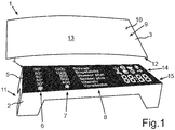
- Fig. 1 is a schematic representation of an operating and display device 1 of a household appliance not shown in the figures - namely in the embodiment a washing machine - shown.
- the operating and display device 1 is a touch-sensitive LED display which has a large number of function symbols that can be backlit.
- the operating and display device 1 contains the following components: a light guide part 2 with functional symbols attached to it, as well as a disk 3.
- the light guide part 2 represents a light shaft which is designed to guide light.
- a writing film 5, which is for example a light mask, is arranged on a front side 4 of the light guide part 2, which faces the pane 3.
- the writing film 5 has a large number of function characters, namely three columns of function characters in the exemplary embodiment, namely a first column of function characters 6, a second column of function characters 7 and a third column of function characters 8.
- the first column of function characters 6 symbolize each have a different value for an operating temperature of the washing machine.
- the function symbols 6 thus represent parameter values for the "operating temperature” parameter.
- the second column of function symbols 7 each symbolize a different value for a speed of the laundry drum for a spin mode of the washing machine.
- the function symbols 7 thus represent parameter values for the parameter “speed”.
- the third column of function symbols 8 contains a large number of different designations for additional functions of the washing machine. These are: “Quick”, “Easy Iron”, “Water plus”, “Rinse plus”, “Intensiv
- the disk 3 is a transparent or translucent disk, which can be made of transparent plastic, for example. It can be tinted in color.
- the disk 3 is a plate-like, flat and inherently rigid element.
- a front side 9 of the pane 3 simultaneously forms a touch-sensitive actuation surface 10 which can be touched by the user in order to select a parameter value. By touching the actuation surface 10, the user can do the above Set the parameters of the washing machine or select the specified parameter values. This is done by simply tapping the function symbols 6, 7, 8.
- the sensor electrode 13 is thus arranged in an overlap with the function symbols 6, 7, 8.
- the sensor electrode 13 lies over the function symbols 6, 7, 8, so that by touching the actuation surface 10 in an overlapping area with one of the function symbols 6, 7, 8, the parameter value assigned to this function symbol 6, 7, 8 can be selected, which for example is signaled by backlighting this selected function symbol 6, 7, 8.
- an in Fig. 1 evaluation device not shown provided to identify the point of contact at which the operator touches the actuation surface 10.
- a display area 15 with four seven-segment displays, which are used to display a period of time until the completion of a washing process serve. The remaining time of the washing process is thus displayed by means of the display area 15.
- the pane 3 made of transparent plastic is welded into a control panel of the washing machine.
- the application of the sensor electrode 13 to the pane 3 has its limits in the prior art if the pane 3 or its rear side 12 is designed three-dimensionally or if the pane 3 is concave or convex.
- a trade-off must be made here between the flexibility and configuration of the operating and display device 1 on the one hand and the technical possibility of applying the sensor electrode 13 on the other.
- so-called ITO layers indium tin oxide
- This material cannot be applied to any surface, so that a new solution had to be found in order to be able to apply the sensor electrode 13 to panes 3 of any design.
- the sensor electrode 13 is formed from a transparent and electrically conductive lacquer and / or a transparent and conductive adhesive. It has been found that such materials can be applied particularly easily to three-dimensional surfaces - for example to curved or arched panes 3 - without having to accept a restriction with regard to the shape of the operating and display device 1. On the one hand, the operating and display device 1 or the pane 3 can thus be shaped or configured as desired; on the other hand, an effective and reliable application of the sensor electrode 13 to the pane 3 is also made possible.
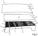
- FIG. 2 an operating and display device 1 'of a washing machine according to a second embodiment of the invention is shown.
- the operating and display device 1 ' corresponds essentially to the operating and display device 1 according to FIG Fig. 1 so that only the differences between them are explained in more detail below:
- the sensor electrode 13 ' is attached to a flexible film 16 made of plastic, which can be a single-layer or multi-layer film.
- the film 16 is - like the pane 3 '- made of a transparent material.
- the sensor electrode 13 ′ can extend over the entire surface of the film 16, for example.
- the sensor electrode 13 ' is preferably attached to a rear side of the film 16 which faces the light guide part 2'.
- the sensor electrode 13 ' can be electrically coupled to the evaluation device mentioned without much effort.
- the film 16 rests on the one hand on the rear side 12 'of the pane 3' and on the other hand on the front side 4 'of the light guide part 2'.
- the disk 3 ' is therefore free of electrically conductive elements.
- the sensor electrode 13 ′ is formed from an electrically conductive and transparent lacquer and / or adhesive, which preferably contain CNT.
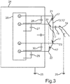
- the evaluation device also contains voltage generating means and tapping means 26 which are designed to apply an electrical voltage to the sensor electrode 13, 13 'and to tap electrical currents to the sensor electrode 13, 13'.
- an electrical voltage V with respect to ground 25 is applied to each corner 20 to 23.
- These electrical voltages can be the same voltages or else voltages each with a different amplitude.
- the voltages V can be direct voltages or alternating voltages.
- Each corner 20 to 23 is also connected to a capacitor 27, 28, 29, 30.
- the capacitors 27 to 30 can be connected to the ground 25.
- the evaluation device 24 thus detects the electrical currents at the corners 20 to 23 of the sensor electrode 13, 13 '. Depending on these currents - depending on, for example From a ratio of these currents - the evaluation device 24 can determine the point of contact. If the actuating surface 10, 10 'is not touched, no electrical current flows through the sensor electrode 13, 13', and the capacitors 27 to 30 are charged. If the actuating surface 10, 10 'is now touched, the contact capacitor 18 is formed. Currents flow from the capacitors 27 to 30 to the contact capacitor 18 and then on to the ground 25, namely via the finger 19. These currents or the charge shift in the capacitors 27 to 30 are now detected by the evaluation device 24, for example according to the above called charge transfer technology. When these currents are recorded, the evaluation device 24 can determine the point of contact, for example using a table or a formula. This can be defined, for example, by two coordinates, namely in the longitudinal direction and in the transverse direction of the sensor electrode 13, 13 '.
Landscapes
- Engineering & Computer Science (AREA)
- Textile Engineering (AREA)
- Chemical & Material Sciences (AREA)
- Combustion & Propulsion (AREA)
- Mechanical Engineering (AREA)
- General Engineering & Computer Science (AREA)
- Push-Button Switches (AREA)
- Switches That Are Operated By Magnetic Or Electric Fields (AREA)
- Cookers (AREA)
- Electronic Switches (AREA)
Claims (13)
- Appareil ménager avec un dispositif de commande et d'affichage tactile (1, 1'), lequel présente une unité d'affichage (11, 11') pour l'affichage d'informations de commande et une pièce de support transparente (3, 16) sur laquelle une électrode de détection capacitive (13, 13') est disposée sous la forme d'une pièce d'un condensateur à effleurement (18), disposé en chevauchement avec l'unité d'affichage (11, 11') et en chevauchement avec une surface d'actionnement tactile (10, 10') du dispositif de commande et d'affichage (1, 1'), caractérisé en ce que l'électrode de détection (13, 13') est formée par un vernis et/ou un adhésif transparent(s) et conducteur(s) d'électricité, dans lequel le vernis et/ou l'adhésif contient/contiennent des nanotubes en carbone.
- Appareil ménager selon la revendication 1, dans lequel l'électrode de détection (13, 13') s'étend sur une zone d'extension au moins prépondérante, en particulier totale, de l'unité d'affichage (11, 11') et le dispositif de commande et d'affichage (1, 1') comprend :- des moyens générateurs de tension pour l'application d'une tension électrique sur l'électrode de détection (13, 13'),- des moyens de prélèvement (26) pour le prélèvement respectivement d'un courant électrique en au moins deux endroits de prélèvement (20 - 23) de l'électrode de détection (13, 13') et- un dispositif d'évaluation (24) conçu afin de déterminer, en fonction des courants prélevés, un endroit d'effleurement auquel un utilisateur effleure la surface d'actionnement (10, 10') par-dessus l'électrode de détection (13, 13').
- Appareil ménager selon l'une des revendications précédentes, dans lequel le dispositif de commande et d'affichage (1, 1') comprend une vitre (3, 3') en forme de plaque, transparente et non conductrice d'électricité, dont le côté avant (9, 9') forme la surface d'actionnement tactile (10, 10').
- Appareil ménager selon la revendication 3, dans lequel la pièce de support (3, 16) est la vitre (3) et l'électrode de détection (13, 13') est disposée en un côté arrière (12, 12') de la vitre (3, 3'), dans lequel la vitre (3, 3') est disposée de telle façon par rapport à l'unité d'affichage (11, 11') que l'électrode de détection (13, 13') est, d'une part, contiguë au côté arrière (12, 12') de la vitre (3, 3') et, d'autre part, à un côté avant (4, 4') de l'unité d'affichage (11, 11').
- Appareil ménager selon la revendication 3, dans lequel la pièce de support (3, 16) est formée sous la forme d'un film transparent et flexible (16) et l'électrode de détection (13, 13') est apposée sur le film (16), dans lequel le film (16) est apposé de telle façon sur l'unité d'affichage (11, 11') que le film (16) est, d'une part, contigu à un côté arrière (12, 12') de la vitre (3, 3') et, d'autre part, à l'unité d'affichage (11, 11').
- Appareil ménager selon l'une des revendications 2 à 5, dans lequel les moyens de prélèvement (26) pour le prélèvement respectivement d'un courant électrique sont formés en quatre endroits de prélèvement différents (20 - 23) de l'électrode de détection (13, 13'), en particulier en chacun des coins (20 - 23) de l'électrode de détection rectangulaire (13, 13'), et le dispositif d'évaluation (24) est conçu afin de déterminer l'endroit d'affleurement en fonction des courants prélevés.
- Appareil ménager selon l'une des revendications 2 à 6, dans lequel les endroits de prélèvement (20 - 23) de l'électrode de détection (13, 13') sont respectivement électriquement couplés à un condensateur (27 - 30) et le courant électrique respectif est saisissable sous forme de déplacement de charge sur le condensateur (27 à 30) en raison de l'effleurement de la surface d'actionnement (10, 10').
- Appareil ménager selon l'une des revendications 2 à 7, dans lequel le dispositif d'évaluation (24) est conçu afin de déterminer l'endroit d'affleurement en fonction d'un rapport entre les courants prélevés.
- Appareil ménager selon l'une des revendications 2 à 8, dans lequel les moyens générateurs de tension pour l'application respectivement d'une tension électrique (V) sont formés en au moins deux, en particulier en quatre, endroits différents de l'électrode de détection (13, 13').
- Appareil ménager selon la revendication 9, dans lequel les tensions électriques (V) sont des tensions continues.
- Appareil ménager selon la revendication 9, dans lequel les tensions électriques sont des tensions alternatives (V), en particulier avec respectivement une fréquence différente.
- Appareil ménager selon l'une des revendications précédentes, dans lequel l'unité d'affichage (11, 11') comprend- une pièce de guidage de lumière (2, 2') pour le guidage de lumière, sur laquelle au moins un symbole de fonction (6, 7, 8, 6', 7', 8') est disposé sous forme d'information de commande en chevauchement avec l'électrode de détection (13, 13'), et- un dispositif lumineux pour le rétro-éclairage du symbole de fonction (6, 7, 8, 6', 7', 8'), lorsqu'un utilisateur effleure la surface d'actionnement tactile (10, 10') dans une zone de chevauchement avec le symbole de fonction (6, 7, 8, 6', 7', 8').
- Appareil ménager selon la revendication 12, dans lequel une pluralité de symboles de fonction (6, 7, 8, 6', 7', 8') sont disposés sur la pièce de guidage de lumière (2, 2') en chevauchement avec l'électrode de détection commune (13, 13') et l'effleurement de la surface d'actionnement (10, 10') dans une zone de chevauchement avec un des symboles de fonction (6, 7, 8, 6', 7', 8') permet de faire ressortir ce même symbole de fonction (6, 7, 8, 6', 7', 8') de façon visuelle au moyen du dispositif lumineux.
Applications Claiming Priority (2)
| Application Number | Priority Date | Filing Date | Title |
|---|---|---|---|
| DE102011081332A DE102011081332A1 (de) | 2011-08-22 | 2011-08-22 | Haushaltsgerät mit einer berührungssensitiven Bedien- und Anzeigeeinrichtung |
| PCT/EP2012/065817 WO2013026732A2 (fr) | 2011-08-22 | 2012-08-13 | Appareil électroménager équipé d'un dispositif de commande et d'affichage tactile |
Publications (2)
| Publication Number | Publication Date |
|---|---|
| EP2748368A2 EP2748368A2 (fr) | 2014-07-02 |
| EP2748368B1 true EP2748368B1 (fr) | 2021-03-31 |
Family
ID=46758727
Family Applications (1)
| Application Number | Title | Priority Date | Filing Date |
|---|---|---|---|
| EP12753091.3A Active EP2748368B1 (fr) | 2011-08-22 | 2012-08-13 | Appareil électroménager équipé d'un dispositif de commande et d'affichage tactile |
Country Status (5)
| Country | Link |
|---|---|
| EP (1) | EP2748368B1 (fr) |
| CN (1) | CN103764892A (fr) |
| DE (1) | DE102011081332A1 (fr) |
| RU (1) | RU2586829C2 (fr) |
| WO (1) | WO2013026732A2 (fr) |
Families Citing this family (5)
| Publication number | Priority date | Publication date | Assignee | Title |
|---|---|---|---|---|
| DE102013113772A1 (de) | 2013-12-10 | 2015-06-11 | Pas Deutschland Gmbh | Verfahren zur Bedienerführung, Blendenbauteil, Herstellung eines Blendenbauteils sowie Haushaltsgerät mit einem Blendenbauteil |
| IT201600107154A1 (it) * | 2016-10-25 | 2018-04-25 | Candy Spa | Cruscotto per elettrodomestici ed elettrodomestico dotato di tale cruscotto. |
| DE102018209950A1 (de) * | 2018-06-20 | 2019-12-24 | BSH Hausgeräte GmbH | Steuervorrichtung für ein Hausgerät |
| DE102019007379A1 (de) * | 2019-10-23 | 2021-04-29 | Emz-Hanauer Gmbh & Co. Kgaa | Sensor zum Einbau in ein elektrisches Haushaltsgerät |
| WO2023115730A1 (fr) * | 2021-12-24 | 2023-06-29 | 佛山市顺德区美的洗涤电器制造有限公司 | Appareil électroménager, et procédé de commande et appareil de commande associés, et support de stockage lisible |
Citations (1)
| Publication number | Priority date | Publication date | Assignee | Title |
|---|---|---|---|---|
| DE102007048222A1 (de) * | 2007-10-08 | 2009-04-09 | Gräf, Stefan | Berührungsempfindlicher Bildschirm in Drucktechnik |
Family Cites Families (13)
| Publication number | Priority date | Publication date | Assignee | Title |
|---|---|---|---|---|
| DE2824973A1 (de) | 1978-06-07 | 1979-12-20 | Euro Hausgeraete Gmbh | Verfahren und vorrichtung zur steuerung der programmwahl bei elektrischen haushaltgeraeten |
| US4293734A (en) * | 1979-02-23 | 1981-10-06 | Peptek, Incorporated | Touch panel system and method |
| DE20119700U1 (de) * | 2001-11-29 | 2002-02-14 | E.G.O. Control Systems GmbH & Co. KG, 72336 Balingen | Sensorvorrichtung |
| DE10236718A1 (de) | 2002-08-06 | 2004-02-12 | E.G.O. Control Systems Gmbh & Co. Kg | Elektrohaushaltsgerät mit Anzeigeeinrichtung |
| DE10326684A1 (de) * | 2003-06-03 | 2004-12-23 | Ego Control Systems Gmbh + Co. Kg | Sensorvorrichtung |
| DE102005032513B4 (de) * | 2005-07-12 | 2011-12-22 | Epcos Ag | Schichtelektrode für elektrochemische Doppelschichtkondensatoren, Herstellungsverfahren und elektrochemischer Doppelschichtkondensator |
| KR100790216B1 (ko) * | 2006-10-17 | 2008-01-02 | 삼성전자주식회사 | 전도성 분산제를 이용한 cnt 투명전극 및 그의 제조방법 |
| WO2008090887A1 (fr) * | 2007-01-22 | 2008-07-31 | Panasonic Corporation | Dispositif de cuisson |
| DE102007004889B4 (de) * | 2007-01-31 | 2009-04-16 | BSH Bosch und Siemens Hausgeräte GmbH | Kapazitiver Inkrementalgeber und Haushaltsgerät mit einem solchen |
| DE102008049176B4 (de) * | 2008-09-26 | 2011-01-27 | Diehl Ako Stiftung & Co. Kg | Bedienblende für ein Haushaltsgerät sowie Haushaltsgerät mit einer solchen Bedienblende |
| CN101751172A (zh) * | 2008-12-08 | 2010-06-23 | 上海天马微电子有限公司 | 触摸位置检测方法及触摸屏 |
| DE102009011678A1 (de) * | 2009-02-23 | 2010-08-26 | E.G.O. Elektro-Gerätebau GmbH | Bedieneinrichtung für ein Elektro-Hausgerät und Bedienverfahren |
| CN201867784U (zh) * | 2010-09-08 | 2011-06-15 | 汕头超声显示器有限公司 | 一种电容触摸感应装置 |
-
2011
- 2011-08-22 DE DE102011081332A patent/DE102011081332A1/de not_active Withdrawn
-
2012
- 2012-08-13 RU RU2014109034/12A patent/RU2586829C2/ru active
- 2012-08-13 EP EP12753091.3A patent/EP2748368B1/fr active Active
- 2012-08-13 CN CN201280040809.6A patent/CN103764892A/zh active Pending
- 2012-08-13 WO PCT/EP2012/065817 patent/WO2013026732A2/fr not_active Ceased
Patent Citations (1)
| Publication number | Priority date | Publication date | Assignee | Title |
|---|---|---|---|---|
| DE102007048222A1 (de) * | 2007-10-08 | 2009-04-09 | Gräf, Stefan | Berührungsempfindlicher Bildschirm in Drucktechnik |
Also Published As
| Publication number | Publication date |
|---|---|
| RU2586829C2 (ru) | 2016-06-10 |
| WO2013026732A3 (fr) | 2013-05-02 |
| DE102011081332A1 (de) | 2013-02-28 |
| WO2013026732A2 (fr) | 2013-02-28 |
| EP2748368A2 (fr) | 2014-07-02 |
| RU2014109034A (ru) | 2015-09-27 |
| CN103764892A (zh) | 2014-04-30 |
Similar Documents
| Publication | Publication Date | Title |
|---|---|---|
| EP2748369B1 (fr) | Appareil ménager à système de commande et d'affichage tactile | |
| EP2723930B2 (fr) | Dispositif de commande et d'affichage d'un appareil menager et appareil menager | |
| EP1994216B1 (fr) | Agencement de bandeau de commande pour des appareils ménagers et procédé de fabrication d'un agencement de bandeau de commande | |
| EP2884187B2 (fr) | Procédé d'aide à l'utilisateur, composant d'écran, fabrication d'un composant d'écran et appareil ménager doté d'un composant d'écran | |
| EP3344812B1 (fr) | Appareil ménager dont le dispositif de manipulation réalisé sous la forme d'un écran tactile présente une facilité d'utilisation améliorée | |
| EP2019983A2 (fr) | Dispositif de saisie | |
| DE102017218243B3 (de) | Verfahren zum Herstellen zumindest eines Teils einer berührungssensitiven Bedieneinrichtung, berührungssensitive Bedieneinrichtung und Kraftfahrzeug | |
| EP3251213B1 (fr) | Panneau de commande tactile éclairé, procédé permettant de faire fonctionner ledit panneau de commande, ainsi qu'appareil ménager muni dudit panneau de commande | |
| EP2759060B1 (fr) | Dispositif de commande, par exemple interface homme-machine, en particulier pour un composant de véhicule | |
| EP3084961A1 (fr) | Dispositif d'entrée sensible au contact et/ou au rapprochement | |
| DE102005041114A1 (de) | Kapazitiver Stellstreifen und Haushaltsgerät mit einem solchen | |
| WO2012175336A2 (fr) | Dispositif de commande et d'affichage capacitif pour appareil électroménager et appareil électroménager comprenant un tel dispositif de commande et d'affichage | |
| DE202024105266U1 (de) | Kapazitive Bedieneinheit | |
| WO2013026732A2 (fr) | Appareil électroménager équipé d'un dispositif de commande et d'affichage tactile | |
| EP2422450B1 (fr) | Selecteur de programme pour un appareil électroménager en particulier une machine à laver | |
| DE202012103075U1 (de) | Bedienflächenelement, Bedieneinheit und Gerät | |
| DE102013214162A1 (de) | Bedienteil für eine Bedieneinrichtung und Bedieneinrichtung | |
| DE102017204771A1 (de) | Haushaltsgerät mit gegen elektromagnetische Störungen abgeschirmtem kapazitivem Touchscreen und Verfahren zu seiner Herstellung | |
| WO2012175393A1 (fr) | Dispositif de commande capacitif pour un appareil électroménager, ainsi qu'appareil électroménager | |
| DE102009036520B4 (de) | Bedienelement und Verfahren zum Auslösen einer Funktion eines elektrischen Gerätes in einem Fahrzeug | |
| DE202013011515U1 (de) | Berührungs- und/oder annäherungsempfindliche Eingabevorrichtung | |
| DE102015216167A1 (de) | Haushaltsgerät mit Befestigungssystem, hierfür geeignetes Befestigungssystem sowie Verfahren zur Herstellung des Haushaltsgerätes | |
| DE102020201735A1 (de) | Vorrichtung und Verfahren zur Erkennung von Berührungsbefehlen | |
| DE102013015227A1 (de) | Bedieneinrichtung für einen Kraftwagen | |
| DE102024126410A1 (de) | Kapazitive Bedieneinheit |
Legal Events
| Date | Code | Title | Description |
|---|---|---|---|
| PUAI | Public reference made under article 153(3) epc to a published international application that has entered the european phase |
Free format text: ORIGINAL CODE: 0009012 |
|
| 17P | Request for examination filed |
Effective date: 20140324 |
|
| AK | Designated contracting states |
Kind code of ref document: A2 Designated state(s): AL AT BE BG CH CY CZ DE DK EE ES FI FR GB GR HR HU IE IS IT LI LT LU LV MC MK MT NL NO PL PT RO RS SE SI SK SM TR |
|
| DAX | Request for extension of the european patent (deleted) | ||
| RAP1 | Party data changed (applicant data changed or rights of an application transferred) |
Owner name: BSH HAUSGERAETE GMBH |
|
| STAA | Information on the status of an ep patent application or granted ep patent |
Free format text: STATUS: EXAMINATION IS IN PROGRESS |
|
| 17Q | First examination report despatched |
Effective date: 20200402 |
|
| REG | Reference to a national code |
Ref country code: DE Ref legal event code: R079 Ref document number: 502012016699 Country of ref document: DE Free format text: PREVIOUS MAIN CLASS: D06F0033020000 Ipc: D06F0033000000 |
|
| GRAP | Despatch of communication of intention to grant a patent |
Free format text: ORIGINAL CODE: EPIDOSNIGR1 |
|
| STAA | Information on the status of an ep patent application or granted ep patent |
Free format text: STATUS: GRANT OF PATENT IS INTENDED |
|
| RIC1 | Information provided on ipc code assigned before grant |
Ipc: F24C 7/08 20060101ALN20201015BHEP Ipc: D06F 34/28 20200101ALN20201015BHEP Ipc: D06F 33/00 20200101AFI20201015BHEP Ipc: A47L 15/42 20060101ALN20201015BHEP Ipc: D06F 58/30 20200101ALN20201015BHEP |
|
| RIC1 | Information provided on ipc code assigned before grant |
Ipc: D06F 33/00 20200101AFI20201102BHEP Ipc: F24C 7/08 20060101ALN20201102BHEP Ipc: D06F 34/28 20200101ALN20201102BHEP Ipc: D06F 58/30 20200101ALN20201102BHEP Ipc: A47L 15/42 20060101ALN20201102BHEP |
|
| INTG | Intention to grant announced |
Effective date: 20201117 |
|
| GRAS | Grant fee paid |
Free format text: ORIGINAL CODE: EPIDOSNIGR3 |
|
| GRAA | (expected) grant |
Free format text: ORIGINAL CODE: 0009210 |
|
| STAA | Information on the status of an ep patent application or granted ep patent |
Free format text: STATUS: THE PATENT HAS BEEN GRANTED |
|
| AK | Designated contracting states |
Kind code of ref document: B1 Designated state(s): AL AT BE BG CH CY CZ DE DK EE ES FI FR GB GR HR HU IE IS IT LI LT LU LV MC MK MT NL NO PL PT RO RS SE SI SK SM TR |
|
| REG | Reference to a national code |
Ref country code: GB Ref legal event code: FG4D Free format text: NOT ENGLISH Ref country code: CH Ref legal event code: EP |
|
| REG | Reference to a national code |
Ref country code: DE Ref legal event code: R096 Ref document number: 502012016699 Country of ref document: DE Ref country code: AT Ref legal event code: REF Ref document number: 1377029 Country of ref document: AT Kind code of ref document: T Effective date: 20210415 |
|
| REG | Reference to a national code |
Ref country code: IE Ref legal event code: FG4D Free format text: LANGUAGE OF EP DOCUMENT: GERMAN |
|
| REG | Reference to a national code |
Ref country code: LT Ref legal event code: MG9D |
|
| PG25 | Lapsed in a contracting state [announced via postgrant information from national office to epo] |
Ref country code: NO Free format text: LAPSE BECAUSE OF FAILURE TO SUBMIT A TRANSLATION OF THE DESCRIPTION OR TO PAY THE FEE WITHIN THE PRESCRIBED TIME-LIMIT Effective date: 20210630 Ref country code: BG Free format text: LAPSE BECAUSE OF FAILURE TO SUBMIT A TRANSLATION OF THE DESCRIPTION OR TO PAY THE FEE WITHIN THE PRESCRIBED TIME-LIMIT Effective date: 20210630 Ref country code: FI Free format text: LAPSE BECAUSE OF FAILURE TO SUBMIT A TRANSLATION OF THE DESCRIPTION OR TO PAY THE FEE WITHIN THE PRESCRIBED TIME-LIMIT Effective date: 20210331 Ref country code: HR Free format text: LAPSE BECAUSE OF FAILURE TO SUBMIT A TRANSLATION OF THE DESCRIPTION OR TO PAY THE FEE WITHIN THE PRESCRIBED TIME-LIMIT Effective date: 20210331 |
|
| PG25 | Lapsed in a contracting state [announced via postgrant information from national office to epo] |
Ref country code: RS Free format text: LAPSE BECAUSE OF FAILURE TO SUBMIT A TRANSLATION OF THE DESCRIPTION OR TO PAY THE FEE WITHIN THE PRESCRIBED TIME-LIMIT Effective date: 20210331 Ref country code: LV Free format text: LAPSE BECAUSE OF FAILURE TO SUBMIT A TRANSLATION OF THE DESCRIPTION OR TO PAY THE FEE WITHIN THE PRESCRIBED TIME-LIMIT Effective date: 20210331 Ref country code: SE Free format text: LAPSE BECAUSE OF FAILURE TO SUBMIT A TRANSLATION OF THE DESCRIPTION OR TO PAY THE FEE WITHIN THE PRESCRIBED TIME-LIMIT Effective date: 20210331 |
|
| REG | Reference to a national code |
Ref country code: NL Ref legal event code: MP Effective date: 20210331 |
|
| PG25 | Lapsed in a contracting state [announced via postgrant information from national office to epo] |
Ref country code: SM Free format text: LAPSE BECAUSE OF FAILURE TO SUBMIT A TRANSLATION OF THE DESCRIPTION OR TO PAY THE FEE WITHIN THE PRESCRIBED TIME-LIMIT Effective date: 20210331 Ref country code: NL Free format text: LAPSE BECAUSE OF FAILURE TO SUBMIT A TRANSLATION OF THE DESCRIPTION OR TO PAY THE FEE WITHIN THE PRESCRIBED TIME-LIMIT Effective date: 20210331 Ref country code: LT Free format text: LAPSE BECAUSE OF FAILURE TO SUBMIT A TRANSLATION OF THE DESCRIPTION OR TO PAY THE FEE WITHIN THE PRESCRIBED TIME-LIMIT Effective date: 20210331 Ref country code: EE Free format text: LAPSE BECAUSE OF FAILURE TO SUBMIT A TRANSLATION OF THE DESCRIPTION OR TO PAY THE FEE WITHIN THE PRESCRIBED TIME-LIMIT Effective date: 20210331 Ref country code: CZ Free format text: LAPSE BECAUSE OF FAILURE TO SUBMIT A TRANSLATION OF THE DESCRIPTION OR TO PAY THE FEE WITHIN THE PRESCRIBED TIME-LIMIT Effective date: 20210331 |
|
| PG25 | Lapsed in a contracting state [announced via postgrant information from national office to epo] |
Ref country code: PT Free format text: LAPSE BECAUSE OF FAILURE TO SUBMIT A TRANSLATION OF THE DESCRIPTION OR TO PAY THE FEE WITHIN THE PRESCRIBED TIME-LIMIT Effective date: 20210802 Ref country code: PL Free format text: LAPSE BECAUSE OF FAILURE TO SUBMIT A TRANSLATION OF THE DESCRIPTION OR TO PAY THE FEE WITHIN THE PRESCRIBED TIME-LIMIT Effective date: 20210331 Ref country code: ES Free format text: LAPSE BECAUSE OF FAILURE TO SUBMIT A TRANSLATION OF THE DESCRIPTION OR TO PAY THE FEE WITHIN THE PRESCRIBED TIME-LIMIT Effective date: 20210331 Ref country code: SK Free format text: LAPSE BECAUSE OF FAILURE TO SUBMIT A TRANSLATION OF THE DESCRIPTION OR TO PAY THE FEE WITHIN THE PRESCRIBED TIME-LIMIT Effective date: 20210331 Ref country code: RO Free format text: LAPSE BECAUSE OF FAILURE TO SUBMIT A TRANSLATION OF THE DESCRIPTION OR TO PAY THE FEE WITHIN THE PRESCRIBED TIME-LIMIT Effective date: 20210331 Ref country code: IS Free format text: LAPSE BECAUSE OF FAILURE TO SUBMIT A TRANSLATION OF THE DESCRIPTION OR TO PAY THE FEE WITHIN THE PRESCRIBED TIME-LIMIT Effective date: 20210731 |
|
| REG | Reference to a national code |
Ref country code: DE Ref legal event code: R097 Ref document number: 502012016699 Country of ref document: DE |
|
| PG25 | Lapsed in a contracting state [announced via postgrant information from national office to epo] |
Ref country code: DK Free format text: LAPSE BECAUSE OF FAILURE TO SUBMIT A TRANSLATION OF THE DESCRIPTION OR TO PAY THE FEE WITHIN THE PRESCRIBED TIME-LIMIT Effective date: 20210331 Ref country code: AL Free format text: LAPSE BECAUSE OF FAILURE TO SUBMIT A TRANSLATION OF THE DESCRIPTION OR TO PAY THE FEE WITHIN THE PRESCRIBED TIME-LIMIT Effective date: 20210331 |
|
| PLBE | No opposition filed within time limit |
Free format text: ORIGINAL CODE: 0009261 |
|
| STAA | Information on the status of an ep patent application or granted ep patent |
Free format text: STATUS: NO OPPOSITION FILED WITHIN TIME LIMIT |
|
| 26N | No opposition filed |
Effective date: 20220104 |
|
| REG | Reference to a national code |
Ref country code: CH Ref legal event code: PL |
|
| PG25 | Lapsed in a contracting state [announced via postgrant information from national office to epo] |
Ref country code: MC Free format text: LAPSE BECAUSE OF FAILURE TO SUBMIT A TRANSLATION OF THE DESCRIPTION OR TO PAY THE FEE WITHIN THE PRESCRIBED TIME-LIMIT Effective date: 20210331 |
|
| REG | Reference to a national code |
Ref country code: BE Ref legal event code: MM Effective date: 20210831 |
|
| PG25 | Lapsed in a contracting state [announced via postgrant information from national office to epo] |
Ref country code: LI Free format text: LAPSE BECAUSE OF NON-PAYMENT OF DUE FEES Effective date: 20210831 Ref country code: CH Free format text: LAPSE BECAUSE OF NON-PAYMENT OF DUE FEES Effective date: 20210831 |
|
| PG25 | Lapsed in a contracting state [announced via postgrant information from national office to epo] |
Ref country code: IS Free format text: LAPSE BECAUSE OF FAILURE TO SUBMIT A TRANSLATION OF THE DESCRIPTION OR TO PAY THE FEE WITHIN THE PRESCRIBED TIME-LIMIT Effective date: 20210731 Ref country code: LU Free format text: LAPSE BECAUSE OF NON-PAYMENT OF DUE FEES Effective date: 20210813 |
|
| PG25 | Lapsed in a contracting state [announced via postgrant information from national office to epo] |
Ref country code: IE Free format text: LAPSE BECAUSE OF NON-PAYMENT OF DUE FEES Effective date: 20210813 Ref country code: BE Free format text: LAPSE BECAUSE OF NON-PAYMENT OF DUE FEES Effective date: 20210831 |
|
| REG | Reference to a national code |
Ref country code: AT Ref legal event code: MM01 Ref document number: 1377029 Country of ref document: AT Kind code of ref document: T Effective date: 20210813 |
|
| PG25 | Lapsed in a contracting state [announced via postgrant information from national office to epo] |
Ref country code: AT Free format text: LAPSE BECAUSE OF NON-PAYMENT OF DUE FEES Effective date: 20210813 |
|
| PG25 | Lapsed in a contracting state [announced via postgrant information from national office to epo] |
Ref country code: HU Free format text: LAPSE BECAUSE OF FAILURE TO SUBMIT A TRANSLATION OF THE DESCRIPTION OR TO PAY THE FEE WITHIN THE PRESCRIBED TIME-LIMIT; INVALID AB INITIO Effective date: 20120813 Ref country code: CY Free format text: LAPSE BECAUSE OF FAILURE TO SUBMIT A TRANSLATION OF THE DESCRIPTION OR TO PAY THE FEE WITHIN THE PRESCRIBED TIME-LIMIT Effective date: 20210331 |
|
| PG25 | Lapsed in a contracting state [announced via postgrant information from national office to epo] |
Ref country code: GR Free format text: LAPSE BECAUSE OF FAILURE TO SUBMIT A TRANSLATION OF THE DESCRIPTION OR TO PAY THE FEE WITHIN THE PRESCRIBED TIME-LIMIT Effective date: 20210331 |
|
| PG25 | Lapsed in a contracting state [announced via postgrant information from national office to epo] |
Ref country code: MK Free format text: LAPSE BECAUSE OF FAILURE TO SUBMIT A TRANSLATION OF THE DESCRIPTION OR TO PAY THE FEE WITHIN THE PRESCRIBED TIME-LIMIT Effective date: 20210331 |
|
| PG25 | Lapsed in a contracting state [announced via postgrant information from national office to epo] |
Ref country code: MT Free format text: LAPSE BECAUSE OF FAILURE TO SUBMIT A TRANSLATION OF THE DESCRIPTION OR TO PAY THE FEE WITHIN THE PRESCRIBED TIME-LIMIT Effective date: 20210331 |
|
| PGFP | Annual fee paid to national office [announced via postgrant information from national office to epo] |
Ref country code: DE Payment date: 20250831 Year of fee payment: 14 |
|
| PGFP | Annual fee paid to national office [announced via postgrant information from national office to epo] |
Ref country code: IT Payment date: 20250829 Year of fee payment: 14 |
|
| PGFP | Annual fee paid to national office [announced via postgrant information from national office to epo] |
Ref country code: GB Payment date: 20250822 Year of fee payment: 14 |
|
| PGFP | Annual fee paid to national office [announced via postgrant information from national office to epo] |
Ref country code: FR Payment date: 20250821 Year of fee payment: 14 |
|
| PG25 | Lapsed in a contracting state [announced via postgrant information from national office to epo] |
Ref country code: TR Free format text: LAPSE BECAUSE OF FAILURE TO SUBMIT A TRANSLATION OF THE DESCRIPTION OR TO PAY THE FEE WITHIN THE PRESCRIBED TIME-LIMIT Effective date: 20210331 |