EP2749869B1 - System and method for inspecting structures formed of composite materials during the fabrication thereof - Google Patents
System and method for inspecting structures formed of composite materials during the fabrication thereof Download PDFInfo
- Publication number
- EP2749869B1 EP2749869B1 EP13196385.2A EP13196385A EP2749869B1 EP 2749869 B1 EP2749869 B1 EP 2749869B1 EP 13196385 A EP13196385 A EP 13196385A EP 2749869 B1 EP2749869 B1 EP 2749869B1
- Authority
- EP
- European Patent Office
- Prior art keywords
- individual plies
- plies
- fabrication
- mutually parallel
- composite materials
- Prior art date
- Legal status (The legal status is an assumption and is not a legal conclusion. Google has not performed a legal analysis and makes no representation as to the accuracy of the status listed.)
- Not-in-force
Links
Images


Classifications
-
- G—PHYSICS
- G06—COMPUTING OR CALCULATING; COUNTING
- G06T—IMAGE DATA PROCESSING OR GENERATION, IN GENERAL
- G06T7/00—Image analysis
- G06T7/0002—Inspection of images, e.g. flaw detection
- G06T7/0004—Industrial image inspection
-
- B—PERFORMING OPERATIONS; TRANSPORTING
- B29—WORKING OF PLASTICS; WORKING OF SUBSTANCES IN A PLASTIC STATE IN GENERAL
- B29C—SHAPING OR JOINING OF PLASTICS; SHAPING OF MATERIAL IN A PLASTIC STATE, NOT OTHERWISE PROVIDED FOR; AFTER-TREATMENT OF THE SHAPED PRODUCTS, e.g. REPAIRING
- B29C70/00—Shaping composites, i.e. plastics material comprising reinforcements, fillers or preformed parts, e.g. inserts
- B29C70/04—Shaping composites, i.e. plastics material comprising reinforcements, fillers or preformed parts, e.g. inserts comprising reinforcements only, e.g. self-reinforcing plastics
- B29C70/28—Shaping operations therefor
- B29C70/30—Shaping by lay-up, i.e. applying fibres, tape or broadsheet on a mould, former or core; Shaping by spray-up, i.e. spraying of fibres on a mould, former or core
- B29C70/38—Automated lay-up, e.g. using robots, laying filaments according to predetermined patterns
-
- B—PERFORMING OPERATIONS; TRANSPORTING
- B29—WORKING OF PLASTICS; WORKING OF SUBSTANCES IN A PLASTIC STATE IN GENERAL
- B29C—SHAPING OR JOINING OF PLASTICS; SHAPING OF MATERIAL IN A PLASTIC STATE, NOT OTHERWISE PROVIDED FOR; AFTER-TREATMENT OF THE SHAPED PRODUCTS, e.g. REPAIRING
- B29C70/00—Shaping composites, i.e. plastics material comprising reinforcements, fillers or preformed parts, e.g. inserts
- B29C70/04—Shaping composites, i.e. plastics material comprising reinforcements, fillers or preformed parts, e.g. inserts comprising reinforcements only, e.g. self-reinforcing plastics
- B29C70/28—Shaping operations therefor
- B29C70/30—Shaping by lay-up, i.e. applying fibres, tape or broadsheet on a mould, former or core; Shaping by spray-up, i.e. spraying of fibres on a mould, former or core
- B29C70/38—Automated lay-up, e.g. using robots, laying filaments according to predetermined patterns
- B29C70/386—Automated tape laying [ATL]
-
- B—PERFORMING OPERATIONS; TRANSPORTING
- B29—WORKING OF PLASTICS; WORKING OF SUBSTANCES IN A PLASTIC STATE IN GENERAL
- B29C—SHAPING OR JOINING OF PLASTICS; SHAPING OF MATERIAL IN A PLASTIC STATE, NOT OTHERWISE PROVIDED FOR; AFTER-TREATMENT OF THE SHAPED PRODUCTS, e.g. REPAIRING
- B29C70/00—Shaping composites, i.e. plastics material comprising reinforcements, fillers or preformed parts, e.g. inserts
- B29C70/04—Shaping composites, i.e. plastics material comprising reinforcements, fillers or preformed parts, e.g. inserts comprising reinforcements only, e.g. self-reinforcing plastics
- B29C70/28—Shaping operations therefor
- B29C70/54—Component parts, details or accessories; Auxiliary operations, e.g. feeding or storage of prepregs or SMC after impregnation or during ageing
- B29C70/541—Positioning reinforcements in a mould, e.g. using clamping means for the reinforcement
-
- G—PHYSICS
- G01—MEASURING; TESTING
- G01N—INVESTIGATING OR ANALYSING MATERIALS BY DETERMINING THEIR CHEMICAL OR PHYSICAL PROPERTIES
- G01N21/00—Investigating or analysing materials by the use of optical means, i.e. using sub-millimetre waves, infrared, visible or ultraviolet light
- G01N21/84—Systems specially adapted for particular applications
- G01N21/88—Investigating the presence of flaws or contamination
-
- G—PHYSICS
- G01—MEASURING; TESTING
- G01N—INVESTIGATING OR ANALYSING MATERIALS BY DETERMINING THEIR CHEMICAL OR PHYSICAL PROPERTIES
- G01N21/00—Investigating or analysing materials by the use of optical means, i.e. using sub-millimetre waves, infrared, visible or ultraviolet light
- G01N21/84—Systems specially adapted for particular applications
- G01N21/88—Investigating the presence of flaws or contamination
- G01N21/95—Investigating the presence of flaws or contamination characterised by the material or shape of the object to be examined
-
- G—PHYSICS
- G01—MEASURING; TESTING
- G01N—INVESTIGATING OR ANALYSING MATERIALS BY DETERMINING THEIR CHEMICAL OR PHYSICAL PROPERTIES
- G01N21/00—Investigating or analysing materials by the use of optical means, i.e. using sub-millimetre waves, infrared, visible or ultraviolet light
- G01N21/84—Systems specially adapted for particular applications
- G01N2021/8472—Investigation of composite materials
Definitions
- the present invention relates generally to the fabrication of structures from composite materials.
- US 2007/0173966 relates to visual fiber placement inspection, and discloses a method and system of inspecting structures formed of composite materials during the fabrication thereof as defined respectively in the pre-amble of appended independent claims 1 and 5.
- a method for inspecting structures formed of composite materials during the fabrication thereof including: imaging multiple individual plies of a structure, whereby the locations and orientations of edge joints between adjacent courses of each ply are recorded; characterized by: providing a three-dimensional image file of the structure; and ascertaining from the three-dimensional image file mutual offsets in the locations of mutually parallel ones of the edge joints of different plies in the multiple individual plies.
- the individual plies each extend in an X-Y plane and are stacked in a Z-direction, perpendicular to the X-Y plane of each of the individual plies and the mutual offsets may be ascertained by comparing the location of each of the mutually parallel edge joints in the X-Y plane of each of the individual plies with the corresponding location of an edge joint which is mutually parallel thereto in the X-Y plane of another one of the individual plies.
- the individual plies are non-planar and the mutual offsets may be ascertained by comparing the location of each of the mutually parallel edge joints in each of the individual plies with the corresponding location of an edge joint which most closely corresponds thereto in location and orientation in another one of the individual plies.
- the imaging multiple individual plies of a structure takes place during fabrication of the structure at least between laying down of each of the multiple individual plies.
- a system for inspecting structures formed of composite materials during the fabrication thereof including: an imager operative to image multiple individual plies of a structure, whereby the locations and orientations of edge joints between adjacent courses of each ply are recorded; characterized by: an offset analyzer operative to ascertain mutual offsets in the locations of mutually parallel ones of the edge joints of different plies in the multiple individual plies; and an image file generator operative to provide a three-dimensional image file of the structure to the offset analyzer.
- the individual plies each extend in an X-Y plane and are stacked in a Z-direction, perpendicular to the X-Y plane of each of the individual plies and the mutual offsets may be ascertained by comparing the location of each of the mutually parallel edge joints in the X-Y plane of each of the individual plies with the corresponding location of an edge joint which is mutually parallel thereto in the X-Y plane of another one of the individual plies.
- the individual plies are non-planar and the mutual offsets may be ascertained by comparing the location of each of the mutually parallel edge joints in each of the individual plies with the corresponding location of an edge joint which most closely corresponds thereto in location and orientation in another one of the individual plies.
- the imager is operative to image the multiple individual plies during fabrication of the structure at least between laying down of each of the multiple individual plies.
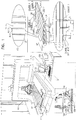
- FIG. 1 is a simplified illustration of a system for inspecting structures formed of composite materials during the fabrication thereof, constructed and operative in accordance with a preferred embodiment of the present invention.
- the system of the present invention is constructed and operative within the context of a Cincinnati Charger Tape Layer (CTL) machine 100, commercially available from Cincinnati Machine LLC of Hebron Kentucky, USA, preferably including a V5 head 102. It is appreciated that the system of the present invention is applicable to any suitable tape layup or fiber placement machine environment.
- CTL Cincinnati Charger Tape Layer
- multiple illuminators 104 preferably Nerlite® Machine Vision Lighting illuminators, such as dark field illuminators, DOAL® (Diffuse On-Axis Light) illuminators, or dome illuminators, commercially available from Microscan Systems, Inc., 700 SW 39 th St., Renton, WA 98057, are mounted on head 102.
- Nerlite® Machine Vision Lighting illuminators such as dark field illuminators, DOAL® (Diffuse On-Axis Light) illuminators, or dome illuminators, commercially available from Microscan Systems, Inc., 700 SW 39 th St., Renton, WA 98057
- multiple cameras 106 such as In-Sight Micro Series vision system cameras, commercially available from Cognex Corporation, One Vision Drive, Natick, MA 01760, are also mounted on head 102 to view multiple adjacent courses 108 of laid up tapes of a composite structure 110 in real time or near real time, thereby imaging multiple individual plies 112 of the composite structure, whereby the locations and orientations of edge joints 114 between adjacent courses 108 of each ply are preferably recorded.
- Edge joints 114 may be butt joints, at which edges of adjacent courses 108 touch each other, gap joints, at which edges of adjacent courses 108 are separated from each other by a separation S, or overlap joints at which edges of adjacent courses 108 overlap each other.
- Outputs of cameras 106 are supplied to one or more computers 120 which provide a three-dimensional image file of the composite structure.
- This three-dimensional image file enables ascertaining mutual offsets in the locations of mutually parallel ones of edge joints 114 in multiple individual plies 112.
- One or more display 122 shows a desired view of the composite structure, enabling an operator to view in real time or near real time the locations and orientations of edge joints 114 between adjacent courses 108 of each ply as the courses 108 are laid on the composite structure.
- all of the courses 108 in three illustrated plies 112 are mutually parallel and gap joints 130 are defined between adjacent parallel courses 108 in each ply 112.
- the requirements for gap joints 130 are that the adjacent parallel courses 108 be separated by a distance of between 0 and 2.54 mm. Overlaps of adjacent courses and separations between adjacent courses of more than 2.54 mm are considered to be defects and are detected by the system and methodology of the present invention.
- the offset between gap joints 130 of parallel plies 112 is another important characteristic in the construction of composite structures.
- the offset between gap joints 130 of parallel plies 112 must be at least 12.7 mm. Offsets between gap joints 130 of parallel plies 112 less than 12.7 mm are considered to be defects and are detected by the system and methodology of the present invention.
- the computer 120 automatically provides an output indication when at least one mutual offset of the edge joints is less than a predetermined minimum offset.
- FIG. 2 is a simplified illustration of a system for inspecting structures formed of composite materials during the fabrication thereof, constructed and operative in accordance with another preferred embodiment of the present invention.
- the system of the present invention is constructed and operative within the context of a Cincinnati Charger Tape Layer (CTL) machine 200, commercially available from Cincinnati Machine LLC of Hebron Kentucky, USA, preferably including a V5 head 202. It is appreciated that the system of the present invention is applicable to any suitable tape layup or fiber placement machine environment.
- CTL Cincinnati Charger Tape Layer
- multiple illuminators 204 preferably Nerlite® Machine Vision Lighting illuminators, such as dark field illuminators, DOAL® (Diffuse On-Axis Light) illuminators, or dome illuminators, commercially available from Microscan Systems, Inc., 700 SW 39 th St., Renton, WA 98057, are mounted on the CTL machine 200.
- Nerlite® Machine Vision Lighting illuminators such as dark field illuminators, DOAL® (Diffuse On-Axis Light) illuminators, or dome illuminators, commercially available from Microscan Systems, Inc., 700 SW 39 th St., Renton, WA 98057
- multiple cameras 206 such as In-Sight Micro Series vision system cameras, commercially available from Cognex Corporation, One Vision Drive, Natick, MA 01760, are mounted above the CTL machine 200, preferably on a ceiling, to view multiple adjacent courses 208 of laid up tapes of a composite structure 210 in real time or near real time, thereby imaging multiple individual plies 212 of the composite structure, whereby the locations and orientations of edge joints 214 between adjacent courses 208 of each ply are preferably recorded.
- In-Sight Micro Series vision system cameras commercially available from Cognex Corporation, One Vision Drive, Natick, MA 01760
- Outputs of cameras 206 are supplied to one or more computers 220 which provide a three-dimensional image file of the composite structure. It is appreciated that whereas in the embodiment of Fig. 1 , at any one time only a relatively small region of the composite structure 210 is viewed, in the embodiment of Fig. 2 , nearly the entire composite structure 210 is viewed.
- This three-dimensional image file enables ascertaining mutual offsets in the locations of mutually parallel ones of edge joints 214 in multiple individual plies 212.
- One or more display 222 shows a desired view of the composite structure, enabling an operator to view in real time or near real time the locations and orientations of edge joints 214 between adjacent courses 208 of each ply as the courses 208 are laid on the composite structure.
- all of the courses 208 in three illustrated plies 212 are mutually parallel and gap joints 230 are defined between adjacent parallel courses 208 in each ply 212.
- gap joints 230 are that the adjacent parallel courses 208 be separated by a distance of between 0 and 2.54 mm. Overlaps of adjacent courses and separations between adjacent courses of more than 2.54 mm are considered to be defects and are detected by the system and methodology of the present invention.
- the offset between gap joints 230 of parallel plies 212 is another important characteristic in the construction of composite structures, even when those plies are not adjacent each other in the composite structure.
- the offset between gap joints 230 of parallel plies 212 must be at least 12.7 mm. Offsets between gap joints 230 of parallel plies 212 less than 12.7 mm are considered to be defects and are detected by the system and methodology of the present invention.
- each plies 212 each including five adjacent courses 208, are shown.
- the separation between adjacent courses 208 at each gap joint 230 is designated as S and the offset between gap joints of parallel plies is designated as O. It is appreciated that the offset between gap joints is normally equivalent to the offset between edge joints between adjacent courses.
- the computer 220 automatically provides an output indication when at least one mutual offset of the edge joints is less than a predetermined minimum offset.
- FIG. 3 is a simplified illustration of a system for inspecting structures formed of composite materials during the fabrication thereof, constructed and operative in accordance with yet another preferred embodiment of the present invention.
- the system of the present invention is shown alongside a Cincinnati Charger Tape Layer (CTL) machine 300, commercially available from Cincinnati Machine LLC of Hebron Kentucky, USA, preferably including a V5 head 302.
- CTL Cincinnati Charger Tape Layer
- the operation of the system of the present invention is generally independent of the operation of the CTL machine 300 other than to the extent that the gantry 303 of the CTL machine must be out of the way and stationary during the imaging operation of the system of the present invention. It is appreciated that the system of the present invention is useful with any suitable tape layup or fiber placement machine environment.
- multiple illuminators 304 preferably Nerlite® Machine Vision Lighting illuminators, such as dark field illuminators, DOAL® (Diffuse On-Axis Light) illuminators, or dome illuminators, commercially available from Microscan Systems, Inc., 700 SW 39 th St., Renton, WA 98057, are mounted on a special purpose gantry 305.
- Nerlite® Machine Vision Lighting illuminators such as dark field illuminators, DOAL® (Diffuse On-Axis Light) illuminators, or dome illuminators, commercially available from Microscan Systems, Inc., 700 SW 39 th St., Renton, WA 98057
- multiple cameras 306 such as In-Sight Micro Series vision system cameras, commercially available from Cognex Corporation, One Vision Drive, Natick, MA 01760, are also mounted on gantry 305 to view multiple adjacent courses 308 of laid up tapes of a composite structure 310 in real time or near real time, preferably after each ply 312 is laid down, thereby imaging multiple individual plies 312 of the composite structure, whereby the locations and orientations of edge joints 314 between adjacent courses 308 of each ply are preferably recorded.
- cameras 306 such as In-Sight Micro Series vision system cameras, commercially available from Cognex Corporation, One Vision Drive, Natick, MA 01760
- Outputs of cameras 306 are supplied to one or more computers 320 which provide a three-dimensional image file of the composite structure.
- This three-dimensional image file enables ascertaining mutual offsets in the locations of mutually parallel ones of edge joints 314 in multiple individual plies 312.
- One or more display 322 shows a desired view of the composite structure, enabling an operator to view in real time or near real time the locations and orientations of edge joints 314 between adjacent courses 308 of each ply as the courses 308 are laid on the composite structure.
- all of the courses 308 in three illustrated plies 312 are mutually parallel and gap joints 330 are defined between adjacent parallel courses 308 in each ply 312.
- gap joints 330 are that the adjacent parallel courses 308 be separated by a distance of between 0 and 2.54 mm. Overlaps of adjacent courses and separations between adjacent courses of more than 2.54 mm are considered to be defects and are detected by the system and methodology of the present invention.
- the offset between gap joints 330 of parallel plies 312 is another important characteristic in the construction of composite structures.
- the offset between gap joints 330 of parallel plies 312 must be at least 12.7 mm. Offsets between gap joints 330 of parallel plies 312 less than 12.7 mm are considered to be defects and are detected by the system and methodology of the present invention.
- the computer 320 automatically provides an output indication when at least one mutual offset of the edge joints is less than a predetermined minimum offset.
- Fig. 4 is a simplified illustration of an output from the system of any of Figs. 1 - 3 showing plies in a generally planar orientation.
- the courses that make up plies 1, 3, 5 and 8 are mutually parallel; the courses that make up plies 2 and 7 are mutually parallel, but are angled relative to the courses that make up plies 1, 3, 5 and 8, and the courses that make up plies 4 and 6 are each not parallel to courses in any of the other plies in the illustrated composite article.
- Fig. 4 illustrates, at A, a cross-sectional cut taken from a three dimensional map automatically produced by the system of the present invention which clearly shows and emphasizes both the separation, designated S, between adjacent courses 408 at each gap joint 430 in mutually parallel plies 1, 3, 5 and 8, and the offset, designated O, between gap joints 430 of mutually parallel plies 1, 3, 5 and 8.
- Fig. 4 illustrates, at B, a cross-sectional cut taken from a three dimensional map automatically produced by the system of the present invention which clearly shows and emphasizes both the separation, designated S, between adjacent courses 408 at each gap joint 430 in mutually parallel plies 2 & 7, and the offset, designated O, between gap joints 430 of mutually parallel plies 2 & 7.
- Fig. 5 is a simplified illustration of an output from the system of any of Figs. 1 - 3 showing plies in a generally non-planar orientation.
- the courses 508 that make up plies 1, 3, 5 and 8 are mutually parallel; the courses that make up plies 2 and 7 are mutually parallel but are angled relative to the courses that make up plies 1, 3, 5 and 8 and the courses that make up plies 4 and 6 are each not parallel to courses in any of the other plies in the illustrated composite article.
- Fig. 5 illustrates, at A, a cross-sectional cut taken from a three dimensional map automatically produced by the system of the present invention which clearly shows and emphasizes both the separation, designated S, between adjacent courses 508 at each gap joint 530 in mutually parallel plies 1, 3, 5 and 8, and the offset, designated O, between gap joints 530 of mutually parallel plies 1, 3, 5 and 8.
- Fig. 5 illustrates, at B, a cross-sectional cut taken from a three dimensional map automatically produced by the system of the present invention which clearly shows and emphasizes both the separation, designated S, between adjacent courses 508 at each gap joint 530 in mutually parallel plies 2 & 7, and the offset, designated O, between gap joints 530 of mutually parallel plies 2 & 7.
Landscapes
- Engineering & Computer Science (AREA)
- Chemical & Material Sciences (AREA)
- Composite Materials (AREA)
- Mechanical Engineering (AREA)
- General Physics & Mathematics (AREA)
- Physics & Mathematics (AREA)
- General Health & Medical Sciences (AREA)
- Pathology (AREA)
- Analytical Chemistry (AREA)
- Biochemistry (AREA)
- Health & Medical Sciences (AREA)
- Robotics (AREA)
- Immunology (AREA)
- Life Sciences & Earth Sciences (AREA)
- Quality & Reliability (AREA)
- Computer Vision & Pattern Recognition (AREA)
- Theoretical Computer Science (AREA)
- Image Processing (AREA)
- Length Measuring Devices By Optical Means (AREA)
- Laminated Bodies (AREA)
- Investigating Materials By The Use Of Optical Means Adapted For Particular Applications (AREA)
Priority Applications (1)
| Application Number | Priority Date | Filing Date | Title |
|---|---|---|---|
| PL13196385T PL2749869T3 (pl) | 2012-12-26 | 2013-12-10 | Układ i sposób kontroli struktur utworzonych z materiałów kompozytowych podczas ich wytwarzania |
Applications Claiming Priority (1)
| Application Number | Priority Date | Filing Date | Title |
|---|---|---|---|
| US13/727,196 US8983171B2 (en) | 2012-12-26 | 2012-12-26 | System and method for inspecting structures formed of composite materials during the fabrication thereof |
Publications (2)
| Publication Number | Publication Date |
|---|---|
| EP2749869A1 EP2749869A1 (en) | 2014-07-02 |
| EP2749869B1 true EP2749869B1 (en) | 2019-04-03 |
Family
ID=50023372
Family Applications (1)
| Application Number | Title | Priority Date | Filing Date |
|---|---|---|---|
| EP13196385.2A Not-in-force EP2749869B1 (en) | 2012-12-26 | 2013-12-10 | System and method for inspecting structures formed of composite materials during the fabrication thereof |
Country Status (9)
| Country | Link |
|---|---|
| US (1) | US8983171B2 (es) |
| EP (1) | EP2749869B1 (es) |
| CA (1) | CA2835643C (es) |
| DK (1) | DK2749869T3 (es) |
| ES (1) | ES2732737T3 (es) |
| PL (1) | PL2749869T3 (es) |
| PT (1) | PT2749869T (es) |
| SG (1) | SG2013089396A (es) |
| TR (1) | TR201909169T4 (es) |
Cited By (2)
| Publication number | Priority date | Publication date | Assignee | Title |
|---|---|---|---|---|
| US11436390B2 (en) | 2020-06-18 | 2022-09-06 | The Boeing Company | Fiber path planning to reduce in-plane curvature |
| US12240178B1 (en) | 2020-06-18 | 2025-03-04 | The Boeing Company | Layup strategy analysis |
Families Citing this family (10)
| Publication number | Priority date | Publication date | Assignee | Title |
|---|---|---|---|---|
| US9759547B2 (en) * | 2014-08-19 | 2017-09-12 | The Boeing Company | Systems and methods for fiber placement inspection during fabrication of fiber-reinforced composite components |
| FR3027296B1 (fr) * | 2014-10-16 | 2016-11-04 | Aerolia | Procede et dispositif d'application d'un ruban adhesif sur un raidisseur |
| US10668673B2 (en) * | 2015-05-18 | 2020-06-02 | Flightware, Inc. | Systems and methods for automated composite layup quality assurance |
| AT518548B1 (de) * | 2016-09-28 | 2017-11-15 | Engel Austria Gmbh | Handhabungsgerät |
| US10661512B2 (en) | 2017-04-25 | 2020-05-26 | The Boeing Company | Measurement of ply boundaries |
| US10654228B2 (en) * | 2017-07-28 | 2020-05-19 | The Boeing Company | System and method for forming a part by automated fiber placement |
| GB2573764A (en) * | 2018-05-15 | 2019-11-20 | Rolls Royce Plc | Method of evaluating a composite sample |
| US10572989B2 (en) * | 2018-06-06 | 2020-02-25 | The Boeing Company | Chopped fiber additive manufacturing void detection |
| US10974465B2 (en) * | 2018-06-20 | 2021-04-13 | The Boeing Company | Method and system for generating a layup plan for forming a composite laminate |
| WO2023193217A1 (zh) * | 2022-04-08 | 2023-10-12 | 宁德时代新能源科技股份有限公司 | 连续复合料带的标记处理方法、装置和计算机设备 |
Citations (1)
| Publication number | Priority date | Publication date | Assignee | Title |
|---|---|---|---|---|
| US5562788A (en) * | 1994-09-20 | 1996-10-08 | The Boeing Company | Composite material laser flaw detection |
Family Cites Families (44)
| Publication number | Priority date | Publication date | Assignee | Title |
|---|---|---|---|---|
| US3853756A (en) | 1973-02-12 | 1974-12-10 | Westinghouse Electric Corp | Reverse pressure cleaning of supported semipermeable membranes |
| US4591400A (en) | 1984-05-15 | 1986-05-27 | United Technologies Corporation | Method of forming a fiber reinforced composite article of a complex configuration |
| US4780262A (en) | 1986-01-15 | 1988-10-25 | The Boeing Company | Method for making composite structures |
| US4693678A (en) | 1986-01-15 | 1987-09-15 | The Boeing Company | Male layup-female molding system for fabricating reinforced composite structures |
| US5016895A (en) | 1989-07-19 | 1991-05-21 | Cycle Composites, Inc. | Cycle fork with fiber reinforced resin blades and crown and method of making same |
| US5137071A (en) | 1989-07-21 | 1992-08-11 | Chemicals & Materials Enterprise Assoc. | Apparatus for forming a composite structure |
| US5087187A (en) | 1990-03-09 | 1992-02-11 | United Technologies Corporation | Apparatus for molding hollow composite articles having internal reinforcement structures |
| US5332178A (en) | 1992-06-05 | 1994-07-26 | Williams International Corporation | Composite wing and manufacturing process thereof |
| IT1262970B (it) | 1992-08-03 | 1996-07-23 | Alenia Aeritalia & Selenia | Sistema per la realizzazione distrutture in fibra di carbonio, e procedimento per detto, particolarmente idoneo per applicazioni aeronautiche. |
| US5419554A (en) | 1993-08-30 | 1995-05-30 | Quadrax Corporation | Sports racket frame |
| US5772950A (en) | 1994-08-31 | 1998-06-30 | The Boeing Company | Method of vacuum forming a composite |
| US5963660A (en) | 1996-09-26 | 1999-10-05 | The Boeing Company | Method and apparatus for detecting and measuring laps and gaps in composite materials |
| US6319346B1 (en) | 1997-04-23 | 2001-11-20 | Radius Engineering, Inc. | Method for manufacture of composite aircraft control surfaces |
| US6112617A (en) | 1997-06-26 | 2000-09-05 | Abrams; David Bartlett | Composite winch handles |
| US6041132A (en) * | 1997-07-29 | 2000-03-21 | General Electric Company | Computed tomography inspection of composite ply structure |
| US6513757B1 (en) | 1999-07-19 | 2003-02-04 | Fuji Jukogyo Kabushiki Kaisha | Wing of composite material and method of fabricating the same |
| US7681835B2 (en) | 1999-11-18 | 2010-03-23 | Rocky Mountain Composites, Inc. | Single piece co-cure composite wing |
| US6630221B1 (en) | 2000-07-21 | 2003-10-07 | Dexter Corporation | Monolithic expandable structures, methods of manufacture and composite structures |
| US6743504B1 (en) | 2001-03-01 | 2004-06-01 | Rohr, Inc. | Co-cured composite structures and method of making them |
| US6871684B2 (en) | 2002-08-13 | 2005-03-29 | The Boeing Company | System for identifying defects in a composite structure |
| IL157581A (en) | 2003-01-09 | 2004-08-31 | Ide Technologies Ltd | Direct osmosis membrane cleaning |
| US20050151007A1 (en) | 2003-02-04 | 2005-07-14 | Cadogan David P. | Deployable, rigidizable wing |
| US6896841B2 (en) | 2003-03-20 | 2005-05-24 | The Boeing Company | Molding process and apparatus for producing unified composite structures |
| US7197177B2 (en) * | 2003-08-29 | 2007-03-27 | Lowe Elvin P | Automated laminate inspection method |
| US8068659B2 (en) | 2003-12-02 | 2011-11-29 | The Boeing Company | Method and system for determining cumulative foreign object characteristics during fabrication of a composite structure |
| US8934702B2 (en) * | 2003-12-02 | 2015-01-13 | The Boeing Company | System and method for determining cumulative tow gap width |
| US7508971B2 (en) * | 2004-05-28 | 2009-03-24 | The Boeing Company | Inspection system using coordinate measurement machine and associated method |
| FI118122B (fi) | 2004-10-08 | 2007-07-13 | Patria Aerostructures Oy | Ilma-aluksen kääntyvä paneeli ja komposiittirakenteinen tukikappale |
| FR2879496B1 (fr) | 2004-12-16 | 2008-12-12 | Eurocopter France | Procede et dispositif de fabrication d'une carene de rotor d'helicoptere, et carene obtenue |
| US7889907B2 (en) | 2005-01-12 | 2011-02-15 | The Boeing Company | Apparatus and methods for inspecting tape lamination |
| US8668793B2 (en) | 2005-08-11 | 2014-03-11 | The Boeing Company | Systems and methods for in-process vision inspection for automated machines |
| US7835567B2 (en) | 2006-01-24 | 2010-11-16 | Ingersoll Machine Tools, Inc. | Visual fiber placement inspection |
| US7362437B2 (en) | 2006-03-28 | 2008-04-22 | The Boeing Company | Vision inspection system device and method |
| FR2903626B1 (fr) | 2006-07-12 | 2008-10-10 | Eads Space Transp Sas Soc Par | Assemblage de preimpregnes pour la realisation de structures par exemple a deploiement par gonflage |
| US8218852B2 (en) * | 2007-05-08 | 2012-07-10 | Spirit Aerosystems, Inc. | System and method for repairing composite parts |
| US20090039566A1 (en) | 2007-08-07 | 2009-02-12 | Rodman William L | Composite structures and methods of making same |
| US7555404B2 (en) | 2007-08-09 | 2009-06-30 | The Boeing Company | Methods and systems for automated ply boundary and orientation inspection |
| GB0803823D0 (en) | 2008-02-29 | 2008-04-09 | Victrex Mfg Ltd | Composite materials |
| DE102008013759B4 (de) | 2008-03-12 | 2012-12-13 | Airbus Operations Gmbh | Verfahren zur Herstellung eines integralen Faserverbundbauteils sowie Kernform zur Durchführung des Verfahrens |
| GB0818088D0 (en) * | 2008-10-03 | 2008-11-05 | Qinetiq Ltd | Composite evaluation |
| US8108058B2 (en) | 2009-02-09 | 2012-01-31 | The Boeing Company | Method of analyzing composite structures |
| US8303882B2 (en) | 2009-02-23 | 2012-11-06 | General Electric Company | Apparatus and method of making composite material articles |
| JP2011104905A (ja) * | 2009-11-18 | 2011-06-02 | Mitsubishi Heavy Ind Ltd | 複合材部品製造方法、複合材部品製造装置及び検査装置 |
| US20130011605A1 (en) | 2011-07-05 | 2013-01-10 | Israel Aerospace Industries Ltd. | Manufacture of articles formed of composite materials |
-
2012
- 2012-12-26 US US13/727,196 patent/US8983171B2/en not_active Expired - Fee Related
-
2013
- 2013-12-03 SG SG2013089396A patent/SG2013089396A/en unknown
- 2013-12-05 CA CA2835643A patent/CA2835643C/en not_active Expired - Fee Related
- 2013-12-10 EP EP13196385.2A patent/EP2749869B1/en not_active Not-in-force
- 2013-12-10 PT PT13196385T patent/PT2749869T/pt unknown
- 2013-12-10 ES ES13196385T patent/ES2732737T3/es active Active
- 2013-12-10 TR TR2019/09169T patent/TR201909169T4/tr unknown
- 2013-12-10 DK DK13196385.2T patent/DK2749869T3/da active
- 2013-12-10 PL PL13196385T patent/PL2749869T3/pl unknown
Patent Citations (1)
| Publication number | Priority date | Publication date | Assignee | Title |
|---|---|---|---|---|
| US5562788A (en) * | 1994-09-20 | 1996-10-08 | The Boeing Company | Composite material laser flaw detection |
Cited By (2)
| Publication number | Priority date | Publication date | Assignee | Title |
|---|---|---|---|---|
| US11436390B2 (en) | 2020-06-18 | 2022-09-06 | The Boeing Company | Fiber path planning to reduce in-plane curvature |
| US12240178B1 (en) | 2020-06-18 | 2025-03-04 | The Boeing Company | Layup strategy analysis |
Also Published As
| Publication number | Publication date |
|---|---|
| CA2835643A1 (en) | 2014-06-26 |
| PT2749869T (pt) | 2019-07-12 |
| CA2835643C (en) | 2018-05-01 |
| DK2749869T3 (da) | 2019-07-01 |
| ES2732737T3 (es) | 2019-11-25 |
| US8983171B2 (en) | 2015-03-17 |
| EP2749869A1 (en) | 2014-07-02 |
| TR201909169T4 (tr) | 2019-07-22 |
| US20140177936A1 (en) | 2014-06-26 |
| SG2013089396A (en) | 2014-07-30 |
| PL2749869T3 (pl) | 2019-10-31 |
Similar Documents
| Publication | Publication Date | Title |
|---|---|---|
| EP2749869B1 (en) | System and method for inspecting structures formed of composite materials during the fabrication thereof | |
| US9052294B2 (en) | Method and system for two-dimensional and three-dimensional inspection of a workpiece | |
| US20170248406A1 (en) | Laser vision inspection system and method | |
| US8533927B2 (en) | Full-scale architectural template and method for installing construction elements for exhibitions, trade shows, conventions and events without damaging carpet or floor | |
| EP2385340A1 (en) | Automatic system for quality control and position correction of taped parts | |
| CN109073498A (zh) | 用于扫描对象的移动飞行器和用于对象的损坏分析的系统 | |
| CN101499166A (zh) | 一种图像拼接方法及装置 | |
| JP2010249744A (ja) | ワイヤーハーネス外観検査用画像生成装置およびワイヤーハーネス外観検査用画像生成方法 | |
| JP2017116453A (ja) | 無人機を用いた構造物等の検査方法 | |
| JP2011079648A (ja) | 固定映像表示システム | |
| JP2012098170A (ja) | 画像データ処理システム | |
| JP7587948B2 (ja) | 検査システム | |
| CN104917947A (zh) | 一种火灾探测器摄像头的激光安装定位方法 | |
| EP3833601A1 (en) | Method for detecting a door status of an aircraft door | |
| US20130255056A1 (en) | Full-scale architectural template and method for installing construction elements for exhibitions, trade shows, conventions and events | |
| EP2502732A1 (en) | Method for producing composite material components, device for producing composite material components, and inspection device | |
| JP6514891B2 (ja) | 生産エリア撮影システム | |
| KR20150053582A (ko) | 적층 필름의 계면간 접합력을 측정하는 방법 및 장치 | |
| US11618591B2 (en) | Composite laminate damage detection method using an in-situ thermal gradient and expansion differences across the damage | |
| JP6833460B2 (ja) | 作業支援システム、作業方法、および処理装置 | |
| WO2025223627A1 (en) | Wind turbine component repair automation | |
| Cemenska et al. | Automated in-process inspection system for AFP machines | |
| KR20170025448A (ko) | 부재 위치 안내 장치 | |
| CN121564683A (zh) | 基于机器人影像的电缆沟施工审计方法及设备 | |
| WO2023067717A1 (ja) | 施設点検表示装置、情報処理装置、施設点検表示方法及び非一時的なコンピュータ可読媒体 |
Legal Events
| Date | Code | Title | Description |
|---|---|---|---|
| 17P | Request for examination filed |
Effective date: 20140103 |
|
| AK | Designated contracting states |
Kind code of ref document: A1 Designated state(s): AL AT BE BG CH CY CZ DE DK EE ES FI FR GB GR HR HU IE IS IT LI LT LU LV MC MK MT NL NO PL PT RO RS SE SI SK SM TR |
|
| AX | Request for extension of the european patent |
Extension state: BA ME |
|
| PUAI | Public reference made under article 153(3) epc to a published international application that has entered the european phase |
Free format text: ORIGINAL CODE: 0009012 |
|
| STAA | Information on the status of an ep patent application or granted ep patent |
Free format text: STATUS: EXAMINATION IS IN PROGRESS |
|
| 17Q | First examination report despatched |
Effective date: 20180604 |
|
| GRAP | Despatch of communication of intention to grant a patent |
Free format text: ORIGINAL CODE: EPIDOSNIGR1 |
|
| STAA | Information on the status of an ep patent application or granted ep patent |
Free format text: STATUS: GRANT OF PATENT IS INTENDED |
|
| INTG | Intention to grant announced |
Effective date: 20181221 |
|
| RAP1 | Party data changed (applicant data changed or rights of an application transferred) |
Owner name: ISRAEL AEROSPACE INDUSTRIES LTD. |
|
| GRAS | Grant fee paid |
Free format text: ORIGINAL CODE: EPIDOSNIGR3 |
|
| GRAA | (expected) grant |
Free format text: ORIGINAL CODE: 0009210 |
|
| STAA | Information on the status of an ep patent application or granted ep patent |
Free format text: STATUS: THE PATENT HAS BEEN GRANTED |
|
| AK | Designated contracting states |
Kind code of ref document: B1 Designated state(s): AL AT BE BG CH CY CZ DE DK EE ES FI FR GB GR HR HU IE IS IT LI LT LU LV MC MK MT NL NO PL PT RO RS SE SI SK SM TR |
|
| REG | Reference to a national code |
Ref country code: GB Ref legal event code: FG4D |
|
| REG | Reference to a national code |
Ref country code: CH Ref legal event code: EP Ref country code: AT Ref legal event code: REF Ref document number: 1116352 Country of ref document: AT Kind code of ref document: T Effective date: 20190415 |
|
| REG | Reference to a national code |
Ref country code: DE Ref legal event code: R096 Ref document number: 602013053223 Country of ref document: DE |
|
| REG | Reference to a national code |
Ref country code: IE Ref legal event code: FG4D |
|
| REG | Reference to a national code |
Ref country code: CH Ref legal event code: NV Representative=s name: DENNEMEYER AG, CH |
|
| REG | Reference to a national code |
Ref country code: DK Ref legal event code: T3 Effective date: 20190628 |
|
| REG | Reference to a national code |
Ref country code: NL Ref legal event code: FP |
|
| REG | Reference to a national code |
Ref country code: PT Ref legal event code: SC4A Ref document number: 2749869 Country of ref document: PT Date of ref document: 20190712 Kind code of ref document: T Free format text: AVAILABILITY OF NATIONAL TRANSLATION Effective date: 20190703 |
|
| REG | Reference to a national code |
Ref country code: NO Ref legal event code: T2 Effective date: 20190403 |
|
| REG | Reference to a national code |
Ref country code: SE Ref legal event code: TRGR |
|
| REG | Reference to a national code |
Ref country code: LT Ref legal event code: MG4D |
|
| PG25 | Lapsed in a contracting state [announced via postgrant information from national office to epo] |
Ref country code: HR Free format text: LAPSE BECAUSE OF FAILURE TO SUBMIT A TRANSLATION OF THE DESCRIPTION OR TO PAY THE FEE WITHIN THE PRESCRIBED TIME-LIMIT Effective date: 20190403 Ref country code: LT Free format text: LAPSE BECAUSE OF FAILURE TO SUBMIT A TRANSLATION OF THE DESCRIPTION OR TO PAY THE FEE WITHIN THE PRESCRIBED TIME-LIMIT Effective date: 20190403 Ref country code: AL Free format text: LAPSE BECAUSE OF FAILURE TO SUBMIT A TRANSLATION OF THE DESCRIPTION OR TO PAY THE FEE WITHIN THE PRESCRIBED TIME-LIMIT Effective date: 20190403 |
|
| REG | Reference to a national code |
Ref country code: ES Ref legal event code: FG2A Ref document number: 2732737 Country of ref document: ES Kind code of ref document: T3 Effective date: 20191125 |
|
| PG25 | Lapsed in a contracting state [announced via postgrant information from national office to epo] |
Ref country code: BG Free format text: LAPSE BECAUSE OF FAILURE TO SUBMIT A TRANSLATION OF THE DESCRIPTION OR TO PAY THE FEE WITHIN THE PRESCRIBED TIME-LIMIT Effective date: 20190703 Ref country code: GR Free format text: LAPSE BECAUSE OF FAILURE TO SUBMIT A TRANSLATION OF THE DESCRIPTION OR TO PAY THE FEE WITHIN THE PRESCRIBED TIME-LIMIT Effective date: 20190704 Ref country code: LV Free format text: LAPSE BECAUSE OF FAILURE TO SUBMIT A TRANSLATION OF THE DESCRIPTION OR TO PAY THE FEE WITHIN THE PRESCRIBED TIME-LIMIT Effective date: 20190403 Ref country code: RS Free format text: LAPSE BECAUSE OF FAILURE TO SUBMIT A TRANSLATION OF THE DESCRIPTION OR TO PAY THE FEE WITHIN THE PRESCRIBED TIME-LIMIT Effective date: 20190403 |
|
| PG25 | Lapsed in a contracting state [announced via postgrant information from national office to epo] |
Ref country code: IS Free format text: LAPSE BECAUSE OF FAILURE TO SUBMIT A TRANSLATION OF THE DESCRIPTION OR TO PAY THE FEE WITHIN THE PRESCRIBED TIME-LIMIT Effective date: 20190803 |
|
| REG | Reference to a national code |
Ref country code: DE Ref legal event code: R097 Ref document number: 602013053223 Country of ref document: DE |
|
| PG25 | Lapsed in a contracting state [announced via postgrant information from national office to epo] |
Ref country code: EE Free format text: LAPSE BECAUSE OF FAILURE TO SUBMIT A TRANSLATION OF THE DESCRIPTION OR TO PAY THE FEE WITHIN THE PRESCRIBED TIME-LIMIT Effective date: 20190403 Ref country code: RO Free format text: LAPSE BECAUSE OF FAILURE TO SUBMIT A TRANSLATION OF THE DESCRIPTION OR TO PAY THE FEE WITHIN THE PRESCRIBED TIME-LIMIT Effective date: 20190403 Ref country code: SK Free format text: LAPSE BECAUSE OF FAILURE TO SUBMIT A TRANSLATION OF THE DESCRIPTION OR TO PAY THE FEE WITHIN THE PRESCRIBED TIME-LIMIT Effective date: 20190403 |
|
| PLBE | No opposition filed within time limit |
Free format text: ORIGINAL CODE: 0009261 |
|
| STAA | Information on the status of an ep patent application or granted ep patent |
Free format text: STATUS: NO OPPOSITION FILED WITHIN TIME LIMIT |
|
| PG25 | Lapsed in a contracting state [announced via postgrant information from national office to epo] |
Ref country code: SM Free format text: LAPSE BECAUSE OF FAILURE TO SUBMIT A TRANSLATION OF THE DESCRIPTION OR TO PAY THE FEE WITHIN THE PRESCRIBED TIME-LIMIT Effective date: 20190403 |
|
| 26N | No opposition filed |
Effective date: 20200106 |
|
| PG25 | Lapsed in a contracting state [announced via postgrant information from national office to epo] |
Ref country code: SI Free format text: LAPSE BECAUSE OF FAILURE TO SUBMIT A TRANSLATION OF THE DESCRIPTION OR TO PAY THE FEE WITHIN THE PRESCRIBED TIME-LIMIT Effective date: 20190403 |
|
| REG | Reference to a national code |
Ref country code: DE Ref legal event code: R119 Ref document number: 602013053223 Country of ref document: DE |
|
| REG | Reference to a national code |
Ref country code: FI Ref legal event code: MAE |
|
| REG | Reference to a national code |
Ref country code: DK Ref legal event code: EBP Effective date: 20191231 Ref country code: NO Ref legal event code: MMEP |
|
| REG | Reference to a national code |
Ref country code: SE Ref legal event code: EUG |
|
| PG25 | Lapsed in a contracting state [announced via postgrant information from national office to epo] |
Ref country code: CZ Free format text: LAPSE BECAUSE OF NON-PAYMENT OF DUE FEES Effective date: 20191210 Ref country code: FI Free format text: LAPSE BECAUSE OF NON-PAYMENT OF DUE FEES Effective date: 20191210 |
|
| REG | Reference to a national code |
Ref country code: CH Ref legal event code: PL |
|
| REG | Reference to a national code |
Ref country code: NL Ref legal event code: MM Effective date: 20200101 |
|
| REG | Reference to a national code |
Ref country code: BE Ref legal event code: MM Effective date: 20191231 |
|
| PG25 | Lapsed in a contracting state [announced via postgrant information from national office to epo] |
Ref country code: MC Free format text: LAPSE BECAUSE OF FAILURE TO SUBMIT A TRANSLATION OF THE DESCRIPTION OR TO PAY THE FEE WITHIN THE PRESCRIBED TIME-LIMIT Effective date: 20190403 |
|
| GBPC | Gb: european patent ceased through non-payment of renewal fee |
Effective date: 20191210 |
|
| PG25 | Lapsed in a contracting state [announced via postgrant information from national office to epo] |
Ref country code: NL Free format text: LAPSE BECAUSE OF NON-PAYMENT OF DUE FEES Effective date: 20200101 |
|
| PG25 | Lapsed in a contracting state [announced via postgrant information from national office to epo] |
Ref country code: SE Free format text: LAPSE BECAUSE OF NON-PAYMENT OF DUE FEES Effective date: 20191211 Ref country code: GB Free format text: LAPSE BECAUSE OF NON-PAYMENT OF DUE FEES Effective date: 20191210 Ref country code: NO Free format text: LAPSE BECAUSE OF NON-PAYMENT OF DUE FEES Effective date: 20191231 Ref country code: IT Free format text: LAPSE BECAUSE OF NON-PAYMENT OF DUE FEES Effective date: 20191210 Ref country code: FR Free format text: LAPSE BECAUSE OF NON-PAYMENT OF DUE FEES Effective date: 20191231 Ref country code: DE Free format text: LAPSE BECAUSE OF NON-PAYMENT OF DUE FEES Effective date: 20200701 Ref country code: IE Free format text: LAPSE BECAUSE OF NON-PAYMENT OF DUE FEES Effective date: 20191210 Ref country code: LU Free format text: LAPSE BECAUSE OF NON-PAYMENT OF DUE FEES Effective date: 20191210 |
|
| PG25 | Lapsed in a contracting state [announced via postgrant information from national office to epo] |
Ref country code: LI Free format text: LAPSE BECAUSE OF NON-PAYMENT OF DUE FEES Effective date: 20191231 Ref country code: CH Free format text: LAPSE BECAUSE OF NON-PAYMENT OF DUE FEES Effective date: 20191231 Ref country code: BE Free format text: LAPSE BECAUSE OF NON-PAYMENT OF DUE FEES Effective date: 20191231 |
|
| PG25 | Lapsed in a contracting state [announced via postgrant information from national office to epo] |
Ref country code: PT Free format text: LAPSE BECAUSE OF NON-PAYMENT OF DUE FEES Effective date: 20201009 Ref country code: DK Free format text: LAPSE BECAUSE OF NON-PAYMENT OF DUE FEES Effective date: 20191231 |
|
| REG | Reference to a national code |
Ref country code: AT Ref legal event code: MM01 Ref document number: 1116352 Country of ref document: AT Kind code of ref document: T Effective date: 20191210 |
|
| PG25 | Lapsed in a contracting state [announced via postgrant information from national office to epo] |
Ref country code: AT Free format text: LAPSE BECAUSE OF NON-PAYMENT OF DUE FEES Effective date: 20191210 Ref country code: CY Free format text: LAPSE BECAUSE OF FAILURE TO SUBMIT A TRANSLATION OF THE DESCRIPTION OR TO PAY THE FEE WITHIN THE PRESCRIBED TIME-LIMIT Effective date: 20190403 |
|
| REG | Reference to a national code |
Ref country code: ES Ref legal event code: FD2A Effective date: 20210601 |
|
| PG25 | Lapsed in a contracting state [announced via postgrant information from national office to epo] |
Ref country code: MT Free format text: LAPSE BECAUSE OF FAILURE TO SUBMIT A TRANSLATION OF THE DESCRIPTION OR TO PAY THE FEE WITHIN THE PRESCRIBED TIME-LIMIT Effective date: 20190403 Ref country code: HU Free format text: LAPSE BECAUSE OF FAILURE TO SUBMIT A TRANSLATION OF THE DESCRIPTION OR TO PAY THE FEE WITHIN THE PRESCRIBED TIME-LIMIT; INVALID AB INITIO Effective date: 20131210 |
|
| PG25 | Lapsed in a contracting state [announced via postgrant information from national office to epo] |
Ref country code: ES Free format text: LAPSE BECAUSE OF NON-PAYMENT OF DUE FEES Effective date: 20191211 |
|
| PG25 | Lapsed in a contracting state [announced via postgrant information from national office to epo] |
Ref country code: PL Free format text: LAPSE BECAUSE OF NON-PAYMENT OF DUE FEES Effective date: 20191210 |
|
| PG25 | Lapsed in a contracting state [announced via postgrant information from national office to epo] |
Ref country code: MK Free format text: LAPSE BECAUSE OF FAILURE TO SUBMIT A TRANSLATION OF THE DESCRIPTION OR TO PAY THE FEE WITHIN THE PRESCRIBED TIME-LIMIT Effective date: 20190403 |
|
| REG | Reference to a national code |
Ref country code: AT Ref legal event code: UEP Ref document number: 1116352 Country of ref document: AT Kind code of ref document: T Effective date: 20190403 |
|
| PG25 | Lapsed in a contracting state [announced via postgrant information from national office to epo] |
Ref country code: TR Free format text: LAPSE BECAUSE OF NON-PAYMENT OF DUE FEES Effective date: 20191210 |