EP2749879A2 - Inspection non destructive codée optique - Google Patents
Inspection non destructive codée optique Download PDFInfo
- Publication number
- EP2749879A2 EP2749879A2 EP13197761.3A EP13197761A EP2749879A2 EP 2749879 A2 EP2749879 A2 EP 2749879A2 EP 13197761 A EP13197761 A EP 13197761A EP 2749879 A2 EP2749879 A2 EP 2749879A2
- Authority
- EP
- European Patent Office
- Prior art keywords
- inspection
- data
- transducer
- inspection system
- position detector
- Prior art date
- Legal status (The legal status is an assumption and is not a legal conclusion. Google has not performed a legal analysis and makes no representation as to the accuracy of the status listed.)
- Withdrawn
Links
Images
Classifications
-
- G—PHYSICS
- G01—MEASURING; TESTING
- G01D—MEASURING NOT SPECIALLY ADAPTED FOR A SPECIFIC VARIABLE; ARRANGEMENTS FOR MEASURING TWO OR MORE VARIABLES NOT COVERED IN A SINGLE OTHER SUBCLASS; TARIFF METERING APPARATUS; MEASURING OR TESTING NOT OTHERWISE PROVIDED FOR
- G01D5/00—Mechanical means for transferring the output of a sensing member; Means for converting the output of a sensing member to another variable where the form or nature of the sensing member does not constrain the means for converting; Transducers not specially adapted for a specific variable
- G01D5/26—Mechanical means for transferring the output of a sensing member; Means for converting the output of a sensing member to another variable where the form or nature of the sensing member does not constrain the means for converting; Transducers not specially adapted for a specific variable characterised by optical transfer means, i.e. using infrared, visible, or ultraviolet light
- G01D5/32—Mechanical means for transferring the output of a sensing member; Means for converting the output of a sensing member to another variable where the form or nature of the sensing member does not constrain the means for converting; Transducers not specially adapted for a specific variable characterised by optical transfer means, i.e. using infrared, visible, or ultraviolet light with attenuation or whole or partial obturation of beams of light
- G01D5/34—Mechanical means for transferring the output of a sensing member; Means for converting the output of a sensing member to another variable where the form or nature of the sensing member does not constrain the means for converting; Transducers not specially adapted for a specific variable characterised by optical transfer means, i.e. using infrared, visible, or ultraviolet light with attenuation or whole or partial obturation of beams of light the beams of light being detected by photocells
-
- G—PHYSICS
- G01—MEASURING; TESTING
- G01N—INVESTIGATING OR ANALYSING MATERIALS BY DETERMINING THEIR CHEMICAL OR PHYSICAL PROPERTIES
- G01N29/00—Investigating or analysing materials by the use of ultrasonic, sonic or infrasonic waves; Visualisation of the interior of objects by transmitting ultrasonic or sonic waves through the object
- G01N29/22—Details, e.g. general constructional or apparatus details
- G01N29/26—Arrangements for orientation or scanning by relative movement of the head and the sensor
- G01N29/265—Arrangements for orientation or scanning by relative movement of the head and the sensor by moving the sensor relative to a stationary material
-
- G—PHYSICS
- G01—MEASURING; TESTING
- G01N—INVESTIGATING OR ANALYSING MATERIALS BY DETERMINING THEIR CHEMICAL OR PHYSICAL PROPERTIES
- G01N29/00—Investigating or analysing materials by the use of ultrasonic, sonic or infrasonic waves; Visualisation of the interior of objects by transmitting ultrasonic or sonic waves through the object
- G01N29/04—Analysing solids
- G01N29/043—Analysing solids in the interior, e.g. by shear waves
-
- G—PHYSICS
- G01—MEASURING; TESTING
- G01N—INVESTIGATING OR ANALYSING MATERIALS BY DETERMINING THEIR CHEMICAL OR PHYSICAL PROPERTIES
- G01N29/00—Investigating or analysing materials by the use of ultrasonic, sonic or infrasonic waves; Visualisation of the interior of objects by transmitting ultrasonic or sonic waves through the object
- G01N29/22—Details, e.g. general constructional or apparatus details
- G01N29/225—Supports, positioning or alignment in moving situation
- G01N29/226—Handheld or portable devices
-
- G—PHYSICS
- G01—MEASURING; TESTING
- G01S—RADIO DIRECTION-FINDING; RADIO NAVIGATION; DETERMINING DISTANCE OR VELOCITY BY USE OF RADIO WAVES; LOCATING OR PRESENCE-DETECTING BY USE OF THE REFLECTION OR RERADIATION OF RADIO WAVES; ANALOGOUS ARRANGEMENTS USING OTHER WAVES
- G01S15/00—Systems using the reflection or reradiation of acoustic waves, e.g. sonar systems
- G01S15/02—Systems using the reflection or reradiation of acoustic waves, e.g. sonar systems using reflection of acoustic waves
- G01S15/50—Systems of measurement, based on relative movement of the target
- G01S15/58—Velocity or trajectory determination systems; Sense-of-movement determination systems
-
- G—PHYSICS
- G01—MEASURING; TESTING
- G01S—RADIO DIRECTION-FINDING; RADIO NAVIGATION; DETERMINING DISTANCE OR VELOCITY BY USE OF RADIO WAVES; LOCATING OR PRESENCE-DETECTING BY USE OF THE REFLECTION OR RERADIATION OF RADIO WAVES; ANALOGOUS ARRANGEMENTS USING OTHER WAVES
- G01S17/00—Systems using the reflection or reradiation of electromagnetic waves other than radio waves, e.g. lidar systems
- G01S17/87—Combinations of systems using electromagnetic waves other than radio waves
- G01S17/875—Combinations of systems using electromagnetic waves other than radio waves for determining attitude
-
- G—PHYSICS
- G01—MEASURING; TESTING
- G01N—INVESTIGATING OR ANALYSING MATERIALS BY DETERMINING THEIR CHEMICAL OR PHYSICAL PROPERTIES
- G01N2291/00—Indexing codes associated with group G01N29/00
- G01N2291/02—Indexing codes associated with the analysed material
- G01N2291/025—Change of phase or condition
- G01N2291/0258—Structural degradation, e.g. fatigue of composites, ageing of oils
Definitions
- the present invention relates to an inspection system, and, more particularly, the present invention relates to a system for performing manual inspections while providing fully encoded/recorded data.
- a nuclear power plant relies on the nuclear fuel fission reaction inside a pressure vessel to heat the water, thereby producing steam that drives a turbine that drives a generator that ultimately produces electricity. The steam then passes through condensers to turn it back into water for pumps to ultimately circulate the fluid back into the reactor to be re-heated by the fission reaction and the cycle is repeated. This describes the boiling water reactor or BWR cycle.
- PWR pressurized water reactor
- the secondary steam loop sends water from the secondary side of the steam generator heat exchanger to the turbines that are connected to the generators that produce electricity as described above for the BWRs.
- the steam and fluid are passed through a system of high pressure pipes, vessels, pumps, and heat exchangers that must maintain the pressure boundary leak-tight integrity.
- This piping and pressure system is continually subject to inside and outside diameter (ID and OD) mechanisms that threaten the system integrity including: corrosion, erosion, fatigue, pitting, and wear.
- NDE Nondestructive examinations
- UT ultrasound
- ET electromagnetic techniques
- Automated and encoded NDE examinations are preferred because they provide a permanent record of the examination allowing for independent evaluation and generally support better detection and sizing of any discovered indications.
- Fully automated examinations require several inches of space around the component to be examined and a heavy manipulator or robot to deliver the transducer, which may be difficult to fit into many of the confined spaces.
- delivery and installation of the encoded systems typically requires two or more people who may incur significant radiation dose during the installation and removal processes as well as additional personnel to provide technical support of the mechanical components of the examination system.
- Wheel encoded (one degree of freedom) and ball encoded (two degrees of freedom) freehand scanners allow an inspector to provide a manual examination with the advantages of a fully encoded inspection and several vendors market such devices. These devices, however, are large, subject to wheel or ball slip on the surface thereby leading to inaccurate encoding, and generally are not being widely used. The unreliability of these mechanical devices is worsened by the gumming and slipping effect from the ultrasonic coupling gel that is typically required for UT examinations.
- This invention applies optical sensing technology with an NDE inspection system to associate encoded position data with the inspection data.
- This invention uses optical technology to provide this encoding and associate the position data with the NDE inspection data.
- the optical encoding electronics functions by taking a series of pictures of the surface it is navigating over and determining the relative move distance between sequential images by correlating the pixel position of features recognized in the sequential images. The movement of recognized features in the image corresponds to the motion of the optical electronics over the surface. The ability to recognize surface features is frequently enhanced by an LED.
- This optical technology There are numerous vendors that provide various embodiments of this optical technology to measure relative position of the optical device.
- the important features of the optical system are a compact form factor with high light sensitivity bandwidth that can work dry or through clear or translucent ultrasonic gel, and even with some variation in surface contours that may slightly vary the lift-off distance of the camera from the surface.
- the compact electronics of the optical system can be attached to the UT transducer assembly without substantially impacting the overall envelope of the UT transducer. Moreover, because of the small size, the optical system can be used in tandem to monitor skew or twist of the transducers with respect to the normal rectilinear transducer orientation. This is important since the sensitivity of many UT transducers to the required detectable flaws is compromised if the transducer skew is more than a few degrees from the target alignment orientation. This is difficult to control manually, but the computer can recognize if the transducer is misaligned and can issue an audible and/or visual warning so the operator can adjust and perhaps repeat part of the scan to achieve adequate coverage with the correct alignment.
- the transducer's position information is coupled to the UT or ET or other NDE data to provide data outputs equivalent to fully encoded multi-axis manipulator automated scans, but with less setup burden and equipment expense.
- This encoding approach also allows full use of three dimensional modeling data interpretation algorithms and three dimensional projections of any reflections observed while preserving the easy setup and data acquisition associated with traditional manual UT examinations.
- the inspection system preferably includes an UT or ET transducer or other NDE sensor for obtaining data regarding the internal structure of an object to be inspected plus a position detector for determining the location of the transducer relative the object.
- the position detector may include an optical encoder having an optoelectronic sensor for measuring position relative an outer surface of the object and a light source such as a light emitting diode for illuminating the viewing area of the sensor.
- a housing is provided to hold the transducer and the optical encoder.
- the housing may include a first chamber configured to hold the transducer and a second chamber configured to hold the position detector.
- a cover is connected to the housing to retain the transducer and the position detector in place.
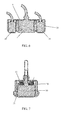
- a spring may be positioned between the cover and the encoder to exert a force against the encoder such that the sensing surface of the encoder is adjacent an opening in a corresponding surface of the housing so that it contacts or maintains an acceptable lift-off from the inspection surface to preserve position encoding even on slightly irregular surfaces.
- a recessed lip may be provided adjacent the opening to ensure that the encoder does not completely pass through the housing.
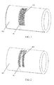
- the system is passed over the object surface so that the transducer can obtain structural data regarding the internal structure of the object.
- the encoder obtains position data regarding the position of the transducer (relative to the object) during the inspection.
- the structural and position data is captured and transmitted to additional equipment for processing.
- One aspect of this processing may be to provide real-time feedback to the system operator as to which portions of the object were inspected, ensuring that no portions of the intended inspection area were omitted.
- the system can provide feedback to the system operator regarding transducer skew relative to the desired orientation of the transducer.
- the encoded data may be displayed in a number of display modes including C-scan or terrain-map representations of the scan surface coupled with the NDE signal representing any flaws or anomalies observed within the scan area. Such displays may be analyzed to determine whether any defects are present in the object and to quantify any such defects as to location and size.
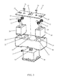
- FIG 3 shows an exploded view of a preferred inspection system 1, including a transducer 10.
- an ultrasound transducer is passed over the object being inspected.
- the transducer emits pulsed ultrasonic waves or electromagnetic waves that are imparted to the object.
- the waves pass into the object and are reflected back by any interface or material anomaly, such as the back wall of the object or from an imperfection within the object such as a crack, pit, eroded area, or a weld inclusion.
- the transducer receives the reflected waves and sends the received data to connected diagnostic equipment, such as an oscilloscope.
- these results typically are displayed in the form of a signal with an amplitude representing the intensity of the reflection and the arrival time of the reflection representing the distance (depth) to the reflecting interface.
- the coils generating the electromagnetic waves are sensed for changes in impedance or magnetic field strength.
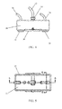
- FIGS 4 and 5 show front and top views, respectively, of the assembled inspection system 1.
- a housing 20 is provided with interior walls 22 defining an interior chamber 23 that is sized and configured to receive the transducer 10 such that the ultrasound transmitting and receiving elements are not inhibited.
- a cover plate 24 fits atop the housing and the transducer 10.
- the transducer 10 may be connected to its affiliated diagnostic equipment via wire bundle 12, which may be connected to the transducer via a connection 14.
- the cover plate 24 contains a central opening 25 sized and configured to fit around or under the connection 14, more preferably under a flange portion of the connection 14.
- Connectors 26, such as screw or bolts, may be provided to couple the cover plate 24 with the housing body 20 once they are in position.
- the connectors 26 cooperate with mating openings provided in the interior walls 22.
- An additional fastener 27 may be provided to cooperate with a mating opening in the housing of transducer 10 to couple the housing 20 and transducer 10.
- the interior wall 22 further defines a chamber 28 sized and configured to receive an optical encoder 30.
- a lip 21 or other retaining means may be provided on the lower edge of the housing 20 to prevent the encoder 30 from passing therethrough.
- the encoder 30 may communicate with it affiliated equipment via wire bundle 34. Alternatively, encoder 30 may be connected to its affiliated equipment wirelessly, obviating the need for wire bundle 34.
- the cover plate 24 preferably is provided with a side opening 29 to allow the wire bundle 34 (if present) to pass therethrough. Biasing members 32, such as springs, may be provided between the optical encoder 30 and the cover plate 24 to ensure the encoder is retained in the desired position at the lower portion of the housing 20 adj acent the UT transducer 10.
- the encoder 30 may be provided with a receptacle into which one end of the biasing member 32 is positioned. This is illustrated in Figures 6 , which shows a cross-sectional view of the inspection system 1 along line A-A of Figure 5 , and 7 , which shows a cross-sectional view of the inspection system 1 along line B-B of Figure 5 .
- the inspection system 1 includes two optical encoders 30, providing dual sources of position data.
- the system 1 is passed over or along the element to be inspected in the same manner as would the transducer 10 if used alone.
- the transducer 10 emits and receives ultrasound data, which is provided to additional equipment for processing and interpretation.
- the optical encoder(s) 30 measure and provide position data to be used in conjunction with the transducer data.
- the optical encoder 30 preferably includes a light to illuminate the surface of the element being inspected and an optoelectronic sensor to take successive images of the illuminated surface. The images are captured in continuous succession and compared with each other to determine how far the system 1 has moved. As many as one thousand successive images or more are captured every second. The images are processed using cross correlation to calculate how much each successive image is offset from the previous one, and therefore how far the system 1 has moved.
- the light may be provided in the form of a light-emitting diode (LED) or a laser diode.
- LED light-emitting diode
- the system 1 allows the operator to ensure that the entirety of the intended measurement area was in fact inspected.
- the data from the transducer 10 and optical encoder 30 are sent to processing equipment via wire bundles 12, 34 or wirelessly.
- processing equipment may take the form of a non-transitory computer system.
- the inspection and position data can be used a variety of ways.
- One way in which the position data can be used is to provide the operator of the inspection system 1 real-time feedback regarding the inspection process.
- the position information can be used to tell the operator which portions of the object under inspection have been examined.
- One preferred manner of doing this is to change the image of the object on the operator's display, such as by changing the color of the object on the display as it is examined. In this manner, the operator could ensure that data has been collected for the entirety of the area intended to be inspected.
- the operator can know that the full inspection has been performed or if there are unexamined areas remaining for inspection.
- the inspection and position data are linked such that an area of the object will be shown as having been inspected if the transducer 10 was passed over that area and inspection data was received. If for some reason the transducer 10 was not operational or inspection data was not received when the transducer 10 was passed over the area, then it should not be shown as having been inspected.
- the inspection and position data can also be stored for later examination. This allows skilled personnel to review and interpret the data at a convenient time and location. This minimizes the time required for the inspection system to remain in the environs of the object under inspection, inherently reducing time and expense related to having the inspection equipment in place.
- the system 1 thus allows fully encoded UT inspection data to be captured, stored, and displayed as though the scan was performed by an automated scanner without the setup difficulty or additional space required for a traditional automated scan system. Because the data is captured and stored, it may be analyzed and interpreted off-line in a comfortable environment. This allows the acquisition to be performed by relatively untrained inspectors, with the assurance that full measurements were made and subsequently the data may be interpreted by more highly qualified personnel.
- the system 1 can provide both absolute centroid position and transducer skew angle information. This provides assurance that the manual orientation of angle beam transducers is in fact aligned in accordance with the planned scan. Spacing of the encoders 30 is chosen as large as practical to reduce the error of the skew angle yet as small as practical to minimize the overall envelope of the transducer. Additionally, the two optical encoders allow redundant measurements to be correlated and used to detect and compensate anomalous position signals.
- This invention applies optical sensing technology with an UT inspection system to associate encoded position data with the inspection data.
- the compact electronics of the optical system can be attached to the UT transducer assembly to allow fully encoded position information to be associated with the UT data without substantially impacting the overall envelope of the UT transducer.
- the optical system can be used in tandem to monitor skew or twist of the transducers with respect to the normal rectilinear transducer orientation.
- the transducer's position information is then coupled to the UT data to provide cross-sectional view of the inspected equipment and data maps (B and C scan data outputs) equivalent to fully encoded multi-axis manipulator automated scans, but with less setup burden and equipment expense.
- This two dimensional surface encoding approach can be registered with a three dimensional model of the inspection object to allow full use of three dimensional modeling data interpretation algorithms and three dimensional projections of any reflections observed while preserving the easy setup and data acquisition associated with traditional manual UT or alternate NDE examinations.
- ROVs remotely operated vehicles
- SAFT synthetic aperture focusing techniques
- other data enhancements that rely heavily on precise positioning data cannot be used, whereas these types of data treatment are possible with the fully encoded feedback from the optical system 1.
- SAFT synthetic aperture focusing techniques
- independent free-motion manipulating devices may be controlled to move the transducers 10 to any region of interest without a fixed scanner or manipulator.
Landscapes
- Physics & Mathematics (AREA)
- General Physics & Mathematics (AREA)
- Engineering & Computer Science (AREA)
- Analytical Chemistry (AREA)
- Radar, Positioning & Navigation (AREA)
- Biochemistry (AREA)
- General Health & Medical Sciences (AREA)
- Life Sciences & Earth Sciences (AREA)
- Immunology (AREA)
- Pathology (AREA)
- Chemical & Material Sciences (AREA)
- Remote Sensing (AREA)
- Health & Medical Sciences (AREA)
- Acoustics & Sound (AREA)
- Computer Networks & Wireless Communication (AREA)
- Electromagnetism (AREA)
- Investigating Or Analyzing Materials By The Use Of Ultrasonic Waves (AREA)
Applications Claiming Priority (1)
| Application Number | Priority Date | Filing Date | Title |
|---|---|---|---|
| US13/731,580 US20140183341A1 (en) | 2012-12-31 | 2012-12-31 | Optical Encoded Nondestructive Inspection |
Publications (1)
| Publication Number | Publication Date |
|---|---|
| EP2749879A2 true EP2749879A2 (fr) | 2014-07-02 |
Family
ID=50064339
Family Applications (1)
| Application Number | Title | Priority Date | Filing Date |
|---|---|---|---|
| EP13197761.3A Withdrawn EP2749879A2 (fr) | 2012-12-31 | 2013-12-17 | Inspection non destructive codée optique |
Country Status (2)
| Country | Link |
|---|---|
| US (1) | US20140183341A1 (fr) |
| EP (1) | EP2749879A2 (fr) |
Cited By (3)
| Publication number | Priority date | Publication date | Assignee | Title |
|---|---|---|---|---|
| WO2016061319A1 (fr) * | 2014-10-17 | 2016-04-21 | Zetec, Inc. | Système d'affichage de région de test non-destructrice |
| EP3146326A4 (fr) * | 2014-05-23 | 2018-10-03 | Heigel Industrial Solutions Pty Ltd. | Dispositif et système de capture de données |
| GB2605989A (en) * | 2021-04-20 | 2022-10-26 | Garriga Casanovas Arnau | Device for simultaneous NDE measurement and localization for inspection scans of components |
Families Citing this family (4)
| Publication number | Priority date | Publication date | Assignee | Title |
|---|---|---|---|---|
| US9316619B2 (en) * | 2013-08-01 | 2016-04-19 | Siemens Energy, Inc. | Non destructive evaluation scanning probe with self-contained multi-axis position encoder |
| US10234269B2 (en) | 2015-06-11 | 2019-03-19 | Ge-Hitachi Nuclear Energy Americas Llc | Fiber optic shape sensing technology for encoding of NDE exams |
| CN111178523B (zh) * | 2019-08-02 | 2023-06-06 | 腾讯科技(深圳)有限公司 | 一种行为检测方法、装置、电子设备及存储介质 |
| CN110596151A (zh) * | 2019-08-16 | 2019-12-20 | 徐州远航模具有限公司 | 适用于模具探伤的设备 |
Family Cites Families (1)
| Publication number | Priority date | Publication date | Assignee | Title |
|---|---|---|---|---|
| GB9215346D0 (en) * | 1992-07-18 | 1992-09-02 | Rolls Royce & Ass | An apparatus for detecting defects |
-
2012
- 2012-12-31 US US13/731,580 patent/US20140183341A1/en not_active Abandoned
-
2013
- 2013-12-17 EP EP13197761.3A patent/EP2749879A2/fr not_active Withdrawn
Non-Patent Citations (1)
| Title |
|---|
| None |
Cited By (4)
| Publication number | Priority date | Publication date | Assignee | Title |
|---|---|---|---|---|
| EP3146326A4 (fr) * | 2014-05-23 | 2018-10-03 | Heigel Industrial Solutions Pty Ltd. | Dispositif et système de capture de données |
| WO2016061319A1 (fr) * | 2014-10-17 | 2016-04-21 | Zetec, Inc. | Système d'affichage de région de test non-destructrice |
| US10295503B2 (en) | 2014-10-17 | 2019-05-21 | Zetec, Inc. | System for display of non-destructive testing region |
| GB2605989A (en) * | 2021-04-20 | 2022-10-26 | Garriga Casanovas Arnau | Device for simultaneous NDE measurement and localization for inspection scans of components |
Also Published As
| Publication number | Publication date |
|---|---|
| US20140183341A1 (en) | 2014-07-03 |
Similar Documents
| Publication | Publication Date | Title |
|---|---|---|
| EP2749879A2 (fr) | Inspection non destructive codée optique | |
| US8616062B2 (en) | Ultrasonic inspection system and ultrasonic inspection method | |
| US6925145B2 (en) | High speed digital radiographic inspection of piping | |
| KR101408466B1 (ko) | 원자로 스터드 자동 초음파검사 장치 및 방법 | |
| WO2011138741A1 (fr) | Inspection d'objets par capteur d'analyse volumétrique de référence | |
| EP3104173A1 (fr) | Technique de détection de forme de fibre optique pour coder des examens nde | |
| EP2749878A2 (fr) | Inspection ultrasonore codée de vision stéréo | |
| JP2011027571A (ja) | 配管減肉検査装置および配管減肉検査方法 | |
| JP2012247262A (ja) | 超音波探傷方法及び超音波探傷装置 | |
| Xu et al. | Data fusion of multi-view plane wave imaging for nozzle weld inspection | |
| US6122967A (en) | Free motion scanning system | |
| US9625421B2 (en) | Manually operated small envelope scanner system | |
| EP3236255A1 (fr) | Appareil et procédé permettant d'observer une partie d'un tube soudé par aboutement | |
| KR200499206Y1 (ko) | 협동 로봇을 이용한 초음파 탐상 검측 장치 | |
| US20130088707A1 (en) | Method and system for crack detection | |
| Morozov et al. | Robotic ultrasonic testing of AGR fuel cladding | |
| JP4676300B2 (ja) | Rt3次元サイジング装置 | |
| Xi et al. | Preliminary Study on Endoscopic Ultrasound System for In-Service Inspection of Helical Tube Once-Through Steam Generator | |
| JP3787347B2 (ja) | 伝熱管群検査装置 | |
| JP5422463B2 (ja) | 原子炉圧力容器下鏡部における非破壊検査手法 | |
| Cinson et al. | Comparison of an ultrasonic phased array evaluation with destructive analysis of a documented leak path in a nozzle removed from service | |
| JP2025073840A (ja) | 非破壊検査システム及び非破壊検査方法 | |
| PIRON et al. | Innovation in 3D scanning technology and software is pushing the limits of complex corrosion and mechanical damage assessment on pipelines. | |
| Collingwood | Nuclear NDT development at Harwell | |
| Bennecer | Reliability of manual ultrasonic testing |
Legal Events
| Date | Code | Title | Description |
|---|---|---|---|
| 17P | Request for examination filed |
Effective date: 20131217 |
|
| AK | Designated contracting states |
Kind code of ref document: A2 Designated state(s): AL AT BE BG CH CY CZ DE DK EE ES FI FR GB GR HR HU IE IS IT LI LT LU LV MC MK MT NL NO PL PT RO RS SE SI SK SM TR |
|
| AX | Request for extension of the european patent |
Extension state: BA ME |
|
| PUAI | Public reference made under article 153(3) epc to a published international application that has entered the european phase |
Free format text: ORIGINAL CODE: 0009012 |
|
| RAP1 | Party data changed (applicant data changed or rights of an application transferred) |
Owner name: AREVA INC. |
|
| STAA | Information on the status of an ep patent application or granted ep patent |
Free format text: STATUS: THE APPLICATION IS DEEMED TO BE WITHDRAWN |
|
| 18D | Application deemed to be withdrawn |
Effective date: 20160701 |