EP2752673A1 - Méthode et dispositif de mesure de courant - Google Patents
Méthode et dispositif de mesure de courant Download PDFInfo
- Publication number
- EP2752673A1 EP2752673A1 EP13798536.2A EP13798536A EP2752673A1 EP 2752673 A1 EP2752673 A1 EP 2752673A1 EP 13798536 A EP13798536 A EP 13798536A EP 2752673 A1 EP2752673 A1 EP 2752673A1
- Authority
- EP
- European Patent Office
- Prior art keywords
- sampling point
- signal
- temperature
- voltage
- sampling
- Prior art date
- Legal status (The legal status is an assumption and is not a legal conclusion. Google has not performed a legal analysis and makes no representation as to the accuracy of the status listed.)
- Withdrawn
Links
Images


Classifications
-
- G—PHYSICS
- G01—MEASURING; TESTING
- G01R—MEASURING ELECTRIC VARIABLES; MEASURING MAGNETIC VARIABLES
- G01R19/00—Arrangements for measuring currents or voltages or for indicating presence or sign thereof
- G01R19/25—Arrangements for measuring currents or voltages or for indicating presence or sign thereof using digital measurement techniques
-
- G—PHYSICS
- G01—MEASURING; TESTING
- G01R—MEASURING ELECTRIC VARIABLES; MEASURING MAGNETIC VARIABLES
- G01R1/00—Details of instruments or arrangements of the types included in groups G01R5/00 - G01R13/00 and G01R31/00
- G01R1/20—Modifications of basic electric elements for use in electric measuring instruments; Structural combinations of such elements with such instruments
- G01R1/203—Resistors used for electric measuring, e.g. decade resistors standards, resistors for comparators, series resistors, shunts
-
- G—PHYSICS
- G01—MEASURING; TESTING
- G01R—MEASURING ELECTRIC VARIABLES; MEASURING MAGNETIC VARIABLES
- G01R19/00—Arrangements for measuring currents or voltages or for indicating presence or sign thereof
- G01R19/0092—Measuring current only
-
- H—ELECTRICITY
- H01—ELECTRIC ELEMENTS
- H01M—PROCESSES OR MEANS, e.g. BATTERIES, FOR THE DIRECT CONVERSION OF CHEMICAL ENERGY INTO ELECTRICAL ENERGY
- H01M10/00—Secondary cells; Manufacture thereof
- H01M10/42—Methods or arrangements for servicing or maintenance of secondary cells or secondary half-cells
- H01M10/48—Accumulators combined with arrangements for measuring, testing or indicating the condition of cells, e.g. the level or density of the electrolyte
- H01M10/486—Accumulators combined with arrangements for measuring, testing or indicating the condition of cells, e.g. the level or density of the electrolyte for measuring temperature
-
- Y—GENERAL TAGGING OF NEW TECHNOLOGICAL DEVELOPMENTS; GENERAL TAGGING OF CROSS-SECTIONAL TECHNOLOGIES SPANNING OVER SEVERAL SECTIONS OF THE IPC; TECHNICAL SUBJECTS COVERED BY FORMER USPC CROSS-REFERENCE ART COLLECTIONS [XRACs] AND DIGESTS
- Y02—TECHNOLOGIES OR APPLICATIONS FOR MITIGATION OR ADAPTATION AGAINST CLIMATE CHANGE
- Y02E—REDUCTION OF GREENHOUSE GAS [GHG] EMISSIONS, RELATED TO ENERGY GENERATION, TRANSMISSION OR DISTRIBUTION
- Y02E60/00—Enabling technologies; Technologies with a potential or indirect contribution to GHG emissions mitigation
- Y02E60/10—Energy storage using batteries
Definitions
- the present invention relates to the field of electronic technologies, and in particular, to a method and a device for measuring a current.
- a communication power supply is usually called the heart of a communication system. If the communication power supply works abnormally, a communication system fault may occur, and the whole system may even fail.
- a current diverter is used mostly to detect the current of a communication power supply.
- the current diverter When being used to perform sampling detection on the current, the current diverter is equivalent to a resistor with a small temperature drift coefficient. Therefore, it is obtained from the Ohm's law that, the voltage is proportional to the current, and the value of the current passing through the current diverter is calculated proportionally by obtaining the voltage values at both ends of the current diverter.
- the current diverter uses the current diverter to perform sampling detection on the current to perform sampling detection on the current has some inevitable defects. Because the current diverter has a large resistance value, when the current passing through the current diverter is 1000 A, a corresponding voltage drop of 75 MV is generated at the current diverter, and at this time, the power consumption of the current diverter is 75 W. Therefore, the power consumption of the current diverter is large. Because the large power consumption causes the temperature value of the current diverter to rise, and the resistance of the current diverter may change with the temperature, the stability of the current diverter is reduced. In addition, the cost of manufacturing the current diverter is relatively high.
- Embodiments of the present invention disclose a method and a device for measuring a current, so as to reduce power consumption during the process of current sampling detection, and improve the stability of the current detection.
- an embodiment of the present invention provides a method for measuring a current, including: measuring a temperature between a first sampling point and a second sampling point on a copper bar carrying a current to be measured, and outputting a first signal according to the measured temperature; outputting a second signal after sampling and filtering the first signal; detecting a first voltage signal at the first sampling point and a second voltage signal at the second sampling point, sampling and filtering a signal difference between the first voltage signal and the second voltage signal, and outputting a third voltage signal; converting the second signal into a first digital signal, restoring, according to the first digital signal, the second signal to a temperature value representing a temperature between the first sampling point and the second sampling point, and calculating a resistance value between the first sampling point and the second sampling point according to the temperature value; converting the third voltage signal into a second digital signal, and restoring, according to the second digital signal, the third voltage signal to a voltage value representing a voltage between the first sampling point and the second sampling point; and calculating, according to
- the calculating a resistance value between the first sampling point and the second sampling point according to the temperature value specifically includes:
- the copper bar between the first sampling point and the second sampling point has multiple holes and/or multiple apertures, so as to decrease the area of the copper bar to increase the resistance value of the copper bar.
- an embodiment of the present invention provides a device for measuring a current, where the device includes:
- the controller is specifically configured to: calculate the resistance value between the first sampling point and the second sampling point and corresponding to the temperature value, by using a resistance-temperature comparison table or a resistance-temperature formula.
- the analog-digital converter is integrated inside the controller; or the analog-digital converter is integrated outside the controller.
- the copper bar has multiple holes and/or multiple apertures, so as to decrease the area of the copper bar to increase the resistance value of the copper bar.
- the temperature sensor measures the temperature at any point between the sampling points on the copper bar
- the controller converts the signal output by the temperature sensor into the temperature value and the resistance value of the sampling points on the copper bar, and indirectly measures the value of a current passing through the sampling points by using the resistance value and the voltage value of the sampling points.
- multiple holes or apertures are arranged on the copper bar, which indirectly increases the resistance of the copper bar and reduces current power consumption, so as to lower the temperature of the copper bar, thereby improving the stability of a measuring system.
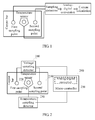
- FIG. 1 is a structural diagram of measuring a current according to an embodiment of the present invention.
- a temperature and a voltage between a first sampling point and a second sampling point are measured; the measured temperature between the first sampling point and the second sampling point undergoes sampling detection and analog-digital conversion, and then is converted into a resistance value between the first sampling point and the second sampling point; the measured voltage between the first sampling point and the second sampling point undergoes sampling detection and analog-digital conversion, and then is converted into a voltage value between the first sampling point and the second sampling point; and the value of a current between the first sampling point and the second sampling point on a copper bar is calculated by using the resistance value and the voltage value between the first sampling point and the second sampling point.
- FIG. 2 is a diagram of a device for measuring a current according to an embodiment of the present invention.
- the device includes a copper bar 210, a temperature sensor 220, a temperature sampling detector 230, a voltage sampling detector 240, an analog-digital converter 250, and a controller 260.
- Two sampling points that is, a first sampling point and a second sampling point, are selected on the copper bar 210.
- the two sampling points are secured by using a screw (or a buckle).
- the first sampling point and the second sampling point are connected to the voltage sampling detector 240.
- the temperature sensor 220 is placed between the two sampling points, and is also secured by using a screw (or a buckle).
- the temperature sensor 220 is connected to the temperature sampling detector 230.
- the temperature sampling detector 230 and the voltage sampling detector 240 are connected to the controller 260, where the analog-digital converter 250 may be integrated inside the controller 260; or the analog-digital converter is integrated outside the controller 260, that is, the analog-digital converter 250 is deployed separately. In this embodiment of the present invention, integrating the analog-digital converter 250 inside the controller 260 is taken as an example.
- the copper bar 210 in the device is configured to carry a current to be measured.
- the temperature sensor 220 is configured to measure a temperature between the first sampling point and the second sampling point located on the copper bar, and output a first signal according to the measured temperature.
- the temperature sensor 220 is placed between the two sampling points, and is secured by using a screw (or a buckle). The temperature sensor 220 measures the temperature at any point between the two sampling points. After the copper bar is fed with a direct current or an alternating current, the temperature sensor 220 starts to operate, and measures the temperature at any point between the first sampling point and the second sampling point.
- the temperature sensor 220 has various types. In practical applications, other types of temperature sensors can be used, for example, an integrated temperature sensor which has an analog-digital conversion integrated inside and provides digital bus communication externally; a current-type temperature sensor, where the signal output by the sensor is a current signal which is converted into a voltage signal after being sampled and detected; a voltage-type temperature sensor, where the signal output by the sensor is a voltage signal.
- any type of temperature sensor may operate normally when a direct current or an alternating current passes through it.
- a thermistor-type temperature sensor is taken as an example, and the temperature sensor outputs a voltage signal.
- the temperature sensor is a thermistor-type temperature sensor, and the temperature sensor outputs a voltage signal, where the voltage signal represents a temperature value at any point between the sampling points.
- the temperature sensor 220 is fed with an external power supply or an internal power supply.
- the temperature sampling detector 230 is configured to receive the first signal output by the temperature sensor, and output a second signal after sampling and filtering the first signal.
- the temperature sampling detector 230 samples, filters, and proportionally scales the first signal, and outputs a second signal after the processing.
- the voltage sampling detector 240 is configured to detect a first voltage signal at the first sampling point located on the copper bar and a second voltage signal at the second sampling point located on the copper bar, sample and filter a signal difference between the first voltage signal and the second voltage signal, and output a third voltage signal.
- the voltage sampling detection circuit 240 is connected to the first sampling point and the second sampling point on the copper bar, and detects the first voltage signal at the first sampling point and the second voltage signal at the second sampling point, obtains the signal difference between the first voltage signal and the second voltage signal, samples, filters, and proportionally scales the signal difference of the sampling points, and outputs a third voltage signal after the processing.
- selected temperature sensors 220 may be different in type, the first signals output by the temperature sensors 220 are different.
- a temperature sensor 220 outputs a voltage signal
- the first signal represents the temperature between the first sampling point and the second sampling point
- the first voltage signal and the second voltage signal represent voltages generated by the first sampling point and the second sampling point respectively when a current passes through.
- the analog-digital converter 250 is configured to: receive the second signal output by the temperature sampling detector, convert the second signal into a first digital signal, and output the first digital signal; and receive the third voltage signal output by the voltage sampling detector, convert the third voltage signal into a second digital signal, and output the second digital signal.
- the controller 260 is configured to: receive the first digital signal and the second digital signal output by the analog-digital converter, restore, according to the first digital signal, the second signal to a temperature value representing a temperature between the first sampling point and the second sampling point, and calculate a resistance value between the first sampling point and the second sampling point according to the temperature value; and restore, according to the second digital signal, the third voltage signal to a voltage value representing a voltage between the first sampling point and the second sampling point, and calculate, according to the voltage value and the resistance value, the value of a current between the first sampling point and the second sampling point.
- the controller 260 receives the first digital signal obtained after the processing performed by the analog-digital converter 250, restores the first digital signal to a temperature value representing a temperature between the first sampling point and the second sampling point. Then the controller 260 invokes a self-stored resistance-temperature comparison table or a resistance-temperature formula, and calculates the resistance value between the first sampling point and the second temperature value according to the temperature value.
- the controller 260 further receives the second digital signal obtained after the processing performed by the analog-digital converter 250, and restores the second digital signal to a voltage value representing a voltage between the first sampling point and the second sampling point.
- the controller 260 calculates the value of a current between the first sampling point and the second sampling point by using the voltage value and the resistance value.
- the analog-digital converter 250 is integrated outside the controller 260, that is, when the analog-digital converter 250 is deployed separately, the device may further include: a first analog-digital converter 310 and a second analog-digital converter 320.
- the first analog-digital converter 310 is connected to the temperature sampling detector 230, and is configured to receive the second signal, convert the second signal into a first digital signal, and transmit the first digital signal to the controller 260.
- the second analog-digital converter 320 is connected to the voltage sampling detector 240, and is configured to receive the third voltage signal, convert the third voltage signal into a second digital signal, and transmit the second digital signal to the controller 260.
- the analog-digital converter 250 is integrated inside the controller 260, meanwhile the first analog-digital converter 310 or second analog-digital converter 320 may be added to the device alternatively, so as to simplify the work load of the controller, improve the arithmetic speed of the controller, and enhance analog-digital conversion precision.
- the analog-digital converter 250 is integrated inside the controller 260, the first analog-digital converter 310 may be alternatively added.
- the first analog-digital converter 310 is connected to the temperature sampling detector 230, the first analog-digital converter 310 receives the second signal, converts the second signal into a first digital signal, and directly transmits the first digital signal to the controller 260.
- the controller 260 is further connected to the voltage sampling detector 240.
- the voltage sampling detector 240 directly transmits the third voltage signal to the controller 260; and the controller 260 converts the third voltage signal into a second digital signal by using the built-in integrated analog-digital converter 250, and converts the second digital signal into the voltage value between the sampling points.
- the analog-digital converter 250 is integrated inside the controller 260, and the second analog-digital converter 320 may be alternatively added.
- the second analog-digital converter 320 is connected to the voltage sampling detector 240; and the second analog-digital converter 320 receives the third voltage signal, converts the third voltage signal into a second digital signal, and directly transmits the second digital signal to the controller 260.
- the controller 260 is further connected to the temperature sampling detector 230.
- the temperature sampling detector 230 directly transmits the second signal to the controller 260.
- the controller 260 converts the second signal into a first digital signal by using the built-in integrated analog-digital converter 250, converts the first digital signal into the temperature value between the sampling points, and further calculates the resistance value between the sampling points.
- FIG. 4-C shows another form of a device for measuring a current.
- the temperature sampling detector 230 is replaced by a digital communication bus.
- the integrated temperature sensor converts the measured temperature into a digital signal, and communicates with an on-chip peripheral bus corresponding to the controller 260 by using a digital bus interface such as I2C, onewire, SPI, or the like.
- the controller 260 reads, through the on-chip peripheral bus, the digital signal sampled by the integrated temperature sensor, and converts the digital signal into the temperature value between the first sampling point and the second sampling point.
- the device further includes a power supply, which is not shown in the figure.
- the power supply loads a direct current or an alternating current for the copper bar 210.
- each component in the device for measuring a current is described by taking an example that the power supply loads a direct current. In practical applications, the power supply may also load an alternating current.
- an alternating current is loaded, functions of the components in the device for measuring a current are the same, which are not described herein again.
- the voltage sampling detector 240 and/or second analog-digital converter 320 should be isolated, to reduce the electrical interference of the two components on other components.
- multiple holes and/or apertures may be further arranged on the copper bar 210 in the embodiment of the present invention, to increase the resistance value of the copper bar 210, reduce the current passing through the copper bar 210, and indirectly reduce the power consumption.
- the sectional area of the copper bar 210 is decreased to reduce the heat emitted by the copper bar 210, as shown in FIG. 5-A, FIG. 5-B, and FIG. 5-C .
- the manner of decreasing the sectional area of the copper bar is not limited to the three types shown in FIG. 5-A, FIG. 5-B, and FIG. 5-C .
- the temperature sensor measures the temperature at any point between the sampling points on the copper bar; the controller converts the signal output by the temperature sensor into the temperature value and the resistance value of the sampling points on the copper bar, and indirectly measures the value of the current passing through the sampling points by using the resistance value and the voltage value of the sampling points.
- multiple holes or apertures are arranged on the copper bar, which indirectly increases the resistance of the copper bar and reduces current power consumption, so as to lower the temperature of the copper bar, thereby improving the stability of a measuring system.
- FIG. 6 is a flowchart of a method for measuring a current according to an embodiment of the present invention.
- the method shown in FIG. 6 is implemented based on the aforementioned device embodiment. Based on the device for measuring a current, the method for measuring a current specifically includes the following steps:
- Step 610 Measure a temperature between a first sampling point and a second sampling point on a copper bar carrying a current to be measured, and output a first signal according to the measured temperature.
- two sampling points that is, a first sampling point and a second sampling point
- the two sampling points are secured by using a screw (or a buckle).
- a direct current or an alternating current is provided, the temperature at any point between the two sampling points is measured.
- the first signal is output according to the measured temperature.
- the current to be measured is carried on the copper bar.
- Step 620 Output a second signal after the first signal is sampled and filtered.
- the first signal is sampled, filtered, and proportionally scaled, and a second signal is output after the processing.
- Step 630 Detect a first voltage signal at the first sampling point and a second voltage signal at the second sampling point, sample and filter a signal difference between the first voltage signal and the second voltage signal, and output a third voltage signal.
- the copper bar is fed with a direct current or an alternating current, voltages appears at the first sampling point and the second sampling point on the copper bar.
- the first voltage signal at the first sampling point and the second voltage signal at the second sampling point are detected, the signal difference between the first voltage signal and the second voltage signal is obtained, the signal difference is sampled, filtered, and proportionally scaled, and a third voltage signal is output after the processing.
- Step 640 Convert the second signal into a first digital signal, restore, according to the first digital signal, the second signal to a temperature value representing a temperature between the first sampling point and the second sampling point, and calculate a resistance value between the first sampling point and the second sampling point according to the temperature value.
- the second signal is converted into the first digital signal
- the first digital signal is converted into the value representing a temperature between the first sampling point and the second sampling point
- a resistance-temperature comparison table or a resistance-temperature formula is invoked, and the resistance value between the first sampling point and the second sampling point at the temperature value is calculated.
- Step 650 Convert the third voltage signal into a second digital signal, and restore, according to the second digital signal, the third voltage signal to a voltage value representing a voltage between the first sampling point and the second sampling point.
- the third voltage signal is converted into a second digital signal
- the second digital signal is converted into the voltage value representing the voltage between the first sampling point and the second sampling point.
- Step 660 Calculate, according to the voltage value and the resistance value, the value of a current between the first sampling point and the second sampling point.
- the value of the current between the first sampling point and the second sampling point is calculated according to the resistance value obtained in step 640 and the voltage value obtained in step 650 by using the Ohm's law.
- multiple holes and/or apertures may be further arranged on the copper bar in the embodiments of the present invention, to increase the resistance value of the copper bar, reduce the current passing through the copper bar, and indirectly reduce the power consumption.
- the sectional area of the copper bar is decreased to reduce the heat emitted by the copper bar, as shown in FIG. 5-A, FIG. 5-B, and FIG. 5-C .
- the manner of decreasing the sectional area of the copper bar is not limited to the three types shown in FIG. 5-A, FIG. 5-B, and FIG. 5-C .
- the temperature at any point between the sampling points on the copper bar is measured; the signal representing the temperature is converted into the temperature value and the resistance value of the sampling points on the copper bar; and the value of the current passing through the sampling points is calculated indirectly by using the resistance value and the voltage value of the sampling points.
- multiple holes or apertures are arranged on the copper bar, which indirectly increases the resistance of the copper bar, so as to lower the temperature of the copper bar, thereby improving the stability of a measuring system.
Landscapes
- Physics & Mathematics (AREA)
- General Physics & Mathematics (AREA)
- Measurement Of Current Or Voltage (AREA)
Applications Claiming Priority (2)
| Application Number | Priority Date | Filing Date | Title |
|---|---|---|---|
| CN201210426192.3A CN102928657B (zh) | 2012-10-31 | 2012-10-31 | 测量电流的方法与装置 |
| PCT/CN2013/073877 WO2014067259A1 (fr) | 2012-10-31 | 2013-04-08 | Méthode et dispositif de mesure de courant |
Publications (2)
| Publication Number | Publication Date |
|---|---|
| EP2752673A1 true EP2752673A1 (fr) | 2014-07-09 |
| EP2752673A4 EP2752673A4 (fr) | 2014-07-30 |
Family
ID=47643503
Family Applications (1)
| Application Number | Title | Priority Date | Filing Date |
|---|---|---|---|
| EP20130798536 Withdrawn EP2752673A4 (fr) | 2012-10-31 | 2013-04-08 | Méthode et dispositif de mesure de courant |
Country Status (3)
| Country | Link |
|---|---|
| EP (1) | EP2752673A4 (fr) |
| CN (1) | CN102928657B (fr) |
| WO (1) | WO2014067259A1 (fr) |
Families Citing this family (11)
| Publication number | Priority date | Publication date | Assignee | Title |
|---|---|---|---|---|
| CN102928657B (zh) * | 2012-10-31 | 2015-07-22 | 华为技术有限公司 | 测量电流的方法与装置 |
| US9482696B2 (en) | 2012-10-31 | 2016-11-01 | Huawei Technologies Co., Ltd. | Method and device for measuring current |
| CN104849665B (zh) * | 2014-02-19 | 2018-01-30 | 中国移动通信集团河北有限公司 | 一种确定蓄电池安全放电时长的方法及装置 |
| CN104215821B (zh) * | 2014-09-18 | 2017-02-01 | 青岛歌尔声学科技有限公司 | 一种电源设备输入浪涌电流检测方法 |
| US9823154B2 (en) * | 2014-11-12 | 2017-11-21 | Kidde Technologies, Inc. | Bleed air duct leak system real-time fault detection |
| CN108226646B (zh) * | 2018-01-17 | 2022-02-22 | 珠海极海半导体有限公司 | 敏感电阻测量装置及测量方法 |
| CN108809193A (zh) * | 2018-05-24 | 2018-11-13 | 北京交通大学 | 一种适用于地铁变流器的感应电机电阻辨识方法 |
| CN111965554B (zh) * | 2020-07-31 | 2023-05-30 | 蜂巢能源科技股份有限公司 | 电池包中铜排连接检测方法、装置、存储介质及电子设备 |
| CN112874378B (zh) * | 2021-01-27 | 2022-12-09 | 一汽解放汽车有限公司 | 一种电池采样温度的处理方法、装置、设备及车辆 |
| CN221765567U (zh) * | 2023-09-08 | 2024-09-24 | 宁德时代新能源科技股份有限公司 | 分流器模组、电流采集系统、电路及车辆 |
| CN117554677B (zh) * | 2024-01-11 | 2024-04-23 | 武汉嘉晨电子技术有限公司 | 一种电流传感器 |
Family Cites Families (6)
| Publication number | Priority date | Publication date | Assignee | Title |
|---|---|---|---|---|
| FR2802302B1 (fr) * | 1999-12-09 | 2002-02-15 | Sagem | Appareil de mesure de l'intensite du courant dans un conducteur |
| US7173429B2 (en) * | 2003-12-12 | 2007-02-06 | Power Designers, Llc | Activity-based battery monitor with a universal current measuring apparatus |
| DE102004042719A1 (de) * | 2004-09-03 | 2005-09-29 | Audi Ag | Stromsensor mit einem Messwiderstand |
| KR100971343B1 (ko) * | 2007-09-28 | 2010-07-20 | 삼성에스디아이 주식회사 | 온도보상 전류측정 장치를 이용한 배터리팩 |
| CN101650408B (zh) * | 2008-08-12 | 2011-11-30 | 华为技术有限公司 | 一种检测集成电路负载在线功耗的方法、装置和设备 |
| CN102928657B (zh) * | 2012-10-31 | 2015-07-22 | 华为技术有限公司 | 测量电流的方法与装置 |
-
2012
- 2012-10-31 CN CN201210426192.3A patent/CN102928657B/zh active Active
-
2013
- 2013-04-08 WO PCT/CN2013/073877 patent/WO2014067259A1/fr not_active Ceased
- 2013-04-08 EP EP20130798536 patent/EP2752673A4/fr not_active Withdrawn
Also Published As
| Publication number | Publication date |
|---|---|
| WO2014067259A1 (fr) | 2014-05-08 |
| EP2752673A4 (fr) | 2014-07-30 |
| CN102928657B (zh) | 2015-07-22 |
| CN102928657A (zh) | 2013-02-13 |
Similar Documents
| Publication | Publication Date | Title |
|---|---|---|
| EP2752673A1 (fr) | Méthode et dispositif de mesure de courant | |
| EP2413148B1 (fr) | Circuit de mesure de la résistance d'isolement non influencé par la tension de batterie | |
| CN101140317B (zh) | 电池组总电压检测和漏泄检测装置 | |
| CN108501757B (zh) | 一种电池管理系统、电流采样方法、装置及电动汽车 | |
| US20160054370A1 (en) | Ground fault detection based on capacitive sensing | |
| EP3203597A1 (fr) | Dispositif et procédé de détection de sécurité d'un onduleur raccordé au réseau électrique | |
| JP2015527044A (ja) | 入力電力及び電流測定のシステム及び方法 | |
| CN206515387U (zh) | 电流检测装置及电流检测系统 | |
| CN203705533U (zh) | 电动汽车霍尔电流传感器电流检测电路 | |
| WO2018107987A1 (fr) | Dispositif de détection de courant, système de détection de courant et procédé de détection de courant | |
| CN111880104B (zh) | 检测电路及方法、检测器、电池装置、运输工具与计算机可读存储介质 | |
| KR101925629B1 (ko) | 홀 센서를 이용한 지능형 배터리 센서 장치 | |
| WO2021114513A1 (fr) | Capteur de courant de qualité automobile et son procédé de détection | |
| US20240369666A1 (en) | Method of self-calibration current sensor | |
| KR20220125099A (ko) | 기생 인덕턴스 기반 스위칭전류 측정에서의 온도 영향 저감 장치 및 방법 | |
| JP6029340B2 (ja) | 直流配電盤システム | |
| US20170288439A1 (en) | Signal processing circuit, coulomb counter circuit, and electronic device | |
| US9482696B2 (en) | Method and device for measuring current | |
| EP2767839B1 (fr) | Détecteur de valeur quadratique moyenne et disjoncteur utilisant celui-ci | |
| CN103376354B (zh) | 测量电源产生的功率的系统和方法 | |
| JP2020204524A (ja) | 電流センサ及び測定装置 | |
| CN114720889A (zh) | 应用于电池管理系统的同步监测电路和同步监测方法 | |
| AU2014204547A1 (en) | Identifying defective electrical cables | |
| CN103217570A (zh) | Tmr自温补数字电流传感器 | |
| CN109752593B (zh) | 检测系统和电能计量芯片及其设备 |
Legal Events
| Date | Code | Title | Description |
|---|---|---|---|
| PUAI | Public reference made under article 153(3) epc to a published international application that has entered the european phase |
Free format text: ORIGINAL CODE: 0009012 |
|
| 17P | Request for examination filed |
Effective date: 20131209 |
|
| AK | Designated contracting states |
Kind code of ref document: A1 Designated state(s): AL AT BE BG CH CY CZ DE DK EE ES FI FR GB GR HR HU IE IS IT LI LT LU LV MC MK MT NL NO PL PT RO RS SE SI SK SM TR |
|
| A4 | Supplementary search report drawn up and despatched |
Effective date: 20140630 |
|
| RIC1 | Information provided on ipc code assigned before grant |
Ipc: G01R 31/36 20060101ALI20140624BHEP Ipc: G01R 19/25 20060101AFI20140624BHEP |
|
| 17Q | First examination report despatched |
Effective date: 20150513 |
|
| STAA | Information on the status of an ep patent application or granted ep patent |
Free format text: STATUS: THE APPLICATION IS DEEMED TO BE WITHDRAWN |
|
| DAX | Request for extension of the european patent (deleted) | ||
| 18D | Application deemed to be withdrawn |
Effective date: 20150924 |