EP2752702A1 - Kollimator und laserlichtquelle - Google Patents
Kollimator und laserlichtquelle Download PDFInfo
- Publication number
- EP2752702A1 EP2752702A1 EP12827409.9A EP12827409A EP2752702A1 EP 2752702 A1 EP2752702 A1 EP 2752702A1 EP 12827409 A EP12827409 A EP 12827409A EP 2752702 A1 EP2752702 A1 EP 2752702A1
- Authority
- EP
- European Patent Office
- Prior art keywords
- collimating lens
- lens
- laser
- laser beam
- light source
- Prior art date
- Legal status (The legal status is an assumption and is not a legal conclusion. Google has not performed a legal analysis and makes no representation as to the accuracy of the status listed.)
- Withdrawn
Links
- 238000001228 spectrum Methods 0.000 claims abstract description 12
- 239000013307 optical fiber Substances 0.000 claims description 45
- 230000003247 decreasing effect Effects 0.000 abstract 1
- 210000001624 hip Anatomy 0.000 description 27
- 230000001419 dependent effect Effects 0.000 description 10
- 230000004075 alteration Effects 0.000 description 6
- 239000000835 fiber Substances 0.000 description 5
- 238000010586 diagram Methods 0.000 description 4
- 230000003287 optical effect Effects 0.000 description 4
- 230000007423 decrease Effects 0.000 description 3
- 238000005516 engineering process Methods 0.000 description 2
- 238000005253 cladding Methods 0.000 description 1
- 230000000694 effects Effects 0.000 description 1
- 239000011521 glass Substances 0.000 description 1
- 238000011835 investigation Methods 0.000 description 1
- 230000001902 propagating effect Effects 0.000 description 1
- 239000000758 substrate Substances 0.000 description 1
Images




Classifications
-
- G—PHYSICS
- G02—OPTICS
- G02B—OPTICAL ELEMENTS, SYSTEMS OR APPARATUS
- G02B27/00—Optical systems or apparatus not provided for by any of the groups G02B1/00 - G02B26/00, G02B30/00
- G02B27/30—Collimators
-
- B—PERFORMING OPERATIONS; TRANSPORTING
- B23—MACHINE TOOLS; METAL-WORKING NOT OTHERWISE PROVIDED FOR
- B23K—SOLDERING OR UNSOLDERING; WELDING; CLADDING OR PLATING BY SOLDERING OR WELDING; CUTTING BY APPLYING HEAT LOCALLY, e.g. FLAME CUTTING; WORKING BY LASER BEAM
- B23K26/00—Working by laser beam, e.g. welding, cutting or boring
- B23K26/02—Positioning or observing the workpiece, e.g. with respect to the point of impact; Aligning, aiming or focusing the laser beam
- B23K26/06—Shaping the laser beam, e.g. by masks or multi-focusing
- B23K26/064—Shaping the laser beam, e.g. by masks or multi-focusing by means of optical elements, e.g. lenses, mirrors or prisms
- B23K26/0648—Shaping the laser beam, e.g. by masks or multi-focusing by means of optical elements, e.g. lenses, mirrors or prisms comprising lenses
-
- B—PERFORMING OPERATIONS; TRANSPORTING
- B23—MACHINE TOOLS; METAL-WORKING NOT OTHERWISE PROVIDED FOR
- B23K—SOLDERING OR UNSOLDERING; WELDING; CLADDING OR PLATING BY SOLDERING OR WELDING; CUTTING BY APPLYING HEAT LOCALLY, e.g. FLAME CUTTING; WORKING BY LASER BEAM
- B23K26/00—Working by laser beam, e.g. welding, cutting or boring
- B23K26/02—Positioning or observing the workpiece, e.g. with respect to the point of impact; Aligning, aiming or focusing the laser beam
- B23K26/06—Shaping the laser beam, e.g. by masks or multi-focusing
- B23K26/064—Shaping the laser beam, e.g. by masks or multi-focusing by means of optical elements, e.g. lenses, mirrors or prisms
- B23K26/066—Shaping the laser beam, e.g. by masks or multi-focusing by means of optical elements, e.g. lenses, mirrors or prisms by using masks
-
- B—PERFORMING OPERATIONS; TRANSPORTING
- B23—MACHINE TOOLS; METAL-WORKING NOT OTHERWISE PROVIDED FOR
- B23K—SOLDERING OR UNSOLDERING; WELDING; CLADDING OR PLATING BY SOLDERING OR WELDING; CUTTING BY APPLYING HEAT LOCALLY, e.g. FLAME CUTTING; WORKING BY LASER BEAM
- B23K26/00—Working by laser beam, e.g. welding, cutting or boring
- B23K26/02—Positioning or observing the workpiece, e.g. with respect to the point of impact; Aligning, aiming or focusing the laser beam
- B23K26/06—Shaping the laser beam, e.g. by masks or multi-focusing
- B23K26/0665—Shaping the laser beam, e.g. by masks or multi-focusing by beam condensation on the workpiece, e.g. for focusing
Definitions
- the present invention relates to a collimator device for collimating incoming light with a wide spectrum width and a laser light source for realizing irradiation with laser light obtained by collimating and then focusing incoming light with a wide spectrum width.
- Processing with a laser beam is carried out using a configuration wherein a laser beam emitted to diverge from an end face of an optical fiber is collimated and thereafter the collimated laser beam is focused by a condensing lens to be concentrated at a point of a workpiece.
- the laser beam is polychromatic light with a wide spectrum width such as white light, focal lengths differ depending upon wavelengths of the light. It causes positions (beam waists) where components of the light emitted from the end face of the optical fiber become plane waves relative to the end face of the optical fiber, to differ depending upon the wavelengths of the light as well, and it is thus difficult to focus the polychromatic light at a point.
- the conventional laser processing technologies employ such devising that chromatic aberration is reduced by use of an achromatic lens as the condensing lens.
- the present invention has been accomplished in order to solve the problem as described above and it is an object of the present invention to provide a collimator device capable of achieving further reduction in the wavelength-dependent position differences of the beam waists where plane waves are formed (variations of beam waist positions depending upon the wavelengths in polychromatic light), in collimating the polychromatic light with a wide spectrum width, and a laser light source capable of reducing the focal length differences depending upon the wavelengths in the polychromatic light.
- a collimator device comprises a laser entrance unit, a collimating lens, a collimating lens setup unit, and a position adjustment unit.
- the laser entrance unit sets a position of entrance of a laser beam.
- the collimating lens collimates the laser beam incoming from the laser entrance unit.
- the collimating lens is composed of an achromatic lens.
- the collimating lens setup unit sets up the collimating lens.
- the position adjustment unit enables position adjustment of a distance between the position of entrance of the laser beam and a center position of the collimating lens at a 10 ⁇ m level or less.
- center position of the collimating lens refers to a position where a maximum effective diameter of the lens is defined, as shown in Figs. 3A to 3C and 5A , and when “position of the collimating lens” is simply stated without any particular note in the description hereinafter, it shall mean the "center position of the collimating lens.”
- a laser light source is a laser light source to which the collimator device according to the above first aspect can be applied.
- the laser light source according to this second embodiment comprises an optical fiber, a collimating lens, a condensing lens, a laser entrance unit, and a collimating lens setup unit.
- the optical fiber emits a laser beam with a spectrum width of several hundred nm as a single-mode beam.
- the collimating lens collimates the laser beam emitted to diverge from the optical fiber.
- the collimating lens is composed of an achromatic lens.
- the condensing lens focuses the laser beam collimated by the collimating lens.
- the condensing lens is composed of an achromatic lens.
- the laser entrance unit sets a position of entrance of the laser beam emitted from the optical fiber.
- the collimating lens setup unit fixes the collimating lens.
- a distance between the position of entrance of the laser beam and a center position of the collimating lens is adjusted in a relation of the position of entrance of the laser beam and an adjustment position of the collimating lens, against a variation range of beam waist positions formed through the collimating lens (or a difference between a wavelength-dependent maximum variation and a wavelength-dependent minimum variation) (cf. Fig. 7 ).
- the adjustment position is defined by a deviation amount relative to a focal length of the collimating lens at a reference wavelength component in the laser beam, of the distance between the position of entrance of the laser beam and the center position of the collimating lens.
- the variation range is defined by a difference between a maximum and a minimum of variations relative to a beam waist position of the reference wavelength component formed through the collimating lens, of beam waist positions differing depending upon wavelength components of the laser beam.
- the distance between the position of entrance of the laser beam and the center position of the collimating lens is adjusted so that the adjustment position falls between a position where the variation range becomes minimum and a position where the variation range becomes sub-peak.
- the distance between the position of entrance of the laser beam (light exit end face of the optical fiber) and the center position of the collimating lens is set in this manner, the wavelength-dependent variation of beam waist positions where plane waves are formed, is reduced even with the different wavelength components. Therefore, it becomes feasible to reduce the wavelength-by-wavelength differences of positions where plane waves are formed when the polychromatic light is collimated into parallel light and to also reduce the wavelength-by-wavelength differences of focal positions after focused by the condensing lens.
- the laser light source may comprise a condensing lens setup unit to fix the condensing lens.
- a spacing between a center position of the condensing lens and the center position of the collimating lens is preferably so set that a maximum difference of the focal lengths becomes substantially minimum.
- the "center position of the condensing lens” refers to a position where a maximum effective diameter of the lens is defined, as shown in Fig.
- the laser light source may comprise a position adjustment unit provided for either of the laser entrance unit and the collimating lens setup unit.
- This position adjustment unit enables position adjustment of the distance between the position of entrance of the laser beam and the center position of the collimating lens at a 10 ⁇ m level or less.
- the laser light source may comprise a pinhole provided at a laser output end of the optical fiber.
- an aperture diameter of the pinhole is preferably equal to or smaller than a mode field diameter of the optical fiber for the shortest wavelength component out of the wavelength components in the laser beam.
- an opening end to define the pinhole may be processed in a taper shape.
- the embodiments of the present invention provide the collimator device capable of achieving the further reduction in the wavelength-by-wavelength differences of positions (beam waists) where plane waves are formed in collimating polychromatic light with a wide spectrum width, and the laser light source capable of reducing the wavelength-by-wavelength differences of focal positions in collimating and thereafter focusing incoming light with a wide spectrum width.
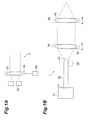
- Fig. 1A and Fig. 1B are schematic configuration diagrams of a collimator device 2 and a laser light source 1 according to the first embodiment.
- the collimator device 2 in Fig. 1A is composed of a laser entrance unit 25 to set a position of emission of a laser beam, a collimating lens 30, a collimating lens setup unit 35 to fix the collimating lens 30, and a position adjustment unit 50 to adjust a position of the laser entrance unit in order to adjust a spacing between a laser exit position (fiber exit end face) 22 of the laser entrance unit 25 and a position of the collimating lens 30.
- the position adjustment unit 50 may be arranged so as to be able to adjust a position of the collimating lens setup unit 35.
- the 1B is constructed including a light source 10, an optical fiber 20, the laser entrance unit 25 to fix the end face 22, the collimating lens 30, the collimating lens setup unit 35 to fix the collimating lens 30, a condensing lens 40, and a condensing lens setup unit 45 to fix the condensing lens 40.
- the laser entrance unit 25, collimating lens 30, and collimating lens setup unit 35 function as a collimator device.
- the light source 10 may include the optical fiber 20 for output.
- the exit end face 22 of the optical fiber 20 may be one having an end cap structure of coreless fiber to reduce the power density of light guided through the optical fiber 20, in order to avoid damage to the end face of the optical fiber 20 at the end.
- the polychromatic light source 10 is, for example, a light source that emits polychromatic light with a spectrum width of 0.9 to 1.3 ⁇ m.
- the polychromatic light emitted from the polychromatic light source 10 is injected into a core region of the optical fiber 20 through one end face 21 of the optical fiber 20.
- the optical fiber 20 is composed of the core region as a central part and a cladding region covering the periphery of the core region, and the polychromatic light injected through the end face 21 into the core region propagates in the core region to be emitted from the other exit end face 22.
- the diameter of the core region in the optical fiber 20 is, for example, about 10 ⁇ m.
- the laser beam with high output power is emitted from the narrow core region, the end face damage will occur at the exit end face 22 of the optical fiber 20.
- the laser beam is emitted through an end cap fiber consisting of a coreless fiber or the like capable of reducing the power density, in order to avoid the end face damage.
- the end cap fiber is a coreless glass rod having the length of 500 ⁇ m and the diameter of 125 ⁇ m.
- the laser light source 1 is designed based on the assumption of the exit diameter and exit angle with these components being set up, so as to accord therewith. In order to simplify the description, the below will describe a configuration without the end cap at the exit end face 22 of the optical fiber 20.
- the polychromatic light emitted from the exit end face 22 of the optical fiber 20 is incident into the collimating lens 30 to be collimated thereby and then the collimated light is output therefrom. Then the collimated polychromatic light is incident into the condensing lens 40 and travels through the condensing lens 40 to be focused at points P (point Pmin (shortest focal position) to point Pmax (longest focal position)) different depending upon wavelengths.
- the exit end face 22 of the optical fiber 20 is fixed by the laser entrance unit 25.
- the collimating lens 30 is fixed by the collimating lens setup unit 35. Relative positions of the collimating lens setup unit 35 and the laser entrance unit 25 can be adjusted in ⁇ m unit by the position adjustment unit 50.
- the condensing lens 40 is fixed by the condensing lens setup unit 45. Relative positions of the condensing lens setup unit 45 and the collimating lens setup unit 35 can be adjusted in 10mm unit.
- collimated light when the light emitted from the polychromatic light source 10 is light of a single wavelength, i.e., monochromatic light, collimated light can be generated from the light emitted from the optical fiber 20 by setting the collimating lens 30 at the position of focal length f corresponding to the wavelength. Then a plane wave can be formed at a desired position by adjusting the position of the collimating lens 30. By setting the condensing lens 40 at the position where the plane wave is formed, a focal spot where the monochromatic light is best focused is formed at the position of the focal length from the condensing lens 40.
- Figs. 2A and 2B show the result of calculation of chromatic aberration in cases where a plane wave is made incident into each of a planoconvex lens and an achromatic lens (model number: 45783-L, available from Edmund Optics).
- Fig. 2A shows focal length differences due to the chromatic aberration of polychromatic light with incidence of a plane wave and Fig.
- FIG. 2B shows the result thereof.
- graph G210 shows the calculation result of the planoconvex lens
- graph G220 the calculation result of the achromatic lens.
- the vertical axis of the graph in Fig. 2B represents the focal position differences of light components of respective wavelengths with respect to 0 set at the position of focus of 0.9 ⁇ m-wavelength-band light after passage through the condensing lens (planoconvex lens or achromatic lens).
- the achromatic lens used in the calculation of Fig. 2B is supposed to be able to demonstrate the function as achromatic lens for polychromatic light of 0.7 ⁇ m to 1.1 ⁇ m.
- the achromatic lens demonstrated the same lens characteristics (change of focal position) for light at the wavelengths of 1.2 ⁇ m and 1.3 ⁇ m as those for the polychromatic light of 0.7 ⁇ m to 1.1 ⁇ m.
- the difference between the focal position for light of the wavelength of 0.9 ⁇ m and the focal position for light of the wavelength of 1.3 ⁇ m was 43 ⁇ m in the case of the achromatic lens, and it was 120 ⁇ m in the case of the planoconvex lens. Namely, it is confirmed that the focal position differences with variation in wavelengths of incident light can be made smaller with the use of the achromatic lens as the condensing lens than with the use of the planoconvex lens.
- the incident light into the condensing lens 40 was generally required to be a plane wave, as shown in Figs. 2A and 2B .
- light components incident into the collimating lens 30 fail to be plane waves at the same position, depending upon wavelengths, and their focal positions become complicated.
- Figs. 3A to 3C schematically show how distance f n ' from the collimating lens 30 to a beam waist (position where a plane wave is formed) varies depending upon the wavelength ⁇ of outgoing light in the case where the light from the polychromatic light source 10 is emitted to diverge from the exit end face 22 of the optical fiber 20 and collimated (into parallel light) by the collimating lens 30.
- the position of the collimating lens 30 (center position) is set at a location L 1 defined so that when light of a wavelength ⁇ 2 is emitted from the collimating lens 30 toward the optical fiber 20, the light of the wavelength ⁇ 2 is focused at the exit end face 22 of the optical fiber 20 ( Fig. 3B ).
- the wavelengths ⁇ 1 , ⁇ 2 , and ⁇ 3 are in the relation of ⁇ 3 ⁇ ⁇ 2 ⁇ ⁇ 1 and at the wavelength ⁇ 1 longer than the wavelength ⁇ 2 , the distance f 1 ' from the collimating lens 30 to the beam waist becomes negative (on the exit end face 22 side of the optical fiber 20) ( Fig. 3A ).
- the beam waist is virtual because there is no beam waist in fact.
- the distance f 3 ' from the collimating lens 30 to the beam waist is positive (on the condensing lens 40 side) ( Fig. 3C ).
- ⁇ f' is defined as a position variation with respect to f 2 ', of the distance f n ' to the beam waist at each of the wavelength ⁇ 1 and the wavelength ⁇ 3 .
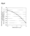
- Fig. 4 shows the position variation ⁇ f' of beam waist at the wavelengths of 0.9 to 1.3 ⁇ m where the reference wavelength ⁇ 2 is 1.1 ⁇ m. ⁇ f' varies between about +200 mm and about -400 mm.
- the median of focal spot positions at the wavelengths of 0.9 to 1.3 ⁇ m (the median of the variation range of focal length differences at the wavelengths of 0.9 to 1.3 ⁇ m) is near the wavelength of 1.1 ⁇ m in Figs. 2A and 2B , whereas Fig. 4 gives the impression that it is considerably far from the wavelength of 1.1 ⁇ m.
- the collimating lens 30 used was the same as the achromatic lens used and shown in Figs. 2A and 2B .
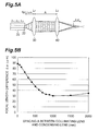
- Fig. 5A is a drawing in which the condensing lens 40 in Fig. 2A (which is the same as the achromatic lens shown in Figs. 2A and 2B ) is arranged in the configuration of the collimator device in Figs. 3A to 3C , where the reference wavelength ⁇ 2 is 1.1 ⁇ m.
- Fig. 4 shows only the case where the distance between the exit end face 22 of optical fiber 20 and the collimating lens 30 is set at f 1.1 ⁇ m (focal length of the collimating lens 30 for light with the reference wavelength of 1.1 ⁇ m)
- Figs. 6A and 6B show the result of this calculation.
- Fig. 6A shows a configuration wherein, with respect to Fig. 5A , the setup position L 1 of the collimating lens 30 is the position represented by f 1.1 ⁇ m (reference position) and is changed by ⁇ (adjustment position) from the reference position.
- the position variation ⁇ f' of beam waist herein refers to "f n '( ⁇ ) - f 1.1 ⁇ m '( ⁇ )," where f n '( ⁇ ) represents the focal position of the collimating lens 30 at the wavelength ⁇ n in a setup in which the setup position of the collimating lens is "f 1.1 ⁇ m ⁇ .”
- graph G621 for the case of
- ⁇ f once has a minimum (local minimum point P0) at +50 ⁇ m; it again has a peak (sub-peak P2 being a local maximum point of a second largest value though being smaller than the main peak P1) near +100 ⁇ m; then ⁇ f decreases toward 0 with further movement of the position of the collimating lens in the positive direction.
- ⁇ f must have the maximum point, but the existence of the minimum point thereof was beyond expectation.
- Fig. 7 showed the unexpected behavior of beam waist variation range ⁇ f
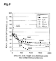
- Fig. 8 shows the calculation result of variation of wavelength-dependent focal length difference ⁇ against spacing A between the collimating lens 30 and the condensing lens 40, with variation in the adjustment position ⁇ under the same condition as in Figs. 6A and 6B .
- the collimating lens 30 and the condensing lens 40 used were the same as the achromatic lens shown in Figs. 2A and 2B .
- Fig. 8 shows the calculation result of variation of wavelength-dependent focal length difference ⁇ against spacing A between the collimating lens 30 and the condensing lens 40, with variation in the adjustment position ⁇ under the same condition as in Figs. 6A and 6B .
- the collimating lens 30 and the condensing lens 40 used were the same as the achromatic lens shown in Figs. 2A and 2B .
- Fig. 8 shows the calculation result of variation of wavelength-dependent focal length difference ⁇ against spacing A between the collim
- ⁇ +50 ⁇ m
- ⁇ 6 ⁇ m
- This value was approximately one seventh when compared to ⁇ (43 ⁇ m) of the achromatic lens shown in Figs. 2A and 2B .
- Figs. 7 and 8 above were not checked with other achromatic lenses, but we consider that the relation as shown in Fig. 8 must be obtained when a minimum of ⁇ f is observed in investigation of variation of ⁇ f, with variation in relation between the position of outgoing light from the optical fiber 20 and the setup position of the collimating lens 30.
- Fig. 9 is a schematic configuration diagram of a laser light source 100 according to the second embodiment.
- This laser light source 100 according to the second embodiment includes the configuration of the laser light source 1 according to the first embodiment shown in Fig. 1B , and is further provided with a pinhole mask 26 installed at the exit position of the laser beam or at the exit end face 22 of the optical fiber 20 in which single-mode light propagates.
- a pinhole 260 is formed in the pinhole mask 26 and the size (aperture diameter) of the pinhole 260 is approximately equal to or 10% smaller than the mode field diameter of the optical fiber 20 for the shortest wavelength component out of wavelength components of the polychromatic light emitted from the polychromatic light source 10.
- the pinhole mask 26 is preferably one having the thickness as small as possible, about 100 ⁇ m or less.
- the sectional shape of the pinhole 260 is preferably such a taper shape as not to block the shortest-wavelength light component propagating in the pinhole 260 and diverging because of diffraction.
- the pinhole is set up so that the respective beam diameters at the exit end face 22 of the optical fiber 20, of all the wavelength components having passed through the pinhole 260 are approximately equal.
- the mode field diameters for wavelength components on the long wavelength side become larger than that for the shortest wavelength component.
- the present invention is the invention under the condition that the mode field diameters for the respective wavelengths are equal, and it is considered without the pinhole that there are mode field diameters depending upon wavelengths and there appear focal length differences ⁇ reflecting the mode field diameters.
Landscapes
- Physics & Mathematics (AREA)
- Optics & Photonics (AREA)
- Engineering & Computer Science (AREA)
- Plasma & Fusion (AREA)
- Mechanical Engineering (AREA)
- General Physics & Mathematics (AREA)
- Optical Couplings Of Light Guides (AREA)
- Semiconductor Lasers (AREA)
Applications Claiming Priority (3)
| Application Number | Priority Date | Filing Date | Title |
|---|---|---|---|
| JP2011189126 | 2011-08-31 | ||
| US201261616109P | 2012-03-27 | 2012-03-27 | |
| PCT/JP2012/070513 WO2013031524A1 (ja) | 2011-08-31 | 2012-08-10 | コリメータ装置及びレーザ光源 |
Publications (2)
| Publication Number | Publication Date |
|---|---|
| EP2752702A1 true EP2752702A1 (de) | 2014-07-09 |
| EP2752702A4 EP2752702A4 (de) | 2016-01-06 |
Family
ID=47743377
Family Applications (1)
| Application Number | Title | Priority Date | Filing Date |
|---|---|---|---|
| EP12827409.9A Withdrawn EP2752702A4 (de) | 2011-08-31 | 2012-08-10 | Kollimator und laserlichtquelle |
Country Status (5)
| Country | Link |
|---|---|
| US (1) | US8854737B2 (de) |
| EP (1) | EP2752702A4 (de) |
| JP (1) | JP5983613B2 (de) |
| CN (1) | CN103765296B (de) |
| WO (1) | WO2013031524A1 (de) |
Families Citing this family (21)
| Publication number | Priority date | Publication date | Assignee | Title |
|---|---|---|---|---|
| DE112013004303T5 (de) * | 2012-08-30 | 2015-05-13 | Sumitomo Electric Industries, Ltd. | Laserlichtquelle |
| JP2014079802A (ja) * | 2012-10-18 | 2014-05-08 | Sumitomo Electric Ind Ltd | レーザ加工方法およびレーザ光照射装置 |
| DE102014224182A1 (de) * | 2014-11-26 | 2016-06-02 | Robert Bosch Gmbh | Vorrichtung und Verfahren zur Lasermaterialbearbeitung |
| US12152858B2 (en) | 2014-12-23 | 2024-11-26 | Jm Acquisitions Inc | Aiming device for a firearm |
| US20160231084A1 (en) * | 2014-12-23 | 2016-08-11 | Jm Acquisitions, Inc. | Triple wavelength pointing device |
| WO2016151740A1 (ja) * | 2015-03-23 | 2016-09-29 | 技術研究組合次世代3D積層造形技術総合開発機構 | レーザ加熱制御機構、レーザ加熱制御方法、レーザ加熱制御プログラムおよび3次元造形装置 |
| US10422998B1 (en) | 2015-06-03 | 2019-09-24 | Mark Belloni | Laser transformer lens |
| US9968416B2 (en) * | 2015-12-16 | 2018-05-15 | Novartis Ag | Ophthalmic illumination systems, devices, and methods |
| JP6895621B2 (ja) * | 2016-08-31 | 2021-06-30 | パナソニックIpマネジメント株式会社 | レーザ加工ヘッドおよびレーザ加工装置 |
| CN108508617A (zh) * | 2017-02-24 | 2018-09-07 | 中国科学院半导体研究所 | 激光器准直装置及准直方法 |
| JP7094683B2 (ja) * | 2017-10-06 | 2022-07-04 | 住友電気工業株式会社 | 光受信モジュール |
| WO2020190489A1 (en) | 2019-03-21 | 2020-09-24 | Corning Incorporated | Systems for and methods of forming micro-holes in glass-based objects using an annular vortex laser beam |
| KR20220025060A (ko) | 2019-07-01 | 2022-03-03 | 코닝 인코포레이티드 | 곡선형 준-비-회절 레이저 빔을 사용하여 투명 가공물을 레이저 가공하는 방법 |
| US11892652B1 (en) | 2020-04-07 | 2024-02-06 | Mark Belloni | Lenses for 2D planar and curved 3D laser sheets |
| CN111352194A (zh) * | 2020-04-26 | 2020-06-30 | 时代科技(深圳)有限公司 | 一种平面光源及光学装置 |
| JP2022033590A (ja) * | 2020-08-17 | 2022-03-02 | シャープ福山レーザー株式会社 | 出射光調整装置及び出射光調整方法 |
| US12434331B2 (en) * | 2020-09-11 | 2025-10-07 | Corning Incorporated | Laser forming non-square edges in transparent workpieces using modified airy beams |
| US12006245B2 (en) * | 2020-09-11 | 2024-06-11 | Corning Incorporated | Laser forming non-square edges in transparent workpieces using low intensity airy beams |
| CN114253003B (zh) * | 2021-12-06 | 2023-09-29 | 北京遥测技术研究所 | 一种管壳激光准直调试装置及方法 |
| CN114976844B (zh) * | 2022-07-25 | 2022-10-25 | 中国人民解放军国防科技大学 | 光纤激光放大器收发一体化系统 |
| CN115598024B (zh) * | 2022-11-16 | 2023-03-14 | 长春光吉科技有限责任公司 | 细胞分级计数装置及其方法 |
Family Cites Families (11)
| Publication number | Priority date | Publication date | Assignee | Title |
|---|---|---|---|---|
| JPH01235910A (ja) * | 1988-03-16 | 1989-09-20 | Canon Inc | 光源ユニツト |
| US6356342B1 (en) * | 1996-05-07 | 2002-03-12 | Purup-Eskofot A/S | Method and apparatus for illumination of light-sensitive materials |
| US6075650A (en) * | 1998-04-06 | 2000-06-13 | Rochester Photonics Corporation | Beam shaping optics for diverging illumination, such as produced by laser diodes |
| CN1287366C (zh) * | 2002-11-29 | 2006-11-29 | 富士通株式会社 | 准直光学系统和光学信息存储设备 |
| US6768593B1 (en) * | 2003-06-24 | 2004-07-27 | Suganda Jutamulia | Fiber-coupled laser diode having high coupling-efficiency and low feedback-noise |
| JP2005327395A (ja) * | 2004-05-14 | 2005-11-24 | Sony Corp | 光ピックアップ及びこれを用いた記録及び/又は再生装置 |
| JP4833558B2 (ja) * | 2005-02-07 | 2011-12-07 | パナソニック株式会社 | レーザトーチ |
| US20090161488A1 (en) * | 2007-12-19 | 2009-06-25 | Ralf Ferber | Method to Estimate Ray Parameter for Seismograms |
| DE102007061737A1 (de) * | 2007-12-20 | 2009-06-25 | Robert Bosch Gmbh | Verfahren zur Montage und Justage einer elektro-optischen Vorrichtung sowie Messgerät montiert und justiert nach einem derartigen Verfahren |
| CN201654338U (zh) * | 2009-11-17 | 2010-11-24 | 上海微电子装备有限公司 | 一种双频激光干涉仪的光纤准直器 |
| CN201725077U (zh) * | 2010-06-18 | 2011-01-26 | 深圳市大族激光科技股份有限公司 | 准直镜调光系统 |
-
2012
- 2012-08-10 CN CN201280042555.1A patent/CN103765296B/zh not_active Expired - Fee Related
- 2012-08-10 WO PCT/JP2012/070513 patent/WO2013031524A1/ja not_active Ceased
- 2012-08-10 JP JP2013531200A patent/JP5983613B2/ja not_active Expired - Fee Related
- 2012-08-10 EP EP12827409.9A patent/EP2752702A4/de not_active Withdrawn
- 2012-08-31 US US13/601,329 patent/US8854737B2/en not_active Expired - Fee Related
Also Published As
| Publication number | Publication date |
|---|---|
| EP2752702A4 (de) | 2016-01-06 |
| US8854737B2 (en) | 2014-10-07 |
| CN103765296A (zh) | 2014-04-30 |
| CN103765296B (zh) | 2016-05-25 |
| JPWO2013031524A1 (ja) | 2015-03-23 |
| WO2013031524A1 (ja) | 2013-03-07 |
| US20130050838A1 (en) | 2013-02-28 |
| JP5983613B2 (ja) | 2016-09-06 |
Similar Documents
| Publication | Publication Date | Title |
|---|---|---|
| US8854737B2 (en) | Collimator device and laser light source | |
| US9395550B2 (en) | Laser light source | |
| US7948680B2 (en) | Spectral beam combination using broad bandwidth lasers | |
| WO2014061438A1 (ja) | レーザ加工方法およびレーザ光照射装置 | |
| US8903209B2 (en) | Spectral beam combining and wavelength multiplexing with an optical redirecting element | |
| JP2004037840A (ja) | 分散補償器及び分散補償システム | |
| JP6444674B2 (ja) | レーザ作動光源 | |
| US10025108B2 (en) | Device for homogenizing laser radiation | |
| US20190018253A1 (en) | Optical Arrangement and Method for Producing a Combined Beam of a Plurality of Laser Light Sources | |
| US20210394304A1 (en) | Fiber coupled laser with variable beam parameters product | |
| US11876338B2 (en) | Device for combining at least two laser beams | |
| US20130135710A1 (en) | Wavelength conversion device and laser device | |
| EP3423878B1 (de) | Gemeinsame ausrichtung von lateral beabstandeten strahlen | |
| EP3214470A1 (de) | Gemeinsame ausrichtung von lateral beabstandeten strahlen | |
| GB2547923A (en) | Co-aligning laterally displaced radiation beams | |
| JP2004173054A (ja) | 分散補償器及び分散補償システム | |
| Baumhacker et al. | Adaptive optics in a multistage TiS laser |
Legal Events
| Date | Code | Title | Description |
|---|---|---|---|
| PUAI | Public reference made under article 153(3) epc to a published international application that has entered the european phase |
Free format text: ORIGINAL CODE: 0009012 |
|
| 17P | Request for examination filed |
Effective date: 20140324 |
|
| AK | Designated contracting states |
Kind code of ref document: A1 Designated state(s): AL AT BE BG CH CY CZ DE DK EE ES FI FR GB GR HR HU IE IS IT LI LT LU LV MC MK MT NL NO PL PT RO RS SE SI SK SM TR |
|
| DAX | Request for extension of the european patent (deleted) | ||
| RA4 | Supplementary search report drawn up and despatched (corrected) |
Effective date: 20151209 |
|
| RIC1 | Information provided on ipc code assigned before grant |
Ipc: G02B 13/00 20060101ALI20151203BHEP Ipc: B23K 26/04 20060101ALI20151203BHEP Ipc: G02B 27/30 20060101AFI20151203BHEP Ipc: B23K 26/06 20060101ALI20151203BHEP Ipc: B23K 26/08 20060101ALI20151203BHEP |
|
| STAA | Information on the status of an ep patent application or granted ep patent |
Free format text: STATUS: THE APPLICATION HAS BEEN WITHDRAWN |
|
| 18W | Application withdrawn |
Effective date: 20170515 |