EP2754826A2 - Unité d'entraînement pour une porte à tambour plate en forme de disque - Google Patents
Unité d'entraînement pour une porte à tambour plate en forme de disque Download PDFInfo
- Publication number
- EP2754826A2 EP2754826A2 EP14000034.0A EP14000034A EP2754826A2 EP 2754826 A2 EP2754826 A2 EP 2754826A2 EP 14000034 A EP14000034 A EP 14000034A EP 2754826 A2 EP2754826 A2 EP 2754826A2
- Authority
- EP
- European Patent Office
- Prior art keywords
- drive unit
- rotor part
- stator
- turnstile
- revolving door
- Prior art date
- Legal status (The legal status is an assumption and is not a legal conclusion. Google has not performed a legal analysis and makes no representation as to the accuracy of the status listed.)
- Granted
Links
Images


Classifications
-
- H—ELECTRICITY
- H02—GENERATION; CONVERSION OR DISTRIBUTION OF ELECTRIC POWER
- H02K—DYNAMO-ELECTRIC MACHINES
- H02K1/00—Details of the magnetic circuit
- H02K1/06—Details of the magnetic circuit characterised by the shape, form or construction
- H02K1/22—Rotating parts of the magnetic circuit
- H02K1/27—Rotor cores with permanent magnets
- H02K1/2786—Outer rotors
- H02K1/2787—Outer rotors the magnetisation axis of the magnets being perpendicular to the rotor axis
- H02K1/2789—Outer rotors the magnetisation axis of the magnets being perpendicular to the rotor axis the rotor consisting of two or more circumferentially positioned magnets
- H02K1/2791—Surface mounted magnets; Inset magnets
-
- E—FIXED CONSTRUCTIONS
- E05—LOCKS; KEYS; WINDOW OR DOOR FITTINGS; SAFES
- E05F—DEVICES FOR MOVING WINGS INTO OPEN OR CLOSED POSITION; CHECKS FOR WINGS; WING FITTINGS NOT OTHERWISE PROVIDED FOR, CONCERNED WITH THE FUNCTIONING OF THE WING
- E05F15/00—Power-operated mechanisms for wings
- E05F15/60—Power-operated mechanisms for wings using electrical actuators
- E05F15/603—Power-operated mechanisms for wings using electrical actuators using rotary electromotors
- E05F15/608—Power-operated mechanisms for wings using electrical actuators using rotary electromotors for revolving wings
-
- H—ELECTRICITY
- H02—GENERATION; CONVERSION OR DISTRIBUTION OF ELECTRIC POWER
- H02K—DYNAMO-ELECTRIC MACHINES
- H02K11/00—Structural association of dynamo-electric machines with electric components or with devices for shielding, monitoring or protection
- H02K11/30—Structural association with control circuits or drive circuits
-
- E—FIXED CONSTRUCTIONS
- E05—LOCKS; KEYS; WINDOW OR DOOR FITTINGS; SAFES
- E05D—HINGES OR SUSPENSION DEVICES FOR DOORS, WINDOWS OR WINGS
- E05D15/00—Suspension arrangements for wings
- E05D15/02—Suspension arrangements for wings for revolving wings
-
- E—FIXED CONSTRUCTIONS
- E05—LOCKS; KEYS; WINDOW OR DOOR FITTINGS; SAFES
- E05Y—INDEXING SCHEME ASSOCIATED WITH SUBCLASSES E05D AND E05F, RELATING TO CONSTRUCTION ELEMENTS, ELECTRIC CONTROL, POWER SUPPLY, POWER SIGNAL OR TRANSMISSION, USER INTERFACES, MOUNTING OR COUPLING, DETAILS, ACCESSORIES, AUXILIARY OPERATIONS NOT OTHERWISE PROVIDED FOR, APPLICATION THEREOF
- E05Y2800/00—Details, accessories and auxiliary operations not otherwise provided for
- E05Y2800/10—Additional functions
- E05Y2800/106—Lighting
-
- E—FIXED CONSTRUCTIONS
- E05—LOCKS; KEYS; WINDOW OR DOOR FITTINGS; SAFES
- E05Y—INDEXING SCHEME ASSOCIATED WITH SUBCLASSES E05D AND E05F, RELATING TO CONSTRUCTION ELEMENTS, ELECTRIC CONTROL, POWER SUPPLY, POWER SIGNAL OR TRANSMISSION, USER INTERFACES, MOUNTING OR COUPLING, DETAILS, ACCESSORIES, AUXILIARY OPERATIONS NOT OTHERWISE PROVIDED FOR, APPLICATION THEREOF
- E05Y2900/00—Application of doors, windows, wings or fittings thereof
- E05Y2900/10—Application of doors, windows, wings or fittings thereof for buildings or parts thereof
- E05Y2900/13—Type of wing
- E05Y2900/132—Doors
Definitions
- the present invention relates to a drive unit for a revolving door with an electronically commutated Dahlpolmotor, wherein the Dahlpolmotor has a number of coil elements and magnetic elements and has a flat basic structure. Furthermore, the invention is directed to the arrangement of such a drive unit on a revolving door and to a method for arranging the drive unit.
- the DE 10 2010 024 108 A1 shows a generic drive unit for a revolving door with an electronically commutated Dahlpolmotor, and the Dahlpolmotor is flat and has a round basic structure.
- the Dahlpolmotor has an axis of rotation, which coincides with the axis of rotation of the turnstile of the revolving door.
- a drive unit for a revolving door as electronically commutated Dahlpolmotor allows a particularly advantageous integration of the drive unit in the structure of the revolving door.
- the drive unit can be mounted on the bottom side, and it is not a large receiving space for receiving the drive unit in the shell of a building necessary.
- the flat design of the drive unit results in particular from the fact that the electronically commutated Dahlpolmotor can be connected directly to the turnstile of the revolving door, so that the drive unit does not have to have a transmission.
- Electronically commutated multi-pole motors however, have output shafts to which components to be driven, for example the turnstile of a revolving door, are arranged be transmitted to the rotational movement of the output shaft to the components.
- Newer revolving doors require drive units that must be very flat.
- the use of a transmission in conjunction with an output shaft already causes a significant increase in the height of the drive unit in the rotational axis of the turnstile, and especially in floor-mounted drive units, but also in ceiling-mounted drive units large heights often lead to constructive, but also to aesthetic disadvantages in the device the revolving door, for example, in the facade of a building.
- the object of the invention is to provide a drive unit for a revolving door, an arrangement of a drive unit in a revolving door and a revolving door with such a drive unit, which has a low overall height and is simple.
- the invention proposes a drive unit for a revolving door with an electronically commutated Dahlpolmotor with a number of coil elements and with a number of magnetic elements, wherein the Dahlpolmotor has a flat-shaped basic structure and comprises a disc-shaped or cup-shaped stator part, which can be arranged on a static structural component, and further comprising a disc-shaped or pot-shaped rotor part, which is arranged plane-parallel to the stator and which is drivingly connected to a turnstile of the revolving door, wherein the coil elements and the magnetic elements are received in the region between the stator and the rotor part.
- the invention is based on the idea to connect the electronically commutated Drivepolmotor gearless with the turnstile of the revolving door and to easily arrange the stator on a stationary structural component in particular the revolving door, but for example, on the facade in which the revolving door is introduced ,
- the rotor part can be brought in direct connection with the turnstile of the revolving door in a likewise simple manner and thus store the turnstile.
- the electronically commutated Drivepolmotor according to the invention is carried out essentially of two disc-shaped or cup-shaped parts, and the coil elements and the magnetic elements are between the disc-shaped or cup-shaped parts arranged.
- the stator and the rotor part together form at the same time the housing of Dahlpolmotors.
- the electronically commutated Dahlpolmotor can be made particularly flat, the disc-shaped or pot-shaped parts of the stator and the rotor part does not necessarily have to have the same diameter, and the parts can project beyond each other radially.
- the disc-shaped basic structure of the Dahlpolmotors creates a kind of turntable, which can be arranged in an advantageous manner between the structural component and the turnstile of the revolving door.
- the structural component can be present both on the ceiling side and on the floor side of the turnstile, so that the Dahlpolmotor can be arranged both on the ceiling side and on the bottom side in or on the revolving door.
- the ratio of height to diameter of the substantially round, flat-shaped basic structure of the electronically commutated Dahlpolmotors a value of at least 1: 3, preferably of at least 1: 4, more preferably of at least 1: 5, and most preferably of 1: 8 and more.
- the ratio of height to diameter results from the parallel distance of the disc-shaped or pot-shaped stator part to the disk-shaped or cup-shaped rotor part of the Dahlpolmotors to the diameter of the stator and / or the rotor part.
- the ratios of height to diameter of up to 1: 8 and more can only be achieved, and it has been shown that even basic structures of poly pole motors are the driving force for Revolving doors can be used, which can reach a ratio of height to diameter of more than 1:12.
- a disk-shaped shape is a flat cylinder in which the diameter is several times greater than the height.
- the Dahlpolmotor have a diameter of about 500 mm and a height of about 40 mm.
- the feature of a disc-shaped shape is also given when a Dahlpolmotor primary disk-shaped shape is deliberately redesigned to another similar shape.
- a flat, polygonal stump enclose the per se round stator or rotor part or for example, the stator or the rotor part has a deviating from a plate shape, non-circular shape, for example, a flat Cube.
- Such a transformation can be carried out by enclosing the rotor part or the stator part with a correspondingly shaped housing or by a corresponding transformation of the coil cores.
- a control unit of the multi-pole motor can likewise be accommodated between the stator part and the rotor part.
- the control unit can be designed both for power supply, commutation and control for the basic operation of Dahlpolmotors, but also for signal processing for the control of Dahlpolmotors, for example for a start / stop function, an emergency stop or rotation monitoring of the rotation of the turnstile of the revolving door.
- the integration of the control unit of the Dahlpolmotor in the space between the stator and the rotor part creates a ready to connect, modular drive unit, which only has to be connected to a power supply and signal connections for example, an interface module for external control of the drive unit.
- the rotor part is received rotatably mounted on the stator part about a particular imaginary drive axle.
- at least one bearing in particular at least one thrust bearing and / or at least one radial bearing, can be arranged between the stator part and the rotor part.
- the stator is located here in a rigid arrangement on the structural component, which may be part of the revolving door of a part of the revolving door, for example, the frame of the revolving door, but also part of the entire facade of a building.
- At this stationary stator part of the rotor part can be rotatably received via a bearing assembly, and with the rotor part of the turnstile of the revolving door is connected.
- the particular advantage can be achieved that forces can be transmitted from the structural component to the turnstile, and for example, the structural component part of the upper-side frame structure of the revolving door, which is supported via the thrust bearing on the turnstile, without the rotational mobility of the hub through the load, the is supported by the Dahlpolmotor is impaired. Consequently, in particular, the thrust bearing can be made oversized, and the frame structure of the revolving door can be designed so that a power transmission through the turnstile and the Dahlpolmotor in the direction of the axis of rotation of the hub, which coincides with the drive axis of the Dahlpolmotors, can be considered.
- the turnstile can have two, three, four or more rotary blades and does not necessarily have the basic shape of a cross.
- the coil elements can be arranged radially inwardly relative to the magnetic elements.
- the coil elements may comprise winding bodies which are arranged on the stator part in such a way that they are aligned essentially radially between the stator part and the rotor part. If the magnetic elements are arranged radially on the outside relative to the coil elements, then an advantageous, in particular high-torque configuration of the poly pole motor is created, which thereby forms a so-called external rotor. This is due in particular to the fact that the magnetic gap between the magnetic elements and the coil elements has an increased distance from the drive axis of the drive unit. Characterized in that the magnetic elements have smaller dimensions than the coil elements, the air gap between the coil elements and the magnetic elements with respect to the drive axis can be placed outside by the magnetic elements be arranged outside relative to the coil elements, so that the air gap radius is increased.
- the coil elements can be arranged resting on the stator part, and the rotor part can have a pot shape with a pot shell section which covers the disk-shaped stator part substantially laterally or surrounds it.
- the magnetic elements can be arranged on the inside in Topfmantelabsacrificing, wherein the coil elements are arranged on the stator. If rotor part and stator part are mounted parallel to one another at a distance from one another, then the coil elements and the magnetic elements can face each other in the radial direction.
- the stator part can be arranged resting on the structural component, and the rotor part can be designed to connect the turnstile and in particular the rotary vanes, wherein the rotary vanes are preferably directly connected to the outer outer surface of the rotor part.
- the rotor part when the rotor part is disc-shaped or pot-shaped, this has a flat, in particular planar bottom part, which has an outer surface facing in the direction of the rotary wing of the turnstile.
- the rotor part can be connected to the turnstile in a particularly simple manner.
- the rotary blades can be individually connected to the rotor part, in particular screwed.
- the Dahlpolmotor may comprise an output shaft which is rotationally connected to the rotor part and which extends in the drive axis in which rotates the turnstile.
- the turnstile can be connected to the output shaft, for which in particular an adapter element can be used.
- the adapter element may for example form an adapter cross, and the adapter cross forms receiving arms to which individual rotary blades can be attached.
- the Dahlpolmotor may comprise at least one rotary feedthrough, by means of at least one electrical line electrical means in Dahlpolmotor, in particular the control unit, with an element rotating with the rotor member, in particular with the turnstile, is electrically connectable.
- the rotary feedthrough can be arranged integrated with particular advantage in Dahlpolmotor.
- the recorded in Dahlpolmotors control unit is preferably arranged resting on the stator, and to provide an electrical connection between the rotating hub and the stationary control unit, the rotary feedthrough may be provided, which can be arranged in particular between the rotor part and the stator.
- the multi-pole motor has an output shaft
- it can be designed as a hollow shaft, and the rotary feedthrough can be accommodated on the inside in the hollow output shaft or at least the electric line can run through the hollow shaft.
- the electrical lines can be guided in particular through the hollow shaft in the turnstile, and in the turnstile sensors, electrical switches, emergency or the like may be attached, which is located on the located between the stator and the rotor part rotary union with the electrical control unit during the rotational movement of the Turnstile are electrically connected.
- the electronically commutated Drivepolmotor can be integrated into the bottom side of the revolving door, so that the Dahlpolmotor together extends at least in sections on the height of a scaffold built on a shell, with particular advantage of the electronically commutated Drivepolmotor can be arranged visible on the underside of a structural component that located above the turnstile of the revolving door. The visibility is given especially for persons located in the turnstile.
- the visible part of the Dahlpolmotors is formed in particular by the disc-shaped or cup-shaped rotor part, which may have a particular decorative surface or an additional aperture element with particular advantage.
- the visible arrangement of the Dahlpolmotors can be achieved that, for example, lighting means can be integrated in the engine, for example, the disc-shaped or cup-shaped rotor part may be at least partially formed of a light transparent material, and between the stator and the rotor part bulbs can be arranged , It is also conceivable to enclose the disc-shaped Dahlpolmotor with a luminous edge, with particular advantage all bulbs can be formed by semiconductor bulbs.
- the Dahlpolmotor can still have a position or angle encoder, this is used for commutation and determination of angular positions and the rotational speed of the turnstile.
- the present invention is further directed to an arrangement of a drive unit for a revolving door with an electronically commutated Drivepolmotor with a number of coil elements and with a number of magnetic elements, wherein the Dahlpolmotor has a flat-shaped basic structure and a disc-shaped or cup-shaped Stator part which can be arranged on a stationary structural component, and further comprising a disc-shaped or cup-shaped rotor part, which is arranged plane-parallel to the stator and drivingly connected to a turnstile of the revolving door, wherein the coil elements and the magnetic elements in the region between the stator and the Rotor part are included.
- a receiving pot For arranging the drive unit, a receiving pot may be provided, with which the drive unit is at least partially embedded in the structural component, in which case the multipolar motor is accommodated in the receiving pot.
- the receptacle may include a bottom portion, a skirt portion, and more particularly a collar portion, and the collar portion may extend in a plane parallel to the bottom portion.
- the bottom area does not necessarily have to be closed, and the receiving pot can also comprise an open bottom, so that, as a modification to a receiving pot, a receiving ring for receiving the drive unit can be formed.
- the drive unit can be integrated on the ceiling side in the revolving door, wherein at least one underside element can be arranged on the underside of the structural component, which is held at least partially by the receiving pot and can serve as a decorative element, in particular if the drive unit is not completely connected to the receiving pot in the Structural component is embedded, a vertical area between the collar of the pot and the bottom of the structural component can be formed in which the decorative element is arranged, in particular mounted or inserted.
- the drive unit can be mounted directly under the structural component, wherein the drive unit can also be partially embedded in the structural component, so that the drive unit with a part of its height in the structural component extends into it.
- the receiving pot can also be designed such that the drive unit is embedded with its entire height in the structural component.
- the pot can be used to particular advantage to arrange the drive unit subsequently in an existing revolving door, and to use for driving the turnstile.
- a conventional, a motor and a transmission comprehensive drive unit can be dismantled, and between the structural component, such as the ceiling element of the revolving door, and the turnstile, the drive unit can be retrofitted into the revolving door by means of the pot.
- the invention is directed to a revolving door with a drive unit with an electronically commutated Dahlpolmotor with a number of coil elements and a number of magnetic elements
- the Dahlpolmotor has a flat-shaped basic structure and comprises a disc-shaped or cup-shaped stator part, which is arranged on a stationary structural component is, and further comprising a disc-shaped or cup-shaped rotor part which is arranged plane-parallel to the stator and which is drivingly connected to a turnstile of the revolving door, wherein the coil elements and the magnetic elements are received in the region between the stator and the rotor part.
- the invention is directed to a method for arranging a drive unit, wherein the method comprises at least the steps of providing the drive unit, providing a holding pot for receiving the drive unit, arranging the drive unit to the receiving pot before or after arranging the receiving pot on or in a structural component.
- the step of tying a turnstile and, in particular, rotary blades to a rotor part of the multi-pole motor can be provided.
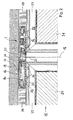
- FIG. 1 an embodiment of a drive unit in the form of a Dahlpolmotors 1 is shown in a cross-sectional view.
- the drive unit can be used to drive a turnstile of a revolving door application.
- the drive unit is arranged, for example, on the underside of a structural component 13 and forms an electronically commutated multi-pole motor 1 with a number of coil elements 10, which correspond to a number of magnetic elements 11.
- the coil elements 10 and the magnetic elements 11 are arranged between a stator part 12 and a rotor part 14.
- the stator 12 is exemplified disk-shaped and has individual protruding areas.
- the outer circumference of the Topfmantelabiteses 20 corresponds to the final, circumferential edge of the approximately disc-shaped stator 12. Due to the fact that the rotor part 14 is pot-shaped by the Topfmantelab bainites 20, formed between the stator 12 and the rotor part 14, an installation space in which the coil elements 10 and the magnetic elements 11 are arranged.
- the coil elements 10 are arranged on a structure section 31 of the stator part 12, and the structure section 31 is designed as a section running around the drive axis 17 and thus forms the circular path, on which a plurality of coil elements 10 are distributed over the circumference are, by the cross-sectional view only two coil elements 10 are shown by way of example.
- the magnetic elements 11 are accommodated on the inside in the pot casing section 20, and distributed over the circumference of the rotor part 14 is a plurality of magnetic elements 11, which corresponds to the plurality of coil elements 10.
- the electronic commutation of the coil elements 10 can be generated by using different Bestromungsalgorithmen the coil elements 10 on the circular path circulating magnetic fields which can migrate from coil element to coil element, whereby a drive torque between the coil elements 10 and the magnetic elements 11 is generated. Due to the arrangement of the coil elements 10 on the stator part 12 and the magnetic elements 11 on the rotor part 14, a torque between the stator 12 and the rotor part 14 is generated by the electronic commutation of the coil elements 10.
- a thrust bearing 18 and a radial bearing 19 is provided, the bearings 18 and 19 receive an insert member 32 rotatably mounted on the stator 12, and the insert member 32 is rotationally connected via screw 33 with the cup-shaped rotor member 14.
- the electronically commutated Drivepolmotor 1 has a flat, round basic structure and has an example of a ratio of height to diameter of about 1:10.
- the drive unit according to the invention is particularly advantageous for driving the turnstile of a revolving door, and the drive unit can between the turnstile and a top-side structural component 13 or between the turnstile and a bottom structural member, without requiring substantial space, as in the following FIG. 2 shown in more detail.
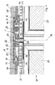
- FIG. 2 shows an arrangement of a drive unit to a structural component 13, wherein a turnstile 15 a revolving door 15 with a plurality of rotary blades 21 is arranged on the cup-shaped rotor part 14 in the drive unit.
- the rotor part 14 has an outer surface 22 pointing in the direction of the turnstile 15, and the rotary vanes 21 are each rigidly connected to the rotor part 14 via screw elements 34, wherein an aperture element 30 is arranged between the rotor part 14 and the rotary vanes 21.
- the stator part 12 of the electronically commutated Drivepolmotors 1 is connected in a manner not shown in detail with the structural component 13 at this holding, wherein the Dahlpolmotor 1 is arranged on the underside of the structural component 13.
- the low overall height of the drive unit can be bridged by brush elements 35, which are arranged outside the Drivepolmotors 1 between the rotary blades 21 and the structural component 13.
- the brush elements 35 can be fastened to the rotary blades 21 and grind on the structural component 13.
- the rotary vanes 21 have frame profiles 39, by means of which the rotary vanes 21 are attached by means of screw elements 34 to the rotor part 14, and between the rotary vanes 21 and the rotor part 14 is shown an aperture element 30 which can serve as a decorative trim.
- the exemplary embodiment also shows a control unit 16, which is arranged in the installation space between the stator part 12 and the rotor part 14. Also shown is an electrical line 26, which is guided via a rotary feedthrough 25 from the turnstile 15 to the control unit 16.
- the Rotary feedthrough 25 permits electrical contacting of a section of the electrical line 26 rotating with the turnstile 15 with a section of the electrical line 26 resting in the stator section 12.
- the control unit 16 can be connected to sensor elements via the electrical line 26 and received in the turnstile 15 are and therefore rotate about the drive shaft 17 with the turnstile 15.
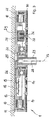
- FIG. 3 shows a further embodiment of the drive unit in a lower-side arrangement on a structural component 13.
- the drive unit has a stator part 12 in a substantially disc-shaped design, and a rotor part 14, which has a cup-shaped design.
- a number of coil elements 10 are arranged on the stator part 12, and a number of magnetic elements 11 are arranged on the rotor part 14, wherein the magnetic elements 11 are located on the outside of the coil elements 10.
- On the rotor part 14, a further diaphragm element 30 is arranged.
- a control unit 16 which is connected to an electrical line 26, and the electrical line 26 is divided by a rotary feedthrough 25 in a stationary part and in a co-rotating about a drive axis 17 part.
- the rotary feedthrough 25 is integrated in the multi-pole motor 1 and according to the embodiment shown in an output shaft 23.
- the output shaft 23 is rotationally connected to the insert member 32.
- the output shaft 23 is exemplified as a splined shaft and a turnstile 15 can be connected to the rotating drive to the drive shaft 17 to the output shaft 23.
- a further blocking device 29 is shown, which is received on the stator 12.
- the blocking device 29 comprises a blocking element 36, which can perform a lifting movement by appropriate activation in order to lock in a receiving opening 37 in the rotor part 14.
- the blocking device 29 comprises a magnetic coil 38, and if this is energized, then the blocking element 36 exerts a lifting movement into the receiving opening 37. If the blocking device 29 is activated, rotation of the rotor part 14 relative to the stator part 12 about the drive axle 17 is prevented, so that the turnstile 15 connected to the rotor part 14 is also blocked.
- the embodiment of the drive unit allows a connection of the hub 15 of the revolving door with the output shaft 23, as in the following FIG. 4 shown in more detail.
- FIG. 4 shows the embodiment of the drive unit in an arrangement on the structural component 13 by a receiving pot 27, which serves as a mounting adapter.
- the receiving pot 27 is thereby admitted to the structural component 13 by a certain amount, and by the receiving pot 27 further underside elements 28 are held on the underside of the structural component 13.
- an adapter element 24 connects, which is designed as an adapter cross and the rotary blades 21 of the turnstile 15 are arranged on the arms of the adapter element 24.
- the turnstile 15 may exemplarily have two, three, four or more rotary blades 21.
- an aperture element 30, which is arranged on the underside of the rotor part 14, wherein on the upper edge of the rotary blades 21 brush elements 35 are arranged, which bridge the vertical gap between the rotary blades 21 and the underside of the lower ceiling elements 28 substantially.
- the control unit 16 can be used to control the operation of the drive unit, in particular also by evaluating signals which are output to the control unit 16 via the electrical line 26 and the rotary feedthrough 25.
- the embodiment of the drive unit also shows a blocking device 29, which can be activated in the same way as in connection with FIG. 3 already described.
- FIG. 5 finally shows a view of a revolving door 100 with a turnstile 15, which can rotate about the drive shaft 17.
- the revolving door 100 has a structural component 13, which forms a cover element of the revolving door 100, and on the underside of the structural component 13 there is arranged a drive unit, which according to the invention is designed as an electronically commutated multpolar motor 1. If the drive unit is activated, the visible part, formed by the rotor part 14, can rotate, the rotor part 14 being connected to the rotary blades 21 of the turnstile 15.
- the illustration shows the in relation to the revolving door 100 very flat design of the drive unit 1, without significant structural adjustment between the turnstile 15 and the structural component 13 can be integrated.
- the structural component 13 can be made very flat, and on the upper side of the revolving door, 100 facade elements can connect in a manner not shown in detail, without having to provide a space for a drive unit.
Landscapes
- Engineering & Computer Science (AREA)
- Power Engineering (AREA)
- Permanent Field Magnets Of Synchronous Machinery (AREA)
- Iron Core Of Rotating Electric Machines (AREA)
- Connection Of Motors, Electrical Generators, Mechanical Devices, And The Like (AREA)
- Windings For Motors And Generators (AREA)
- Barrages (AREA)
Applications Claiming Priority (1)
| Application Number | Priority Date | Filing Date | Title |
|---|---|---|---|
| DE102013000421.7A DE102013000421A1 (de) | 2013-01-14 | 2013-01-14 | Antriebseinheit für eine Karusselltür in einer flachen. scheibenförmigen Bauform |
Publications (4)
| Publication Number | Publication Date |
|---|---|
| EP2754826A2 true EP2754826A2 (fr) | 2014-07-16 |
| EP2754826A3 EP2754826A3 (fr) | 2017-07-05 |
| EP2754826B1 EP2754826B1 (fr) | 2024-05-15 |
| EP2754826C0 EP2754826C0 (fr) | 2024-05-15 |
Family
ID=49917556
Family Applications (1)
| Application Number | Title | Priority Date | Filing Date |
|---|---|---|---|
| EP14000034.0A Active EP2754826B1 (fr) | 2013-01-14 | 2014-01-07 | Unité d'entraînement pour une porte à tambour plate en forme de disque |
Country Status (5)
| Country | Link |
|---|---|
| US (1) | US10148144B2 (fr) |
| EP (1) | EP2754826B1 (fr) |
| CN (2) | CN113054772A (fr) |
| DE (2) | DE102013000421A1 (fr) |
| ES (1) | ES2981959T3 (fr) |
Cited By (4)
| Publication number | Priority date | Publication date | Assignee | Title |
|---|---|---|---|---|
| EP3034759A1 (fr) * | 2014-12-16 | 2016-06-22 | DORMA Deutschland GmbH | Procédé de commande d'une porte à tambour |
| EP3034761A1 (fr) * | 2014-12-17 | 2016-06-22 | DORMA Deutschland GmbH | Porte à tambour |
| EP3034758A1 (fr) * | 2014-12-16 | 2016-06-22 | DORMA Deutschland GmbH | Porte à tambour |
| WO2021175968A1 (fr) * | 2020-03-05 | 2021-09-10 | Assa Abloy Entrance Systems Ab | Ensemble porte tournante |
Families Citing this family (6)
| Publication number | Priority date | Publication date | Assignee | Title |
|---|---|---|---|---|
| DE102015008133A1 (de) | 2015-06-24 | 2016-12-29 | Landert Motoren Ag | Antriebseinheit für eine automatische Karusselltür |
| CN109314436B (zh) | 2016-04-13 | 2020-10-27 | 詹尼斯机器人移动技术加拿大公司 | 包括径向内推力轴承和径向外推力轴承的轴向通量电机 |
| JP2019024293A (ja) * | 2017-07-21 | 2019-02-14 | 株式会社デンソー | 回転電機 |
| DE102017122466A1 (de) * | 2017-09-27 | 2019-03-28 | Vorwerk & Co. Interholding Gmbh | Antriebseinrichtung mit einer Rotationswelle, einem Rotor und einer Wuchtscheibe |
| JP7674922B2 (ja) * | 2021-06-15 | 2025-05-12 | ニデック株式会社 | モータ |
| DE102024112501B3 (de) * | 2024-05-03 | 2025-10-02 | Geze Gmbh | Türantrieb und Türanordnung |
Citations (2)
| Publication number | Priority date | Publication date | Assignee | Title |
|---|---|---|---|---|
| EP2072737A2 (fr) | 2007-12-20 | 2009-06-24 | GEZE GmbH | Installation de porte tournante automatique et procédé destiné au fonctionnement d'une installation de porte tournante automatique |
| DE102010024108A1 (de) | 2010-06-17 | 2011-12-22 | Dorma Gmbh + Co. Kg | Karuselltür |
Family Cites Families (12)
| Publication number | Priority date | Publication date | Assignee | Title |
|---|---|---|---|---|
| CA1266877A (fr) * | 1984-09-13 | 1990-03-20 | Erich Rabe | Machine a courant continu commutee electroniquement et son usage |
| JPH0711838A (ja) * | 1993-06-23 | 1995-01-13 | Sumitomo Special Metals Co Ltd | 回転ドアの駆動装置 |
| DE4429893C1 (de) * | 1994-08-25 | 1996-02-29 | Dorma Gmbh & Co Kg | Antriebsvorrichtung für eine Karusselltür |
| DE10259426A1 (de) * | 2002-12-06 | 2004-06-24 | Prodema Antriebstechnik Gmbh & Co. Kg | Gleichstrommotor, insbesondere für maritime Zwecke |
| EP1541738B1 (fr) * | 2003-12-10 | 2013-06-12 | LG Electronics, Inc. | Moteur à rotor extérieur pour machine à laver à tambour et méthode de fabrication pour celui-ci |
| DE102004033304B4 (de) | 2004-07-08 | 2008-04-17 | Dorma Gmbh + Co. Kg | Karusselltür |
| CN101208853A (zh) * | 2005-03-23 | 2008-06-25 | 波峰实验室责任有限公司 | 电机及制造方法 |
| CN201118405Y (zh) * | 2007-01-31 | 2008-09-17 | 江福德 | 一种电动车轮毂电机 |
| DE102007030508B4 (de) * | 2007-06-30 | 2014-10-16 | Schaeffler Technologies Gmbh & Co. Kg | Waschmaschinen-Direktantrieb |
| DE102008059354A1 (de) * | 2008-11-25 | 2010-05-27 | Keiper Gmbh & Co. Kg | Antriebseinheit für einen Fahrzeugsitz |
| DE202010009004U1 (de) * | 2010-11-10 | 2012-02-14 | Steffen Söhner Gmbh | Elektrischer Scheibenläufermotor und Elektrofahrrad oder Pedelec mit einem Scheibenläufermotor |
| JP2012257413A (ja) * | 2011-06-10 | 2012-12-27 | Seiko Epson Corp | 電気機械装置、ロボット、移動体及び電気機械装置の製造方法 |
-
2013
- 2013-01-14 DE DE102013000421.7A patent/DE102013000421A1/de not_active Ceased
-
2014
- 2014-01-07 ES ES14000034T patent/ES2981959T3/es active Active
- 2014-01-07 EP EP14000034.0A patent/EP2754826B1/fr active Active
- 2014-01-07 DE DE202014011466.8U patent/DE202014011466U1/de not_active Expired - Lifetime
- 2014-01-14 CN CN202110355238.6A patent/CN113054772A/zh active Pending
- 2014-01-14 CN CN201410016191.0A patent/CN103929036A/zh active Pending
- 2014-01-14 US US14/154,423 patent/US10148144B2/en active Active
Patent Citations (2)
| Publication number | Priority date | Publication date | Assignee | Title |
|---|---|---|---|---|
| EP2072737A2 (fr) | 2007-12-20 | 2009-06-24 | GEZE GmbH | Installation de porte tournante automatique et procédé destiné au fonctionnement d'une installation de porte tournante automatique |
| DE102010024108A1 (de) | 2010-06-17 | 2011-12-22 | Dorma Gmbh + Co. Kg | Karuselltür |
Cited By (5)
| Publication number | Priority date | Publication date | Assignee | Title |
|---|---|---|---|---|
| EP3034759A1 (fr) * | 2014-12-16 | 2016-06-22 | DORMA Deutschland GmbH | Procédé de commande d'une porte à tambour |
| EP3034758A1 (fr) * | 2014-12-16 | 2016-06-22 | DORMA Deutschland GmbH | Porte à tambour |
| EP3034761A1 (fr) * | 2014-12-17 | 2016-06-22 | DORMA Deutschland GmbH | Porte à tambour |
| WO2021175968A1 (fr) * | 2020-03-05 | 2021-09-10 | Assa Abloy Entrance Systems Ab | Ensemble porte tournante |
| US12180768B2 (en) | 2020-03-05 | 2024-12-31 | Assa Abloy Entrance Systems Ab | Revolving door assembly |
Also Published As
| Publication number | Publication date |
|---|---|
| US20140197718A1 (en) | 2014-07-17 |
| CN103929036A (zh) | 2014-07-16 |
| DE202014011466U1 (de) | 2021-04-15 |
| US10148144B2 (en) | 2018-12-04 |
| CN113054772A (zh) | 2021-06-29 |
| EP2754826A3 (fr) | 2017-07-05 |
| ES2981959T3 (es) | 2024-10-14 |
| EP2754826B1 (fr) | 2024-05-15 |
| DE102013000421A1 (de) | 2014-07-17 |
| EP2754826C0 (fr) | 2024-05-15 |
Similar Documents
| Publication | Publication Date | Title |
|---|---|---|
| EP2754826B1 (fr) | Unité d'entraînement pour une porte à tambour plate en forme de disque | |
| DE112017000172B4 (de) | Bürstenloser Gleichstrommotor | |
| EP2397639B1 (fr) | Porte à tambour | |
| EP2754822B1 (fr) | Unité d'entraînement pour une porte à tambour avec dispositif de blocage et/ou de freinage intégré | |
| DE10204037C5 (de) | Radialgebläse mit Elektromotor | |
| DE10312426A1 (de) | Bürstenhalter und Verfahren zu dessen Herstellung | |
| DE102013000417A1 (de) | Antriebseinheit, inbesondere für eine Karusseltür, mit einem elektronisch kommutierten Vielpolmotor | |
| DE102004059181A1 (de) | Maschine mit integriertem Drehgeber | |
| EP3510692A1 (fr) | Mécanisme d'entraînement pour lève-vitre, comprenant un moteur à rotor extérieur | |
| EP2754821A2 (fr) | Procédé de disposition d'une unité d'entraînement dans une porte à tambour | |
| DE102013000423B3 (de) | Karusselltür mit einer an einem Glasdeckenelement angeordneten Antriebseinheit | |
| DE102013000422B4 (de) | Karusselltür mit einer bodenmontierten Antriebseinheit | |
| EP2754823B1 (fr) | Porte à tambour avec une unité d'entraînement et un procédé de disposition d'une unité d'entraînement au niveau d'un élément de plafond d'une porte à tambour | |
| DE102012219743B4 (de) | Antriebsvorrichtung für ein verstellbares Element eines Fahrzeugs | |
| EP1145405A2 (fr) | Moto-reducteurs | |
| WO2018046466A1 (fr) | Mécanisme d'entraînement pour lève-vitre, comprenant un axe d'arbre s'étendant obliquement | |
| EP4119378B1 (fr) | Module d'entraînement de roue permettant de diriger et d'entraîner une roue | |
| DE19905390C1 (de) | Aufzugsantrieb mit elektrischem Antriebsmotor | |
| DE10253071A1 (de) | Antriebsvorrichtung für Verstelleinrichtungen in Kraftfahrzeugen | |
| DE102006005604B4 (de) | Fluiddynamisches Lagersystem | |
| DE202013012873U1 (de) | Karusselltür mit einer bodenmontierten Antriebseinheit | |
| DE102015004085B4 (de) | Elektrischer Antriebsmotor, insbesondere Drehtellerantrieb | |
| EP4306759A1 (fr) | Porte tournante | |
| DE102015004084A1 (de) | Elektrischer Antriebsmotor, insbesondere Drehtellerantrieb | |
| DE10156941B4 (de) | Bürstenloser Gleichstrommotor |
Legal Events
| Date | Code | Title | Description |
|---|---|---|---|
| PUAI | Public reference made under article 153(3) epc to a published international application that has entered the european phase |
Free format text: ORIGINAL CODE: 0009012 |
|
| 17P | Request for examination filed |
Effective date: 20140107 |
|
| AK | Designated contracting states |
Kind code of ref document: A2 Designated state(s): AL AT BE BG CH CY CZ DE DK EE ES FI FR GB GR HR HU IE IS IT LI LT LU LV MC MK MT NL NO PL PT RO RS SE SI SK SM TR |
|
| AX | Request for extension of the european patent |
Extension state: BA ME |
|
| RAP1 | Party data changed (applicant data changed or rights of an application transferred) |
Owner name: DORMA DEUTSCHLAND GMBH |
|
| RAP1 | Party data changed (applicant data changed or rights of an application transferred) |
Owner name: DORMAKABA DEUTSCHLAND GMBH |
|
| PUAL | Search report despatched |
Free format text: ORIGINAL CODE: 0009013 |
|
| AK | Designated contracting states |
Kind code of ref document: A3 Designated state(s): AL AT BE BG CH CY CZ DE DK EE ES FI FR GB GR HR HU IE IS IT LI LT LU LV MC MK MT NL NO PL PT RO RS SE SI SK SM TR |
|
| AX | Request for extension of the european patent |
Extension state: BA ME |
|
| RIC1 | Information provided on ipc code assigned before grant |
Ipc: E05F 15/10 00000000AFI20170529BHEP Ipc: E05D 15/02 20060101ALN20170529BHEP |
|
| STAA | Information on the status of an ep patent application or granted ep patent |
Free format text: STATUS: REQUEST FOR EXAMINATION WAS MADE |
|
| R17P | Request for examination filed (corrected) |
Effective date: 20171124 |
|
| RBV | Designated contracting states (corrected) |
Designated state(s): AL AT BE BG CH CY CZ DE DK EE ES FI FR GB GR HR HU IE IS IT LI LT LU LV MC MK MT NL NO PL PT RO RS SE SI SK SM TR |
|
| STAA | Information on the status of an ep patent application or granted ep patent |
Free format text: STATUS: EXAMINATION IS IN PROGRESS |
|
| 17Q | First examination report despatched |
Effective date: 20191118 |
|
| REG | Reference to a national code |
Ref country code: DE Ref legal event code: R079 Free format text: PREVIOUS MAIN CLASS: E05F0015100000 Ipc: E05F0015608000 Ref country code: DE Ref legal event code: R079 Ref document number: 502014016825 Country of ref document: DE Free format text: PREVIOUS MAIN CLASS: E05F0015100000 Ipc: E05F0015608000 |
|
| GRAP | Despatch of communication of intention to grant a patent |
Free format text: ORIGINAL CODE: EPIDOSNIGR1 |
|
| STAA | Information on the status of an ep patent application or granted ep patent |
Free format text: STATUS: GRANT OF PATENT IS INTENDED |
|
| GRAS | Grant fee paid |
Free format text: ORIGINAL CODE: EPIDOSNIGR3 |
|
| RIC1 | Information provided on ipc code assigned before grant |
Ipc: E05F 15/608 20150101AFI20240301BHEP |
|
| GRAA | (expected) grant |
Free format text: ORIGINAL CODE: 0009210 |
|
| STAA | Information on the status of an ep patent application or granted ep patent |
Free format text: STATUS: THE PATENT HAS BEEN GRANTED |
|
| INTG | Intention to grant announced |
Effective date: 20240320 |
|
| AK | Designated contracting states |
Kind code of ref document: B1 Designated state(s): AL AT BE BG CH CY CZ DE DK EE ES FI FR GB GR HR HU IE IS IT LI LT LU LV MC MK MT NL NO PL PT RO RS SE SI SK SM TR |
|
| REG | Reference to a national code |
Ref country code: CH Ref legal event code: EP Ref country code: GB Ref legal event code: FG4D Free format text: NOT ENGLISH |
|
| REG | Reference to a national code |
Ref country code: IE Ref legal event code: FG4D Free format text: LANGUAGE OF EP DOCUMENT: GERMAN |
|
| REG | Reference to a national code |
Ref country code: DE Ref legal event code: R096 Ref document number: 502014016825 Country of ref document: DE |
|
| U01 | Request for unitary effect filed |
Effective date: 20240611 |
|
| U07 | Unitary effect registered |
Designated state(s): AT BE BG DE DK EE FI FR IT LT LU LV MT NL PT SE SI Effective date: 20240703 |
|
| PG25 | Lapsed in a contracting state [announced via postgrant information from national office to epo] |
Ref country code: IS Free format text: LAPSE BECAUSE OF FAILURE TO SUBMIT A TRANSLATION OF THE DESCRIPTION OR TO PAY THE FEE WITHIN THE PRESCRIBED TIME-LIMIT Effective date: 20240915 |
|
| PG25 | Lapsed in a contracting state [announced via postgrant information from national office to epo] |
Ref country code: HR Free format text: LAPSE BECAUSE OF FAILURE TO SUBMIT A TRANSLATION OF THE DESCRIPTION OR TO PAY THE FEE WITHIN THE PRESCRIBED TIME-LIMIT Effective date: 20240515 |
|
| PG25 | Lapsed in a contracting state [announced via postgrant information from national office to epo] |
Ref country code: GR Free format text: LAPSE BECAUSE OF FAILURE TO SUBMIT A TRANSLATION OF THE DESCRIPTION OR TO PAY THE FEE WITHIN THE PRESCRIBED TIME-LIMIT Effective date: 20240816 |
|
| REG | Reference to a national code |
Ref country code: ES Ref legal event code: FG2A Ref document number: 2981959 Country of ref document: ES Kind code of ref document: T3 Effective date: 20241014 |
|
| PG25 | Lapsed in a contracting state [announced via postgrant information from national office to epo] |
Ref country code: PL Free format text: LAPSE BECAUSE OF FAILURE TO SUBMIT A TRANSLATION OF THE DESCRIPTION OR TO PAY THE FEE WITHIN THE PRESCRIBED TIME-LIMIT Effective date: 20240515 |
|
| PG25 | Lapsed in a contracting state [announced via postgrant information from national office to epo] |
Ref country code: PL Free format text: LAPSE BECAUSE OF FAILURE TO SUBMIT A TRANSLATION OF THE DESCRIPTION OR TO PAY THE FEE WITHIN THE PRESCRIBED TIME-LIMIT Effective date: 20240515 Ref country code: NO Free format text: LAPSE BECAUSE OF FAILURE TO SUBMIT A TRANSLATION OF THE DESCRIPTION OR TO PAY THE FEE WITHIN THE PRESCRIBED TIME-LIMIT Effective date: 20240815 Ref country code: IS Free format text: LAPSE BECAUSE OF FAILURE TO SUBMIT A TRANSLATION OF THE DESCRIPTION OR TO PAY THE FEE WITHIN THE PRESCRIBED TIME-LIMIT Effective date: 20240915 Ref country code: HR Free format text: LAPSE BECAUSE OF FAILURE TO SUBMIT A TRANSLATION OF THE DESCRIPTION OR TO PAY THE FEE WITHIN THE PRESCRIBED TIME-LIMIT Effective date: 20240515 Ref country code: GR Free format text: LAPSE BECAUSE OF FAILURE TO SUBMIT A TRANSLATION OF THE DESCRIPTION OR TO PAY THE FEE WITHIN THE PRESCRIBED TIME-LIMIT Effective date: 20240816 Ref country code: RS Free format text: LAPSE BECAUSE OF FAILURE TO SUBMIT A TRANSLATION OF THE DESCRIPTION OR TO PAY THE FEE WITHIN THE PRESCRIBED TIME-LIMIT Effective date: 20240815 |
|
| PG25 | Lapsed in a contracting state [announced via postgrant information from national office to epo] |
Ref country code: CZ Free format text: LAPSE BECAUSE OF FAILURE TO SUBMIT A TRANSLATION OF THE DESCRIPTION OR TO PAY THE FEE WITHIN THE PRESCRIBED TIME-LIMIT Effective date: 20240515 |
|
| PG25 | Lapsed in a contracting state [announced via postgrant information from national office to epo] |
Ref country code: RO Free format text: LAPSE BECAUSE OF FAILURE TO SUBMIT A TRANSLATION OF THE DESCRIPTION OR TO PAY THE FEE WITHIN THE PRESCRIBED TIME-LIMIT Effective date: 20240515 Ref country code: SK Free format text: LAPSE BECAUSE OF FAILURE TO SUBMIT A TRANSLATION OF THE DESCRIPTION OR TO PAY THE FEE WITHIN THE PRESCRIBED TIME-LIMIT Effective date: 20240515 |
|
| PG25 | Lapsed in a contracting state [announced via postgrant information from national office to epo] |
Ref country code: SM Free format text: LAPSE BECAUSE OF FAILURE TO SUBMIT A TRANSLATION OF THE DESCRIPTION OR TO PAY THE FEE WITHIN THE PRESCRIBED TIME-LIMIT Effective date: 20240515 |
|
| PG25 | Lapsed in a contracting state [announced via postgrant information from national office to epo] |
Ref country code: SM Free format text: LAPSE BECAUSE OF FAILURE TO SUBMIT A TRANSLATION OF THE DESCRIPTION OR TO PAY THE FEE WITHIN THE PRESCRIBED TIME-LIMIT Effective date: 20240515 Ref country code: SK Free format text: LAPSE BECAUSE OF FAILURE TO SUBMIT A TRANSLATION OF THE DESCRIPTION OR TO PAY THE FEE WITHIN THE PRESCRIBED TIME-LIMIT Effective date: 20240515 Ref country code: RO Free format text: LAPSE BECAUSE OF FAILURE TO SUBMIT A TRANSLATION OF THE DESCRIPTION OR TO PAY THE FEE WITHIN THE PRESCRIBED TIME-LIMIT Effective date: 20240515 Ref country code: CZ Free format text: LAPSE BECAUSE OF FAILURE TO SUBMIT A TRANSLATION OF THE DESCRIPTION OR TO PAY THE FEE WITHIN THE PRESCRIBED TIME-LIMIT Effective date: 20240515 |
|
| REG | Reference to a national code |
Ref country code: DE Ref legal event code: R097 Ref document number: 502014016825 Country of ref document: DE |
|
| U20 | Renewal fee for the european patent with unitary effect paid |
Year of fee payment: 12 Effective date: 20250128 |
|
| PLBE | No opposition filed within time limit |
Free format text: ORIGINAL CODE: 0009261 |
|
| STAA | Information on the status of an ep patent application or granted ep patent |
Free format text: STATUS: NO OPPOSITION FILED WITHIN TIME LIMIT |
|
| 26N | No opposition filed |
Effective date: 20250218 |
|
| PG25 | Lapsed in a contracting state [announced via postgrant information from national office to epo] |
Ref country code: MC Free format text: LAPSE BECAUSE OF FAILURE TO SUBMIT A TRANSLATION OF THE DESCRIPTION OR TO PAY THE FEE WITHIN THE PRESCRIBED TIME-LIMIT Effective date: 20240515 |
|
| PG25 | Lapsed in a contracting state [announced via postgrant information from national office to epo] |
Ref country code: IE Free format text: LAPSE BECAUSE OF NON-PAYMENT OF DUE FEES Effective date: 20250107 |
|
| REG | Reference to a national code |
Ref country code: CH Ref legal event code: U11 Free format text: ST27 STATUS EVENT CODE: U-0-0-U10-U11 (AS PROVIDED BY THE NATIONAL OFFICE) Effective date: 20260201 |
|
| U20 | Renewal fee for the european patent with unitary effect paid |
Year of fee payment: 13 Effective date: 20260129 |
|
| PGFP | Annual fee paid to national office [announced via postgrant information from national office to epo] |
Ref country code: GB Payment date: 20260123 Year of fee payment: 13 |
|
| PGFP | Annual fee paid to national office [announced via postgrant information from national office to epo] |
Ref country code: ES Payment date: 20260227 Year of fee payment: 13 |
|
| PGFP | Annual fee paid to national office [announced via postgrant information from national office to epo] |
Ref country code: CH Payment date: 20260201 Year of fee payment: 13 |