EP2754881B1 - Conduit d'aspiration - Google Patents
Conduit d'aspiration Download PDFInfo
- Publication number
- EP2754881B1 EP2754881B1 EP12830796.4A EP12830796A EP2754881B1 EP 2754881 B1 EP2754881 B1 EP 2754881B1 EP 12830796 A EP12830796 A EP 12830796A EP 2754881 B1 EP2754881 B1 EP 2754881B1
- Authority
- EP
- European Patent Office
- Prior art keywords
- duct
- silencing member
- air intake
- wall section
- duct wall
- Prior art date
- Legal status (The legal status is an assumption and is not a legal conclusion. Google has not performed a legal analysis and makes no representation as to the accuracy of the status listed.)
- Not-in-force
Links
Images


Classifications
-
- F—MECHANICAL ENGINEERING; LIGHTING; HEATING; WEAPONS; BLASTING
- F01—MACHINES OR ENGINES IN GENERAL; ENGINE PLANTS IN GENERAL; STEAM ENGINES
- F01N—GAS-FLOW SILENCERS OR EXHAUST APPARATUS FOR MACHINES OR ENGINES IN GENERAL; GAS-FLOW SILENCERS OR EXHAUST APPARATUS FOR INTERNAL-COMBUSTION ENGINES
- F01N13/00—Exhaust or silencing apparatus characterised by constructional features
- F01N13/08—Other arrangements or adaptations of exhaust conduits
-
- F—MECHANICAL ENGINEERING; LIGHTING; HEATING; WEAPONS; BLASTING
- F02—COMBUSTION ENGINES; HOT-GAS OR COMBUSTION-PRODUCT ENGINE PLANTS
- F02M—SUPPLYING COMBUSTION ENGINES IN GENERAL WITH COMBUSTIBLE MIXTURES OR CONSTITUENTS THEREOF
- F02M35/00—Combustion-air cleaners, air intakes, intake silencers, or induction systems specially adapted for, or arranged on, internal-combustion engines
- F02M35/12—Intake silencers ; Sound modulation, transmission or amplification
- F02M35/1255—Intake silencers ; Sound modulation, transmission or amplification using resonance
-
- B—PERFORMING OPERATIONS; TRANSPORTING
- B32—LAYERED PRODUCTS
- B32B—LAYERED PRODUCTS, i.e. PRODUCTS BUILT-UP OF STRATA OF FLAT OR NON-FLAT, e.g. CELLULAR OR HONEYCOMB, FORM
- B32B29/00—Layered products comprising a layer of paper or cardboard
- B32B29/02—Layered products comprising a layer of paper or cardboard next to a fibrous or filamentary layer
-
- B—PERFORMING OPERATIONS; TRANSPORTING
- B32—LAYERED PRODUCTS
- B32B—LAYERED PRODUCTS, i.e. PRODUCTS BUILT-UP OF STRATA OF FLAT OR NON-FLAT, e.g. CELLULAR OR HONEYCOMB, FORM
- B32B29/00—Layered products comprising a layer of paper or cardboard
- B32B29/08—Corrugated paper or cardboard
-
- B—PERFORMING OPERATIONS; TRANSPORTING
- B32—LAYERED PRODUCTS
- B32B—LAYERED PRODUCTS, i.e. PRODUCTS BUILT-UP OF STRATA OF FLAT OR NON-FLAT, e.g. CELLULAR OR HONEYCOMB, FORM
- B32B5/00—Layered products characterised by the non- homogeneity or physical structure, i.e. comprising a fibrous, filamentary, particulate or foam layer; Layered products characterised by having a layer differing constitutionally or physically in different parts
- B32B5/02—Layered products characterised by the non- homogeneity or physical structure, i.e. comprising a fibrous, filamentary, particulate or foam layer; Layered products characterised by having a layer differing constitutionally or physically in different parts characterised by structural features of a fibrous or filamentary layer
- B32B5/022—Non-woven fabric
-
- F—MECHANICAL ENGINEERING; LIGHTING; HEATING; WEAPONS; BLASTING
- F02—COMBUSTION ENGINES; HOT-GAS OR COMBUSTION-PRODUCT ENGINE PLANTS
- F02M—SUPPLYING COMBUSTION ENGINES IN GENERAL WITH COMBUSTIBLE MIXTURES OR CONSTITUENTS THEREOF
- F02M35/00—Combustion-air cleaners, air intakes, intake silencers, or induction systems specially adapted for, or arranged on, internal-combustion engines
- F02M35/10—Air intakes; Induction systems
- F02M35/10314—Materials for intake systems
- F02M35/10321—Plastics; Composites; Rubbers
-
- F—MECHANICAL ENGINEERING; LIGHTING; HEATING; WEAPONS; BLASTING
- F02—COMBUSTION ENGINES; HOT-GAS OR COMBUSTION-PRODUCT ENGINE PLANTS
- F02M—SUPPLYING COMBUSTION ENGINES IN GENERAL WITH COMBUSTIBLE MIXTURES OR CONSTITUENTS THEREOF
- F02M35/00—Combustion-air cleaners, air intakes, intake silencers, or induction systems specially adapted for, or arranged on, internal-combustion engines
- F02M35/12—Intake silencers ; Sound modulation, transmission or amplification
- F02M35/1272—Intake silencers ; Sound modulation, transmission or amplification using absorbing, damping, insulating or reflecting materials, e.g. porous foams, fibres, rubbers, fabrics, coatings or membranes
-
- F—MECHANICAL ENGINEERING; LIGHTING; HEATING; WEAPONS; BLASTING
- F02—COMBUSTION ENGINES; HOT-GAS OR COMBUSTION-PRODUCT ENGINE PLANTS
- F02M—SUPPLYING COMBUSTION ENGINES IN GENERAL WITH COMBUSTIBLE MIXTURES OR CONSTITUENTS THEREOF
- F02M35/00—Combustion-air cleaners, air intakes, intake silencers, or induction systems specially adapted for, or arranged on, internal-combustion engines
- F02M35/12—Intake silencers ; Sound modulation, transmission or amplification
- F02M35/1277—Reinforcement of walls, e.g. with ribs or laminates; Walls having air gaps or additional sound damping layers
-
- F—MECHANICAL ENGINEERING; LIGHTING; HEATING; WEAPONS; BLASTING
- F02—COMBUSTION ENGINES; HOT-GAS OR COMBUSTION-PRODUCT ENGINE PLANTS
- F02M—SUPPLYING COMBUSTION ENGINES IN GENERAL WITH COMBUSTIBLE MIXTURES OR CONSTITUENTS THEREOF
- F02M35/00—Combustion-air cleaners, air intakes, intake silencers, or induction systems specially adapted for, or arranged on, internal-combustion engines
- F02M35/12—Intake silencers ; Sound modulation, transmission or amplification
- F02M35/1283—Manufacturing or assembly; Connectors; Fixations
-
- B—PERFORMING OPERATIONS; TRANSPORTING
- B32—LAYERED PRODUCTS
- B32B—LAYERED PRODUCTS, i.e. PRODUCTS BUILT-UP OF STRATA OF FLAT OR NON-FLAT, e.g. CELLULAR OR HONEYCOMB, FORM
- B32B2260/00—Layered product comprising an impregnated, embedded, or bonded layer wherein the layer comprises an impregnation, embedding, or binder material
- B32B2260/02—Composition of the impregnated, bonded or embedded layer
- B32B2260/021—Fibrous or filamentary layer
- B32B2260/023—Two or more layers
-
- B—PERFORMING OPERATIONS; TRANSPORTING
- B32—LAYERED PRODUCTS
- B32B—LAYERED PRODUCTS, i.e. PRODUCTS BUILT-UP OF STRATA OF FLAT OR NON-FLAT, e.g. CELLULAR OR HONEYCOMB, FORM
- B32B2260/00—Layered product comprising an impregnated, embedded, or bonded layer wherein the layer comprises an impregnation, embedding, or binder material
- B32B2260/04—Impregnation, embedding, or binder material
- B32B2260/046—Synthetic resin
-
- B—PERFORMING OPERATIONS; TRANSPORTING
- B32—LAYERED PRODUCTS
- B32B—LAYERED PRODUCTS, i.e. PRODUCTS BUILT-UP OF STRATA OF FLAT OR NON-FLAT, e.g. CELLULAR OR HONEYCOMB, FORM
- B32B2307/00—Properties of the layers or laminate
- B32B2307/10—Properties of the layers or laminate having particular acoustical properties
- B32B2307/102—Insulating
-
- B—PERFORMING OPERATIONS; TRANSPORTING
- B32—LAYERED PRODUCTS
- B32B—LAYERED PRODUCTS, i.e. PRODUCTS BUILT-UP OF STRATA OF FLAT OR NON-FLAT, e.g. CELLULAR OR HONEYCOMB, FORM
- B32B2307/00—Properties of the layers or laminate
- B32B2307/70—Other properties
- B32B2307/724—Permeability to gases, adsorption
-
- F—MECHANICAL ENGINEERING; LIGHTING; HEATING; WEAPONS; BLASTING
- F02—COMBUSTION ENGINES; HOT-GAS OR COMBUSTION-PRODUCT ENGINE PLANTS
- F02M—SUPPLYING COMBUSTION ENGINES IN GENERAL WITH COMBUSTIBLE MIXTURES OR CONSTITUENTS THEREOF
- F02M35/00—Combustion-air cleaners, air intakes, intake silencers, or induction systems specially adapted for, or arranged on, internal-combustion engines
- F02M35/12—Intake silencers ; Sound modulation, transmission or amplification
- F02M35/1288—Intake silencers ; Sound modulation, transmission or amplification combined with or integrated into other devices ; Plurality of air intake silencers
Definitions
- the present invention relates to an intake duct, and more specifically, an air intake duct capable of reducing intake noise generated at a time of introducing outside air into an internal combustion engine or alternative power system or engine.
- An intake duct disclosed in Patent Document 1 is formed with a duct wall formed of resin into tubular shape, and in the intake duct for introducing external air into an internal combustion engine, the duct wall is provided with a waterproof/moisture-permeable (merely permeable) member formed by laminating a water repellent layer having high density fiber and a waterproof/permeable layer formed of microporous membrane.
- the thus formed intake duct disclosed in the Patent Document 1 is provided with the waterproof/permeable layer for the duct wall of the tubular intake duct, so that moisture invading into the engine room can be prevented from entering the intake duct.
- intake noise can be reduced by noise absorption function of the microporous membrane.
- Patent Document 2 discloses that an opening long in the longitudinal direction of a duct wall is formed. The whole of the opening is covered with non-woven fabric, and the lateral width of the opening is set to be not shorter than 1/20 of the circumferential length of the duct wall.
- a porous member is thermally welded with the head of an opening of a small cylindrical portion projecting from the duct wall of a duct body, while the duct body is prevented from deformation.
- a high-melting molded piece is brought into contact with a hot plate so as to be heated.
- a low-melting molded piece is disposed at a distance from the hot plate so as to be heated by radiation heat from the hot plate.
- Patent Document 3 describes improvements in or relating to tubes and a method of production thereof and Patent Document 4 describes sound absorbing material.
- the invention provides an air intake duct according to claim 1. Further embodiments are described in the dependent claims.
- the air intake duct according to the present invention has a duct wall section formed of resin in form of tube and configured to introduce external air into an internal combustion engine or alternate power supply system, wherein the duct wall section is provided with a silencing member formed of a lamination of a surface layer formed of a non-woven fabric to which thermosetting resin is impregnated and a ventilation adjusting layer formed of an extendable paper material having a surface in which a plurality of concave and convex portions are formed, the silencing member comprises at least one pair of the surface layers on front and back surfaces of at least one pair of the ventilation adjusting layers, and an intermediate layer is formed between the paired ventilation adjusting layers, the intermediate layer being formed of a same material as that of the surface layer, and the duct wall section is mutually jointed by an anchor effect of the surface of the silencing member.
- the intermediate layer is bonded to the ventilation adjusting layers by means of bonding agent.
- the silencing member has a thickness of 1.0 to 3.0 mm and the silencing member has ventilation resistance of 1.0 to 4.0kPa ⁇ s/m.
- the silencing member is formed by means of insert-molding to the duct wall section.
- the duct wall section formed to the tubular air intake duct is provided with a surface layer formed by impregnating thermosetting resin into a porous non-woven fabric, so that the air intake duct can provide sufficient heat resisting property and water-proof property, as well as more effective sound reduction function. Further, in a case of only porous non-woven fabric, good ventilation performance can be achieved with large radiation noise, and hence, by laminating the ventilation adjusting layer, the ventilation performance can be properly adjusted with reduced radiation noise.
- the silencing member is formed to the duct wall section through the insert molding process, it is possible to provide an air intake duct having improved intake-air noise attenuation effect without increasing the number of members or parts. Moreover, it is not necessary to additionally provide a cover around the outer periphery of the air intake duct, so that the outer diameter of the air intake duct can be reduced, resulting in downsizing of the entire structure of the air intake duct.
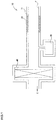
- Fig. 1 is a schematic view illustrating an air intake passage of an internal combustion engine
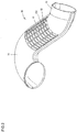
- Fig. 2 is a perspective view showing the air intake duct according to an embodiment of the present invention
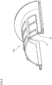
- Fig. 3 is a perspective view of a halved duct constituting the air intake duct according to the present embodiment
- Fig. 4 is a sectional view showing a structure of a silencing member.
- a resonator 30 is connected to an air intake duct 10 formed from a duct wall section 11 between an air intake port F and an air cleaner 40.
- the resonator 30 is constructed so as to have a volume calculated based on the resonance theory by Helmholtz for reducing noise having specific frequency, and a desired intake noise generated in the air intake passage can be reduced by setting a value of such volume to an appropriate value.
- the air intake duct 10 according to the present embodiment is provided with the duct wall section 11 formed with a silencing member 20 on the air intake port side F than the location of the resonator 30.
- the intake noise can be further effectively reduced. It is to be noted that if the intake noise can be sufficiently reduced only by the location of the silencing member 20, it is not absolutely necessary to locate the resonator 30.
- the air intake duct 10 of the present embodiment is provided with the duct wall section 11 formed with a resin material in form of tube. Further, since a part of the duct wall section 11 is formed from a grid-shaped frame 12 so as to provide a number of holes 13 to the duct wall section 11, and the holes 13 are closed by locating the silencing member 30 so as to cover such holes 13.
- the silencing member 20 is formed by an insert-molding process, the silencing member 20, and the duct wall section 11 and the grid-shaped frame 12 are not bonded together by immersing a synthetic resin material between fibers of the silencing member 20 and then solidifying them.
- the synthetic resin material is not invaded between the fibers of the silencing member 20, and the silencing member 20.
- the duct wall section 11 and the grid-shaped frame 12 are mutually joined by an anchor effect of the surface of the silencing member 20.
- the silencing member 20 may be wound up around an outer periphery of the air intake duct 10 so as to cover the holes 13 of the duct wall section 11.
- the duct wall section 11 to which the silencing member 20 is formed by the insert-molding process forms the intake duct 10 by halved duct parts 10a, 10a by means of butt-joining process.
- the silencing member 20 can be easily insert-molded to the duct wall section 11.
- end portions of the halved duct parts 10a in an air flow direction are joined to an engine side duct 14 and an intake side duct 15, respectively, to thereby form one tubular air intake duct 10.
- a bonding method by means of bonding agent such as vibration welding method, heat plate welding method, ultrasonic welding method and the like, and other than the above methods, a bonding method by means of bonding agent, a fastening method by means of bolt, a fitting method of the respective halved duct parts, and a die slide injection (DSI) method may be also utilized.
- vibration welding method heat plate welding method
- ultrasonic welding method ultrasonic welding method and the like
- the number of the holes 13 and area of the holes 13 may be changed appropriately in consideration of intake noise reducing or attenuating ability of the silencing member 20 to be used. Furthermore, as shown in Fig. 3 , since the silencing member 20 is formed through the insert-molding process so as to be flush in its surface with the inner peripheral surface of the duct wall section 11, the inner peripheral surface of the duct wall section 11 can be formed to be flat, and hence, fluid passing inside the air intake duct 10 can pass smoothly.
- a structure of the silencing member 20 will be described hereunder with reference to Fig. 4 .
- the silencing member 20 is provided with a surface layer 21 which is formed by impregnating a thermosetting resin to a non-woven fabric and a ventilation adjusting layer 22 which is formed of an extendable paper material having a rough surface formed in concave/convex shape.
- the surface layer 21 is located to both the outsides of front and back (inner and outer) surfaces of the silencing member 20 so as to interpose the ventilation adjusting layer 22 and an intermediate layer 23 therebetween.
- the non-woven fabric used for the surface layer 21 has a base material formed of various fabrics such as aramid fiber, imide fiber, polyvinylchloride fiber, phenol fiber, rayon fiber, polyester fiber, polypropylene fiber, polyamide series fiber, acrylic acid fiber, carbon fiber, glass fiber, alumina fiber (ceramic fiber), boron fiber, novoride fiber, fluorine fiber, metallic fiber or like.
- thermosetting resin impregnated to the non-woven fabric there may be used, for example, urethane resin, melamine resin, thermosetting-type acryl resin, thermosetting-type acryl resin particularly cured by forming ester-link through heating process, urethane resin, epoxy resin, thermosetting-type polyester and the like.
- the ventilation adjusting layer 22 is formed of an extendable paper material as described above.
- the extendable paper material may be formed from: a crape-treated paper having wrinkled surface shape (wrinkled convex/concave shape); an embossed paper having a surface on which a number of projections are formed, and an embossed-crape-treated paper having a surface on which wrinkles and a number of projections are formed.
- a pulp used for the extendable paper material there may be provided, for example, hardwood pulp, softwood pulp, hemp pulp, kenaf pulp, bamboo pulp, esparto pulp, bagusse pulp, and reedy pulp.
- synthetic resin may be mixed by about 1 to 50% in amount.
- the intermediate layer 23 is interposed for adjusting the ventilation resistance of the silencing member 20 in a manner of being sandwiched between a pair of ventilation adjusting layers 22.
- the intermediate layer 23 is a laminated layer formed of the same substance as that of the surface layer 21.
- the silencing member 20 is composed of, as shown in Fig. 4 , the intermediate layer 23, a pair of ventilation layers 22 between which the intermediate layer 23 is interposed, and the surface layers 21 which are further disposed on the outer surfaces of the ventilation layers 22.
- Such laminated structure is thereafter subjected to heat-plate fusing by means of hot pressing process to thereby provide an integral layer structure.
- a bonding agent may be interposed, as occasion demands, between the surface layer 21 and the ventilation adjusting layer 22 and between the ventilation adjusting layer 22 and the intermediate layer 23.
- acrylic resin series bonding agent acrylic resin series bonding agent, urethane resin series bonding agent, epoxy resin series bonding agent, vinyl chloride resin solvent series bonding agent, chloroprene rubber series bonding agent, cyanoacrylate series bonding agent, silicone series bonding agent, modified silicone series bonding agent, resorcinol series bonding agent and the like may be used.
- the silencing member 20 according to the present embodiment is adjusted so as to have a thickness of 1-3 mm after the hot-pressing process and ventilation resistance of 1-4 kPa ⁇ s/m.
- the silencing member 20 of the present embodiment is provided with the intermediate layer 23 formed of the same substance as that of the surface layer 21 for adjusting the ventilation resistance, it is possible to prevent manufacturing cost from increasing and to achieve high intake noise attenuation effect.
- Figs. 5 to 8 represent results of analyzing the frequencies and the silenced amounts by the air intake ducts according to the present embodiment
- a conventional air intake duct having silencing function formed by two tubular pipes are bonded by means of belt-shaped felt having silencing function (Comparative Example 1) and an air intake duct having no silencing function (Comparative Example 2), and the Examples shown in Figs. 5 to 8 are adjusted in their ventilation resistances to 1.11 kPa ⁇ s/m, 1.51 kPa ⁇ s/m, 1.63 kPa ⁇ s/m, and 1.98 kPa ⁇ s/m, respectively.
- silenced amount equal to or more than that in the Comparative Example 1 in comparison with the Comparative Example 2 could be achieved in all the frequency bands (or frequency band ranges).
- the ventilation resistance is adjusted to 1.11kPa ⁇ s/m, it is found that particularly large silenced amount was obtained in comparison with the Comparative Example 1.
- the ventilation resistance is set to be not less than 1kPa ⁇ s/m.
- the upper limit of the ventilation resistance is set to about 4kPa ⁇ s/m, more preferably, to about 2kPa ⁇ s/m.
- Fig. 9 represents analysis result according to measurement of silenced amount in a wider frequency band range with respect to a conventional air intake duct (Comparative Example 2) having no silencing function.
- the air intake duct according to the present embodiment achieves an increased silenced amount in a high frequency band range (4 to 16kHz).
- the air intake duct according to the present invention can also achieve higher silencing function to noise or sound in the high frequency band range.
- the duct wall section 11 is formed from the frame 12 in form of grid to thereby form hole portions 13, the duct wall section 11 may be formed from a punched metal plate having a plurality holes or formed from net-shaped material.
- the air intake duct 10 according to the present embodiment is applicable to an intake duct for introducing external air into an internal combustion engine
- the air intake duct 10 of the present embodiment is not limited to such an air intake duct and it may be applied to an air intake duct for introducing external air for cooling an alternate power supply such as fuel cell or battery mounted to a vehicle body.
- noise to be absorbed or silenced is a rotating noise or wind noise of a fan for introducing external air, which is a noise having frequency higher than that of an intake air noise generated from an internal combustion engine.
- the silencing member 20 is applied only to the linear (straight) portion of the duct wall section 11, the silencing member 20 may be applied to the curved portion of the air intake duct 10. It is thus apparent that such alternation and improved modification may be included in the technical scope of the present invention as is apparent from the scope of the appended claims.
Landscapes
- Engineering & Computer Science (AREA)
- Chemical & Material Sciences (AREA)
- Combustion & Propulsion (AREA)
- Mechanical Engineering (AREA)
- General Engineering & Computer Science (AREA)
- Manufacturing & Machinery (AREA)
- Textile Engineering (AREA)
- Duct Arrangements (AREA)
- Exhaust Silencers (AREA)
- Rigid Pipes And Flexible Pipes (AREA)
Claims (5)
- Conduit d'admission d'air (10) présentant une section paroi de conduit (11) réalisée dans une résine en forme de tube, et étant configuré de façon à introduire l'air extérieur dans un moteur à combustion interne (E) ou dans un système d'alimentation alternatif, dans lequel :- la section paroi de conduit (11) est dotée d'un élément silencieux (20) formé d'une stratification d'une couche de surface (21) formée d'un tissu non tissé imbibé de résine thermodurcissable, et d'une couche de réglage de ventilation (22) formée d'un matériau de papier extensible présentant une surface où sont formées une pluralité de parties concaves et convexes ;- l'élément silencieux (20) comprend au moins une paire de couches de surface (21) sur les surfaces avant et arrière d'une paire au moins des couches de réglage de ventilation (22), et une couche intermédiaire (23) est formée entre les couches de réglage de ventilation appariées (22), la couche intermédiaire (23) étant formée dans le même matériau que celui de la couche de surface (21) ;- la section paroi de conduit (11) est jointe de manière mutuelle par un effet d'ancrage de la surface de l'élément silencieux (20) ;- l'élément silencieux (20) est formé en faisant appel à un procédé de moulage par insertion de façon à ce que sa surface affleure la surface périphérique intérieure de la section paroi de conduit (11) ;- une partie de la section paroi de conduit (11) est formée à partir d'un bâti en forme de grille (12) de façon à fournir un certain nombre de trous (13) dans la section paroi de conduit (11), et les trous (13) sont fermés en plaçant l'élément silencieux (20) de manière à couvrir les trous (13) ; et- le bâti en forme de grille (12) se situe seulement à la surface périphérique extérieure de l'élément silencieux (20).
- Conduit d'admission d'air (10) selon la revendication 1, dans lequel la couche intermédiaire (23) est liée sur les couches de réglage de ventilation (22) au moyen d'un agent de liaison.
- Conduit d'admission d'air (10) selon la revendication 1 ou la revendication 2, dans lequel l'élément silencieux (20) présente une épaisseur comprise entre 1,0 mm et 3,0 mm, et dans lequel l'élément silencieux (20) présente une résistance de ventilation comprise entre 1,0 kPa • s / m et 4,0 kPa • s / m.
- Conduit d'admission d'air (10) selon l'une quelconque des revendications 1 à 3, dans lequel l'élément silencieux (20) est situé de façon à fermer les trous (13) formés dans la section paroi de conduit (11).
- Conduit d'admission d'air (10) selon l'une quelconque des revendications 1 à 4, dans lequel l'élément silencieux (20) est formé en faisant appel à un procédé de moulage par insertion, sur la section paroi de conduit (11).
Applications Claiming Priority (2)
| Application Number | Priority Date | Filing Date | Title |
|---|---|---|---|
| JP2011192723 | 2011-09-05 | ||
| PCT/JP2012/071959 WO2013035614A1 (fr) | 2011-09-05 | 2012-08-30 | Conduit d'aspiration |
Publications (3)
| Publication Number | Publication Date |
|---|---|
| EP2754881A1 EP2754881A1 (fr) | 2014-07-16 |
| EP2754881A4 EP2754881A4 (fr) | 2015-02-25 |
| EP2754881B1 true EP2754881B1 (fr) | 2017-05-24 |
Family
ID=47832061
Family Applications (1)
| Application Number | Title | Priority Date | Filing Date |
|---|---|---|---|
| EP12830796.4A Not-in-force EP2754881B1 (fr) | 2011-09-05 | 2012-08-30 | Conduit d'aspiration |
Country Status (5)
| Country | Link |
|---|---|
| US (1) | US20140190764A1 (fr) |
| EP (1) | EP2754881B1 (fr) |
| JP (1) | JP5934709B2 (fr) |
| ES (1) | ES2635425T3 (fr) |
| WO (1) | WO2013035614A1 (fr) |
Families Citing this family (17)
| Publication number | Priority date | Publication date | Assignee | Title |
|---|---|---|---|---|
| JP6504844B2 (ja) * | 2015-02-10 | 2019-04-24 | 株式会社マーレ フィルターシステムズ | 内燃機関の吸気音低減装置 |
| JP6449095B2 (ja) * | 2015-05-01 | 2019-01-09 | タイガースポリマー株式会社 | 通気ダクト |
| JP6418064B2 (ja) * | 2015-05-20 | 2018-11-07 | スズキ株式会社 | 燃料電池自動二輪車 |
| CN110267804A (zh) * | 2017-02-06 | 2019-09-20 | 泽菲罗斯有限公司 | 不可渗透的复合材料 |
| JP2018193969A (ja) * | 2017-05-22 | 2018-12-06 | トヨタ紡織株式会社 | 内燃機関の吸気ダクト |
| FR3067280B1 (fr) * | 2017-06-09 | 2019-07-19 | Novares France | Procede de fabrication d’un conduit d’admission d’air |
| JP6874612B2 (ja) * | 2017-09-07 | 2021-05-19 | トヨタ紡織株式会社 | 内燃機関の吸気系部品 |
| US11319907B2 (en) * | 2018-02-14 | 2022-05-03 | Toyota Boshoku Kabushiki Kaisha | Precleaner for internal combustion engine |
| DE102018122988A1 (de) * | 2018-09-19 | 2020-03-19 | Veritas Ag | Fluidleitung zum leiten eines fluids |
| JP7196791B2 (ja) * | 2019-07-05 | 2022-12-27 | トヨタ紡織株式会社 | 内燃機関のインレットダクト |
| JP2021017840A (ja) * | 2019-07-19 | 2021-02-15 | トヨタ紡織株式会社 | 内燃機関の吸気ダクト |
| JP2021050672A (ja) * | 2019-09-25 | 2021-04-01 | 株式会社Roki | 吸気ダクト |
| JP7314812B2 (ja) * | 2020-01-28 | 2023-07-26 | トヨタ紡織株式会社 | 内燃機関の吸気ダクト |
| US11662048B2 (en) * | 2020-03-30 | 2023-05-30 | Toyota Motor Engineering & Manufacturing North America, Inc. | Compact duct sound absorber |
| CN115142997A (zh) * | 2022-06-27 | 2022-10-04 | 恒勃控股股份有限公司 | 一种车用防水消音脏进气管及其生产工艺 |
| IT202200015852A1 (it) * | 2022-07-27 | 2024-01-27 | Zrc Motorcycle Srl | Collettore d’aspirazione e procedimento per la realizzazione di detto collettore di aspirazione |
| FR3144226A1 (fr) | 2022-12-23 | 2024-06-28 | Sogefi Filtration | Agencement avec insert d’attenuation sonore pour circuit d’air d’admission moteur et methode d’assemblage |
Citations (3)
| Publication number | Priority date | Publication date | Assignee | Title |
|---|---|---|---|---|
| US20040187826A1 (en) * | 2003-03-27 | 2004-09-30 | Hitoshi Kino | Air intake apparatus and manufacturing method therefor |
| JP2008128168A (ja) * | 2006-11-24 | 2008-06-05 | Inoac Corp | ダクトとその製造方法 |
| JP2009270531A (ja) * | 2008-05-09 | 2009-11-19 | Toyota Boshoku Corp | 内燃機関の吸気ダクト及びその製造方法 |
Family Cites Families (31)
| Publication number | Priority date | Publication date | Assignee | Title |
|---|---|---|---|---|
| US2069413A (en) * | 1935-12-06 | 1937-02-02 | Burgess Lab Inc C F | Sound and vibration damping construction |
| US2192516A (en) * | 1937-05-28 | 1940-03-05 | Woodall Industries Inc | Insulation sheet material |
| US2419971A (en) * | 1943-06-05 | 1947-05-06 | Rumpf Herman | Padding and soundproofing material |
| GB957709A (en) * | 1959-02-16 | 1964-05-13 | Thermotank Plastic Engineering | Improvements in or relating to tubes and method of production thereof |
| US3176789A (en) * | 1962-01-26 | 1965-04-06 | Lighter Stephen | Acoustic panels |
| JPS51133922A (en) * | 1975-05-15 | 1976-11-20 | Nissan Motor | Sound insulation heat insulating material |
| DE7619090U1 (de) * | 1976-06-16 | 1976-11-18 | Dynamit Nobel Ag, 5210 Troisdorf | Selbsttragendes Formteil für Kraftfahrzeuge |
| JPS5312968A (en) * | 1976-07-21 | 1978-02-06 | Nissan Motor | Process for making packing material of corrugated cardboard |
| US4734308A (en) * | 1986-10-27 | 1988-03-29 | Corra-Board Products Co., Inc. | High strength paperboard panel |
| US5057176A (en) * | 1988-05-10 | 1991-10-15 | Manville Corporation | Method of forming corrugated paperboard automotive liner |
| US4886696A (en) * | 1988-05-10 | 1989-12-12 | Manville Corporation | Corrugated paperboard automotive liner |
| US4992320A (en) * | 1988-11-23 | 1991-02-12 | Courtaulds Automotive Products (Sa) (Pty.) Limited | Lamiantes for headlining |
| JPH07121566B2 (ja) * | 1990-12-26 | 1995-12-25 | 日本特殊塗料株式会社 | 深絞り可能な軽量防音材 |
| US5866235A (en) * | 1997-02-21 | 1999-02-02 | Eften, Inc. | All synthetic fiber interior trim substrate |
| US6553953B1 (en) * | 1998-04-09 | 2003-04-29 | Toyoda Gosei Co., Ltd. | Suction duct |
| TW576893B (en) * | 2000-05-17 | 2004-02-21 | Toyoda Gosei Kk | Air intake duct and manufacturing method therefor |
| JP2002004834A (ja) * | 2000-06-27 | 2002-01-09 | Kogi Corp | 内燃機関用吸音材 |
| JP2004062074A (ja) * | 2002-07-31 | 2004-02-26 | Toyota Motor Corp | 吸音装置 |
| JP2004332673A (ja) * | 2003-05-12 | 2004-11-25 | Mazda Motor Corp | 車両用内燃機関の吸気音低減装置 |
| DE102004029221A1 (de) * | 2004-06-16 | 2006-01-12 | Geiger Technik Gmbh | Vorrichtung zur Schalldämpfung und Vorrichtung zur Leitung eines Fluids |
| US7631726B2 (en) * | 2004-06-28 | 2009-12-15 | Mahle International Gmbh | Silencer for air induction system and high flow articulated coupling |
| JP5189972B2 (ja) * | 2005-03-18 | 2013-04-24 | チューメイン エンタープライジズ リミテッド | 音減衰流路デバイス |
| JP4552820B2 (ja) * | 2005-09-26 | 2010-09-29 | 豊田合成株式会社 | 吸気ダクト |
| JP4863294B2 (ja) * | 2007-05-30 | 2012-01-25 | 株式会社イノアックコーポレーション | 自動車用ダクト |
| CN101945762B (zh) * | 2008-02-14 | 2013-11-06 | 名古屋油化株式会社 | 吸音性表皮材及使用了该吸音性表皮材的吸音材 |
| JP5084618B2 (ja) * | 2008-06-03 | 2012-11-28 | 株式会社Roki | 吸気ダクト |
| WO2010038486A1 (fr) * | 2008-10-02 | 2010-04-08 | 名古屋油化株式会社 | Matériau d’absorption acoustique, matériau d’absorption acoustique multicouche, matériau d’absorption acoustique multicouche moulé, matériau intérieur d’absorption acoustique, et matériau d’absorption acoustique de revêtement de sol |
| TWI651455B (zh) * | 2009-01-14 | 2019-02-21 | Kuraray Co., Ltd | 隔音板、隔音構造及隔音方法 |
| DE102009033897A1 (de) * | 2009-07-20 | 2011-01-27 | Röchling Automotive AG & Co. KG | Luft-Strömungskanal |
| US8230969B2 (en) * | 2010-05-18 | 2012-07-31 | Precision Fabrics Group, Inc. | Acoustic panels, apparatus and assemblies with airflow-resistive layers attached to sound incident surfaces |
| JP5793422B2 (ja) * | 2010-06-08 | 2015-10-14 | 株式会社イノアックコーポレーション | 吸気ダクト |
-
2012
- 2012-08-30 US US14/239,878 patent/US20140190764A1/en not_active Abandoned
- 2012-08-30 WO PCT/JP2012/071959 patent/WO2013035614A1/fr not_active Ceased
- 2012-08-30 EP EP12830796.4A patent/EP2754881B1/fr not_active Not-in-force
- 2012-08-30 JP JP2013532555A patent/JP5934709B2/ja not_active Expired - Fee Related
- 2012-08-30 ES ES12830796.4T patent/ES2635425T3/es active Active
Patent Citations (3)
| Publication number | Priority date | Publication date | Assignee | Title |
|---|---|---|---|---|
| US20040187826A1 (en) * | 2003-03-27 | 2004-09-30 | Hitoshi Kino | Air intake apparatus and manufacturing method therefor |
| JP2008128168A (ja) * | 2006-11-24 | 2008-06-05 | Inoac Corp | ダクトとその製造方法 |
| JP2009270531A (ja) * | 2008-05-09 | 2009-11-19 | Toyota Boshoku Corp | 内燃機関の吸気ダクト及びその製造方法 |
Also Published As
| Publication number | Publication date |
|---|---|
| EP2754881A1 (fr) | 2014-07-16 |
| US20140190764A1 (en) | 2014-07-10 |
| EP2754881A4 (fr) | 2015-02-25 |
| JP5934709B2 (ja) | 2016-06-15 |
| WO2013035614A1 (fr) | 2013-03-14 |
| JPWO2013035614A1 (ja) | 2015-03-23 |
| ES2635425T3 (es) | 2017-10-03 |
Similar Documents
| Publication | Publication Date | Title |
|---|---|---|
| EP2754881B1 (fr) | Conduit d'aspiration | |
| EP2998163B1 (fr) | Couvercle de moteur | |
| JP5084618B2 (ja) | 吸気ダクト | |
| CN102741539B (zh) | 进气设备 | |
| KR100674125B1 (ko) | 흡기 덕트 | |
| JP6642253B2 (ja) | 内燃機関のエアクリーナ | |
| JP6720819B2 (ja) | 吸気系部品 | |
| US9139142B2 (en) | Three-layer acoustic insulator | |
| US20180340499A1 (en) | Intake passage component for internal combustion engine | |
| US20040226772A1 (en) | Air intake apparatus | |
| US10500532B2 (en) | Air cleaner | |
| US10550802B2 (en) | Air cleaner for internal combustion engine | |
| JP2018035701A (ja) | エアクリーナ | |
| KR101978697B1 (ko) | 공명음 저감 타이어 및 그 제조방법 | |
| EP3798440A1 (fr) | Conduit d'admission | |
| CN215620461U (zh) | 一种用于汽车发动机舱的吸音隔热垫 | |
| CN104583574B (zh) | 车辆用进气导管 | |
| KR200387474Y1 (ko) | 흡기 덕트 | |
| JP2010122606A (ja) | 板状吸音部材および板状吸音部材生産方法 | |
| JP2021095896A (ja) | 吸気ダクト | |
| CN114830227A (zh) | 通气部件 | |
| JP2018035703A (ja) | 内燃機関のエアクリーナ |
Legal Events
| Date | Code | Title | Description |
|---|---|---|---|
| PUAI | Public reference made under article 153(3) epc to a published international application that has entered the european phase |
Free format text: ORIGINAL CODE: 0009012 |
|
| 17P | Request for examination filed |
Effective date: 20140213 |
|
| AK | Designated contracting states |
Kind code of ref document: A1 Designated state(s): AL AT BE BG CH CY CZ DE DK EE ES FI FR GB GR HR HU IE IS IT LI LT LU LV MC MK MT NL NO PL PT RO RS SE SI SK SM TR |
|
| DAX | Request for extension of the european patent (deleted) | ||
| A4 | Supplementary search report drawn up and despatched |
Effective date: 20150128 |
|
| RIC1 | Information provided on ipc code assigned before grant |
Ipc: F02M 35/12 20060101AFI20150122BHEP Ipc: F01N 13/08 20100101ALI20150122BHEP Ipc: B32B 29/08 20060101ALI20150122BHEP Ipc: B32B 5/26 20060101ALI20150122BHEP Ipc: F02M 35/10 20060101ALI20150122BHEP Ipc: B32B 27/10 20060101ALI20150122BHEP |
|
| 17Q | First examination report despatched |
Effective date: 20160503 |
|
| REG | Reference to a national code |
Ref country code: DE Ref legal event code: R079 Ref document number: 602012032851 Country of ref document: DE Free format text: PREVIOUS MAIN CLASS: F02M0035120000 Ipc: B32B0029020000 |
|
| GRAP | Despatch of communication of intention to grant a patent |
Free format text: ORIGINAL CODE: EPIDOSNIGR1 |
|
| RIC1 | Information provided on ipc code assigned before grant |
Ipc: F02M 35/12 20060101ALI20161116BHEP Ipc: B32B 5/02 20060101ALI20161116BHEP Ipc: B32B 29/02 20060101AFI20161116BHEP Ipc: B32B 29/08 20060101ALI20161116BHEP Ipc: F02M 35/10 20060101ALI20161116BHEP |
|
| INTG | Intention to grant announced |
Effective date: 20161214 |
|
| GRAS | Grant fee paid |
Free format text: ORIGINAL CODE: EPIDOSNIGR3 |
|
| GRAA | (expected) grant |
Free format text: ORIGINAL CODE: 0009210 |
|
| AK | Designated contracting states |
Kind code of ref document: B1 Designated state(s): AL AT BE BG CH CY CZ DE DK EE ES FI FR GB GR HR HU IE IS IT LI LT LU LV MC MK MT NL NO PL PT RO RS SE SI SK SM TR |
|
| REG | Reference to a national code |
Ref country code: GB Ref legal event code: FG4D |
|
| REG | Reference to a national code |
Ref country code: CH Ref legal event code: EP |
|
| REG | Reference to a national code |
Ref country code: IE Ref legal event code: FG4D |
|
| REG | Reference to a national code |
Ref country code: AT Ref legal event code: REF Ref document number: 895818 Country of ref document: AT Kind code of ref document: T Effective date: 20170615 |
|
| REG | Reference to a national code |
Ref country code: DE Ref legal event code: R096 Ref document number: 602012032851 Country of ref document: DE |
|
| REG | Reference to a national code |
Ref country code: RO Ref legal event code: EPE |
|
| REG | Reference to a national code |
Ref country code: FR Ref legal event code: PLFP Year of fee payment: 6 |
|
| REG | Reference to a national code |
Ref country code: NL Ref legal event code: MP Effective date: 20170524 |
|
| REG | Reference to a national code |
Ref country code: ES Ref legal event code: FG2A Ref document number: 2635425 Country of ref document: ES Kind code of ref document: T3 Effective date: 20171003 |
|
| REG | Reference to a national code |
Ref country code: LT Ref legal event code: MG4D |
|
| REG | Reference to a national code |
Ref country code: AT Ref legal event code: MK05 Ref document number: 895818 Country of ref document: AT Kind code of ref document: T Effective date: 20170524 |
|
| PG25 | Lapsed in a contracting state [announced via postgrant information from national office to epo] |
Ref country code: AT Free format text: LAPSE BECAUSE OF FAILURE TO SUBMIT A TRANSLATION OF THE DESCRIPTION OR TO PAY THE FEE WITHIN THE PRESCRIBED TIME-LIMIT Effective date: 20170524 Ref country code: GR Free format text: LAPSE BECAUSE OF FAILURE TO SUBMIT A TRANSLATION OF THE DESCRIPTION OR TO PAY THE FEE WITHIN THE PRESCRIBED TIME-LIMIT Effective date: 20170825 Ref country code: FI Free format text: LAPSE BECAUSE OF FAILURE TO SUBMIT A TRANSLATION OF THE DESCRIPTION OR TO PAY THE FEE WITHIN THE PRESCRIBED TIME-LIMIT Effective date: 20170524 Ref country code: LT Free format text: LAPSE BECAUSE OF FAILURE TO SUBMIT A TRANSLATION OF THE DESCRIPTION OR TO PAY THE FEE WITHIN THE PRESCRIBED TIME-LIMIT Effective date: 20170524 Ref country code: HR Free format text: LAPSE BECAUSE OF FAILURE TO SUBMIT A TRANSLATION OF THE DESCRIPTION OR TO PAY THE FEE WITHIN THE PRESCRIBED TIME-LIMIT Effective date: 20170524 Ref country code: NO Free format text: LAPSE BECAUSE OF FAILURE TO SUBMIT A TRANSLATION OF THE DESCRIPTION OR TO PAY THE FEE WITHIN THE PRESCRIBED TIME-LIMIT Effective date: 20170824 |
|
| PG25 | Lapsed in a contracting state [announced via postgrant information from national office to epo] |
Ref country code: RS Free format text: LAPSE BECAUSE OF FAILURE TO SUBMIT A TRANSLATION OF THE DESCRIPTION OR TO PAY THE FEE WITHIN THE PRESCRIBED TIME-LIMIT Effective date: 20170524 Ref country code: BG Free format text: LAPSE BECAUSE OF FAILURE TO SUBMIT A TRANSLATION OF THE DESCRIPTION OR TO PAY THE FEE WITHIN THE PRESCRIBED TIME-LIMIT Effective date: 20170824 Ref country code: NL Free format text: LAPSE BECAUSE OF FAILURE TO SUBMIT A TRANSLATION OF THE DESCRIPTION OR TO PAY THE FEE WITHIN THE PRESCRIBED TIME-LIMIT Effective date: 20170524 Ref country code: IS Free format text: LAPSE BECAUSE OF FAILURE TO SUBMIT A TRANSLATION OF THE DESCRIPTION OR TO PAY THE FEE WITHIN THE PRESCRIBED TIME-LIMIT Effective date: 20170924 Ref country code: LV Free format text: LAPSE BECAUSE OF FAILURE TO SUBMIT A TRANSLATION OF THE DESCRIPTION OR TO PAY THE FEE WITHIN THE PRESCRIBED TIME-LIMIT Effective date: 20170524 Ref country code: SE Free format text: LAPSE BECAUSE OF FAILURE TO SUBMIT A TRANSLATION OF THE DESCRIPTION OR TO PAY THE FEE WITHIN THE PRESCRIBED TIME-LIMIT Effective date: 20170524 |
|
| PG25 | Lapsed in a contracting state [announced via postgrant information from national office to epo] |
Ref country code: DK Free format text: LAPSE BECAUSE OF FAILURE TO SUBMIT A TRANSLATION OF THE DESCRIPTION OR TO PAY THE FEE WITHIN THE PRESCRIBED TIME-LIMIT Effective date: 20170524 Ref country code: SK Free format text: LAPSE BECAUSE OF FAILURE TO SUBMIT A TRANSLATION OF THE DESCRIPTION OR TO PAY THE FEE WITHIN THE PRESCRIBED TIME-LIMIT Effective date: 20170524 Ref country code: CZ Free format text: LAPSE BECAUSE OF FAILURE TO SUBMIT A TRANSLATION OF THE DESCRIPTION OR TO PAY THE FEE WITHIN THE PRESCRIBED TIME-LIMIT Effective date: 20170524 Ref country code: EE Free format text: LAPSE BECAUSE OF FAILURE TO SUBMIT A TRANSLATION OF THE DESCRIPTION OR TO PAY THE FEE WITHIN THE PRESCRIBED TIME-LIMIT Effective date: 20170524 |
|
| REG | Reference to a national code |
Ref country code: DE Ref legal event code: R097 Ref document number: 602012032851 Country of ref document: DE |
|
| PG25 | Lapsed in a contracting state [announced via postgrant information from national office to epo] |
Ref country code: SM Free format text: LAPSE BECAUSE OF FAILURE TO SUBMIT A TRANSLATION OF THE DESCRIPTION OR TO PAY THE FEE WITHIN THE PRESCRIBED TIME-LIMIT Effective date: 20170524 Ref country code: PL Free format text: LAPSE BECAUSE OF FAILURE TO SUBMIT A TRANSLATION OF THE DESCRIPTION OR TO PAY THE FEE WITHIN THE PRESCRIBED TIME-LIMIT Effective date: 20170524 Ref country code: IT Free format text: LAPSE BECAUSE OF FAILURE TO SUBMIT A TRANSLATION OF THE DESCRIPTION OR TO PAY THE FEE WITHIN THE PRESCRIBED TIME-LIMIT Effective date: 20170524 |
|
| REG | Reference to a national code |
Ref country code: CH Ref legal event code: PL |
|
| PG25 | Lapsed in a contracting state [announced via postgrant information from national office to epo] |
Ref country code: MC Free format text: LAPSE BECAUSE OF FAILURE TO SUBMIT A TRANSLATION OF THE DESCRIPTION OR TO PAY THE FEE WITHIN THE PRESCRIBED TIME-LIMIT Effective date: 20170524 |
|
| PLBE | No opposition filed within time limit |
Free format text: ORIGINAL CODE: 0009261 |
|
| STAA | Information on the status of an ep patent application or granted ep patent |
Free format text: STATUS: NO OPPOSITION FILED WITHIN TIME LIMIT |
|
| PG25 | Lapsed in a contracting state [announced via postgrant information from national office to epo] |
Ref country code: LI Free format text: LAPSE BECAUSE OF NON-PAYMENT OF DUE FEES Effective date: 20170831 Ref country code: CH Free format text: LAPSE BECAUSE OF NON-PAYMENT OF DUE FEES Effective date: 20170831 |
|
| 26N | No opposition filed |
Effective date: 20180227 |
|
| REG | Reference to a national code |
Ref country code: IE Ref legal event code: MM4A |
|
| PG25 | Lapsed in a contracting state [announced via postgrant information from national office to epo] |
Ref country code: SI Free format text: LAPSE BECAUSE OF FAILURE TO SUBMIT A TRANSLATION OF THE DESCRIPTION OR TO PAY THE FEE WITHIN THE PRESCRIBED TIME-LIMIT Effective date: 20170524 |
|
| REG | Reference to a national code |
Ref country code: BE Ref legal event code: MM Effective date: 20170831 |
|
| PG25 | Lapsed in a contracting state [announced via postgrant information from national office to epo] |
Ref country code: LU Free format text: LAPSE BECAUSE OF NON-PAYMENT OF DUE FEES Effective date: 20170830 |
|
| PG25 | Lapsed in a contracting state [announced via postgrant information from national office to epo] |
Ref country code: IE Free format text: LAPSE BECAUSE OF NON-PAYMENT OF DUE FEES Effective date: 20170830 |
|
| REG | Reference to a national code |
Ref country code: FR Ref legal event code: PLFP Year of fee payment: 7 |
|
| PG25 | Lapsed in a contracting state [announced via postgrant information from national office to epo] |
Ref country code: BE Free format text: LAPSE BECAUSE OF NON-PAYMENT OF DUE FEES Effective date: 20170831 |
|
| PG25 | Lapsed in a contracting state [announced via postgrant information from national office to epo] |
Ref country code: MT Free format text: LAPSE BECAUSE OF NON-PAYMENT OF DUE FEES Effective date: 20170830 |
|
| PG25 | Lapsed in a contracting state [announced via postgrant information from national office to epo] |
Ref country code: HU Free format text: LAPSE BECAUSE OF FAILURE TO SUBMIT A TRANSLATION OF THE DESCRIPTION OR TO PAY THE FEE WITHIN THE PRESCRIBED TIME-LIMIT; INVALID AB INITIO Effective date: 20120830 |
|
| PG25 | Lapsed in a contracting state [announced via postgrant information from national office to epo] |
Ref country code: CY Free format text: LAPSE BECAUSE OF NON-PAYMENT OF DUE FEES Effective date: 20170524 |
|
| PG25 | Lapsed in a contracting state [announced via postgrant information from national office to epo] |
Ref country code: MK Free format text: LAPSE BECAUSE OF FAILURE TO SUBMIT A TRANSLATION OF THE DESCRIPTION OR TO PAY THE FEE WITHIN THE PRESCRIBED TIME-LIMIT Effective date: 20170524 |
|
| PG25 | Lapsed in a contracting state [announced via postgrant information from national office to epo] |
Ref country code: TR Free format text: LAPSE BECAUSE OF FAILURE TO SUBMIT A TRANSLATION OF THE DESCRIPTION OR TO PAY THE FEE WITHIN THE PRESCRIBED TIME-LIMIT Effective date: 20170524 |
|
| PG25 | Lapsed in a contracting state [announced via postgrant information from national office to epo] |
Ref country code: PT Free format text: LAPSE BECAUSE OF FAILURE TO SUBMIT A TRANSLATION OF THE DESCRIPTION OR TO PAY THE FEE WITHIN THE PRESCRIBED TIME-LIMIT Effective date: 20170524 |
|
| PG25 | Lapsed in a contracting state [announced via postgrant information from national office to epo] |
Ref country code: AL Free format text: LAPSE BECAUSE OF FAILURE TO SUBMIT A TRANSLATION OF THE DESCRIPTION OR TO PAY THE FEE WITHIN THE PRESCRIBED TIME-LIMIT Effective date: 20170524 |
|
| PGFP | Annual fee paid to national office [announced via postgrant information from national office to epo] |
Ref country code: FR Payment date: 20210819 Year of fee payment: 10 |
|
| PGFP | Annual fee paid to national office [announced via postgrant information from national office to epo] |
Ref country code: GB Payment date: 20210820 Year of fee payment: 10 Ref country code: DE Payment date: 20210819 Year of fee payment: 10 Ref country code: RO Payment date: 20210820 Year of fee payment: 10 |
|
| PGFP | Annual fee paid to national office [announced via postgrant information from national office to epo] |
Ref country code: ES Payment date: 20211025 Year of fee payment: 10 |
|
| REG | Reference to a national code |
Ref country code: DE Ref legal event code: R119 Ref document number: 602012032851 Country of ref document: DE |
|
| GBPC | Gb: european patent ceased through non-payment of renewal fee |
Effective date: 20220830 |
|
| PG25 | Lapsed in a contracting state [announced via postgrant information from national office to epo] |
Ref country code: RO Free format text: LAPSE BECAUSE OF NON-PAYMENT OF DUE FEES Effective date: 20220830 |
|
| PG25 | Lapsed in a contracting state [announced via postgrant information from national office to epo] |
Ref country code: FR Free format text: LAPSE BECAUSE OF NON-PAYMENT OF DUE FEES Effective date: 20220831 Ref country code: DE Free format text: LAPSE BECAUSE OF NON-PAYMENT OF DUE FEES Effective date: 20230301 |
|
| REG | Reference to a national code |
Ref country code: ES Ref legal event code: FD2A Effective date: 20231003 |
|
| PG25 | Lapsed in a contracting state [announced via postgrant information from national office to epo] |
Ref country code: GB Free format text: LAPSE BECAUSE OF NON-PAYMENT OF DUE FEES Effective date: 20220830 Ref country code: ES Free format text: LAPSE BECAUSE OF NON-PAYMENT OF DUE FEES Effective date: 20220831 |