EP2756251B1 - Kapillarpumpen-wärmetransportvorrichtung - Google Patents
Kapillarpumpen-wärmetransportvorrichtung Download PDFInfo
- Publication number
- EP2756251B1 EP2756251B1 EP12756742.8A EP12756742A EP2756251B1 EP 2756251 B1 EP2756251 B1 EP 2756251B1 EP 12756742 A EP12756742 A EP 12756742A EP 2756251 B1 EP2756251 B1 EP 2756251B1
- Authority
- EP
- European Patent Office
- Prior art keywords
- reservoir
- evaporator
- inlet
- liquid phase
- phase
- Prior art date
- Legal status (The legal status is an assumption and is not a legal conclusion. Google has not performed a legal analysis and makes no representation as to the accuracy of the status listed.)
- Active
Links
Images


Classifications
-
- F—MECHANICAL ENGINEERING; LIGHTING; HEATING; WEAPONS; BLASTING
- F28—HEAT EXCHANGE IN GENERAL
- F28D—HEAT-EXCHANGE APPARATUS, NOT PROVIDED FOR IN ANOTHER SUBCLASS, IN WHICH THE HEAT-EXCHANGE MEDIA DO NOT COME INTO DIRECT CONTACT
- F28D15/00—Heat-exchange apparatus with the intermediate heat-transfer medium in closed tubes passing into or through the conduit walls ; Heat-exchange apparatus employing intermediate heat-transfer medium or bodies
- F28D15/02—Heat-exchange apparatus with the intermediate heat-transfer medium in closed tubes passing into or through the conduit walls ; Heat-exchange apparatus employing intermediate heat-transfer medium or bodies in which the medium condenses and evaporates, e.g. heat pipes
- F28D15/04—Heat-exchange apparatus with the intermediate heat-transfer medium in closed tubes passing into or through the conduit walls ; Heat-exchange apparatus employing intermediate heat-transfer medium or bodies in which the medium condenses and evaporates, e.g. heat pipes with tubes having a capillary structure
- F28D15/043—Heat-exchange apparatus with the intermediate heat-transfer medium in closed tubes passing into or through the conduit walls ; Heat-exchange apparatus employing intermediate heat-transfer medium or bodies in which the medium condenses and evaporates, e.g. heat pipes with tubes having a capillary structure forming loops, e.g. capillary pumped loops
-
- F—MECHANICAL ENGINEERING; LIGHTING; HEATING; WEAPONS; BLASTING
- F28—HEAT EXCHANGE IN GENERAL
- F28D—HEAT-EXCHANGE APPARATUS, NOT PROVIDED FOR IN ANOTHER SUBCLASS, IN WHICH THE HEAT-EXCHANGE MEDIA DO NOT COME INTO DIRECT CONTACT
- F28D15/00—Heat-exchange apparatus with the intermediate heat-transfer medium in closed tubes passing into or through the conduit walls ; Heat-exchange apparatus employing intermediate heat-transfer medium or bodies
- F28D15/02—Heat-exchange apparatus with the intermediate heat-transfer medium in closed tubes passing into or through the conduit walls ; Heat-exchange apparatus employing intermediate heat-transfer medium or bodies in which the medium condenses and evaporates, e.g. heat pipes
- F28D15/04—Heat-exchange apparatus with the intermediate heat-transfer medium in closed tubes passing into or through the conduit walls ; Heat-exchange apparatus employing intermediate heat-transfer medium or bodies in which the medium condenses and evaporates, e.g. heat pipes with tubes having a capillary structure
- F28D15/046—Heat-exchange apparatus with the intermediate heat-transfer medium in closed tubes passing into or through the conduit walls ; Heat-exchange apparatus employing intermediate heat-transfer medium or bodies in which the medium condenses and evaporates, e.g. heat pipes with tubes having a capillary structure characterised by the material or the construction of the capillary structure
Definitions
- the present invention relates to capillary pumping heat transport devices, in particular passive biphasic fluid loop devices.
- the device In addition, if the device is subjected to accelerations, it can occur a phenomenon of cold shock in the tank which suddenly lowers the pressure and deteriorates the performance.
- the hydraulic damping thus created, it avoids excessive liquid fluid movements in the tank when the device is subjected to accelerations, for example if it is on board a transport vehicle , and thus avoids a mixture in the tank that can lead to the effect of 'cold shock', namely a sudden lowering of the free surface temperature of the liquid in the tank which causes a drop in pressure and a decrease in efficiency of the loop.
- the partition in several separate volumes of liquid avoids a mixture that could occur due to sudden increases in thermal power, especially the case of startup.
- the figure 1 shows a capillary pumping heat transport device with a two-phase fluid loop.
- the device comprises an evaporator 1, having an inlet 1a and an outlet 1b , and a microporous mass 10 adapted to provide capillary pumping.
- the microporous mass 10 surrounds a blind central longitudinal recess 15 in communication with the inlet 1a to receive working fluid 9 in the liquid state from a reservoir 3.
- the evaporator 1 is thermally coupled to a heat source 11, such as a set comprising electronic power components or any other element that generates heat, for example by the Joule effect, or by any other process.
- a heat source 11 such as a set comprising electronic power components or any other element that generates heat, for example by the Joule effect, or by any other process.
- the cavities released by the evacuated vapor are filled with liquid sucked by the microporous mass 10 from the aforementioned central recess 15; it is the phenomenon of capillary pumping well known in itself.
- the fluid temperature 9 is lowered below its liquid-vapor equilibrium temperature, which is also called sub-cooling ('sub-cooling' in English) so that the fluid can not return to the vapor state without a consequent contribution heat.
- the vapor pressure pushes the liquid towards the outlet 2b of the condenser 2 which opens onto a second communication circuit 5, furthermore connected to the tank 3.
- the reservoir has at least one inlet and / or outlet orifice 31, here in this case on the figure 1 a separate inlet orifice 31a and outlet 31b , and the reservoir 3 has an internal volume 30, filled with the coolant 9.
- the working fluid 9 can be, for example, ammonia or any other suitable fluid, but it is preferable to choose methanol.
- the working fluid 9 is two-phase and is partly in liquid phase 9a and partly in vapor phase 9b. In an environment where gravity is exerted (vertical along Z), the gas phase portion 9b is located above the liquid phase portion 9a and a liquid-vapor interface 19 separates the two phases (free surface of the liquid in the liquid phase). tank).
- this pressure corresponds to the saturation pressure of the fluid at the temperature prevailing at the separation surface 19.
- the temperature of the liquid is generally lower than the temperature prevailing at the separation surface 19.
- the first and second fluid communication circuits 4,5 are preferably tubular conduits, but could be other types of fluid communication conduits or channels (rectangular, flexible conduits, etc.).
- the second fluid communication circuit 5 may be in the form of two separate independent conduits 5a, 5b (cf. Fig 1 ) or a single pipe with a 'T' connection 5c (cf. Fig 2 ).
- the second fluid communication circuit 5 connects the outlet of the condenser 2b to the inlet of the evaporator 1a, either indirectly via the reservoir (in the case of two independent conduits) or directly (case or a single driving with 'T').
- the reservoir In order to avoid mixing phenomena within the reservoir which are conducive to the phenomenon of 'cold shock', there are provided, inside the reservoir, several distinct volumes of liquid separated from each other but said distinct volumes remaining in fluid communication.
- in the reservoir can be arranged a plurality of internal walls 7 adapted to separate said several separate volumes.
- said several distinct volumes may be formed in a tight mesh structure (not shown in the figures), such as for example an iron straw type structure, or a sponge-type structure or a macroporous structure, or still a stack of hollow spheres pierced with small orifices.
- a tight mesh structure such as for example an iron straw type structure, or a sponge-type structure or a macroporous structure, or still a stack of hollow spheres pierced with small orifices.
- the reservoir comprises an inlet jet deflector 8 in the vicinity of the inlet orifice 31a or the inlet / outlet orifice 31 according to the configuration of the second conduit.
- This inlet jet deflector prevents a rapid arrival of liquid in the tank creates a bubbling or a current promoting the mixing of the liquid. It may be in the form of a downward U-shaped profile, or a bell or other shape creating a sufficient deflection of the path of the inlet jet.
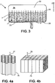
- the figure 3 shows a compartment structure 71, with vertical walls 7, that is to say oriented in the direction of gravity. It should be noted, however, that the walls may just as well be slightly or substantially inclined, as illustrated for example on the Figure 1 .
- the compartment structure is regular, i.e. a certain geometric pattern is repeated several times.
- the reservoir may have any shape, and in particular parallelepipedal or cylindrical.
- the compartment structure can be formed of stainless steel to give it good durability.
- the compartment structure may be formed of compatible plastic of the working fluid and in particular methanol; whereby it is compatible with this fluid commonly used for terrestrial applications, its life is satisfactory and its cost is low.
- said several distinct volumes communicate through passages of small section, preferably less than 1/10 of the largest section of the tank.
- the inner walls 7 have orifices 70 whose passage section is small, in order to create a hydraulic damping between the separate volumes of liquid.
- the passages between the separate volumes can also be located at the base of the compartments, without orifice on the height of the compartments.
- a grid 28 pierced with a plurality of small section holes allows the fluid to move between the compartments through a transfer chamber 29 located in the base zone 34 of the reservoir.
- This grid 28 also known as diffusion can advantageously serve as a support for the compartment structure 71.
- the height of the walls may be between 30% and 90% of the height of the tank, and will be chosen in particular so that the upper surface 19 of the liquid does not exceed the upper end of the walls 7.
- honeycomb structure of hexagonal mesh or a square mesh structure as illustrated respectively in FIGS. Figures 4a and 4b .
- Hexagonal compartments 77, (respectively square 78 ) communicate between their lower opening 76 (respectively 79 ).
- the plurality of walls may comprise walls oriented differently from each other.
- the size of the cells must not be too thin (less than one millimeter), otherwise the structure traps the liquid by capillarity and requires overfilling. to avoid drying the loop when starting in cold conditions or drops in power.
- the compartments are thus devoid of microporous structure, although the reservoir can form a macroporous structure.
- the compartment structure comprises a phase change material imparting a thermal inertia to said structure which contributes to limiting the sudden variations in temperature.
- the figure 5 is analogous to the figure 3 and shows a variant of the reservoir of the device with a liquid inlet at the bottom and on the side 35, which can simplify the inlet jet baffle 8.
- the inlet jet baffle 8 can then be reduced to a plate extending horizontally or at an extension pierced with a multitude of holes in the tube 5.
- the device may furthermore incidentally comprise a non-return member 6, arranged between the internal volume 30 of the reservoir and the microporous mass 10 of the evaporator, to prevent the liquid present in the evaporator from moving towards the volume inside the tank.
- This non-return member 6 makes it possible to prevent a liquid movement from the evaporator towards the reservoir when the boiling is triggered during the start-up phases of the system.
- this non-return member 6 may comprise a float (not shown in detail) whose density is slightly less than the fluid density in the liquid phase.
- the device may further comprise a power supply element 36, for example a heating element or pressurizing, located at the reservoir to control the pressurization of the loop during startup.
- a control system 'Ctrl' driver 38 in the case of a heating element, the supply of calories to this heating element 36, as a function of temperature information and / or pressure information delivered by sensors (not shown), in order to ensure the start of the two-phase loop.
- the heating element can be located both in the liquid phase and / or the vapor phase. Preferably, this element is located in the liquid phase and generates steam towards the upper part of the reservoir.
- the regulation with the heating element will be facilitated by the presence of a cold source in contact with the latter (ambient air, or other).
- this control system 'Ctrl' can also prepare the two-phase loop for an imminent and important arrival of calories on the evaporator, which makes it possible to anticipate the reaction of the two-phase loop with respect to the need for heat dissipation.
- the design of the loop can be optimized for large quantities of heat to be evacuated.
- the device is devoid of any mechanical pump although the invention does not exclude the presence of a mechanical booster pump.
Landscapes
- Engineering & Computer Science (AREA)
- General Engineering & Computer Science (AREA)
- Physics & Mathematics (AREA)
- Thermal Sciences (AREA)
- Sustainable Development (AREA)
- Mechanical Engineering (AREA)
- Life Sciences & Earth Sciences (AREA)
- Filling Or Discharging Of Gas Storage Vessels (AREA)
- Cooling Or The Like Of Semiconductors Or Solid State Devices (AREA)
- Fuel Cell (AREA)
- Jet Pumps And Other Pumps (AREA)
- Cooling Or The Like Of Electrical Apparatus (AREA)
- Central Heating Systems (AREA)
Claims (14)
- Vorrichtung zur Wärmeübertragung durch Kapillarpumpung, welche der Gravitation ausgesetzt und dazu angepasst ist, die Wärme von einer warmen Quelle (11) zu entnehmen und diese Wärme an eine kalte Quelle (12) mittels eines zweiphasigen Arbeitsfluids, welches in einem geschlossenen Hauptkreislauf enthalten ist, abzugeben, mit:- mindestens einem Verdampfer (1), der einen Eingang und einen Ausgang und eine mikroporöse Masse (10) hat, die dazu angepasst ist, eine Kapillarpumpung von Fluid in der Flüssigphase sicherzustellen,- mindestens einem Kondensator (2), der einen Eingang und einen Ausgang hat,- einem Reservoir (3), der ein inneres Volumen (30) und mindestens eine Eingangs- und/oder Ausgangsöffnung (31; 31 a, 31 b) hat, mit einem Gasphasenbereich, der sich über einem Flüssigphasenbereich befindet,- einem ersten Kommunikationskreis (4) für Fluid im Wesentlichen in der Dampfphase, welcher den Ausgang des Verdampfers und den Eingang des Kondensators verbindet,- einem zweiten Kommunikationskreis (5) für Fluid im Wesentlichen in der Flüssigphase, welcher den Ausgang des Kondensators am Reservoir und den Eingang des Verdampfers verbindet,dadurch gekennzeichnet, dass
das Reservoir (3) mehrere getrennte Flüssigphasenvolumina aufweist, wobei die getrennten Volumina in Fluidkommunikation bleiben, wobei das Reservoir eine Vielzahl von internen Wänden (7) aufweist, welche Kammern bilden, die zum Abtrennen der mehreren getrennten Flüssigphasenvolumina angepasst sind, wobei die mehreren getrennten Volumina über Durchgänge mit kleinem Querschnitt kommunizieren, um eine hydraulische Dämpfung zwischen den getrennten Flüssigphasenvolumina zu schaffen. - Vorrichtung nach Anspruch 1,
bei der die Flüssigphase nicht über das obere Ende der Wände (7) hinausgeht. - Vorrichtung nach einem der Ansprüche 1 bis 2,
bei der die Vielzahl von internen Wänden eine regelmäßige Kammerstruktur bildet. - Vorrichtung nach einem der Ansprüche 1 bis 3,
bei der das Reservoir eine makroporöse Struktur aufweist und die Kammern keine mikroporöse Struktur aufweisen. - Vorrichtung nach Anspruch 4,
die grundsätzlich der Erdgravitation ausgesetzt ist, bei der die Wände geneigte oder vertikale Trennwände bilden. - Vorrichtung nach einem der Ansprüche 4 bis 5,
bei der die Kammerstruktur die Form einer Bienenwabenstruktur annimmt. - Vorrichtung nach einem der Ansprüche 4 bis 6,
bei der die Kammerstruktur ein Phasenänderungsmaterial aufweist, welches eine thermische Trägheit verleiht. - Vorrichtung nach einem der Ansprüche 1 bis 7,
bei der das Reservoir einen Eingangsstrahldetektor (8) in Nachbarschaft der Eingangsöffnung aufweist. - Vorrichtung nach einem der Ansprüche 1 bis 8,
bei der das Reservoir angrenzend an den Verdampfer sein kann oder das Reservoir in den Verdampfer integriert sein kann. - Vorrichtung nach einem der Ansprüche 1 bis 9,
welche ein Rückschlagsorgan (6) aufweist, welches in dem inneren Volumen (30) des Reservoirs und der mikroporösen Masse (10) des Verdampfers angeordnet ist und angeordnet ist, um zu verhindern, dass in dem Verdampfer vorhandene Flüssigkeit nicht in Richtung des inneren Volumens des Reservoirs ausweicht. - Vorrichtung nach Anspruch 10,
die grundsätzlich der Erdgravitation ausgesetzt ist und bei der das Rückschlagsorgan einen Schwimmer (60) aufweist. - Vorrichtung zur Wärmeübertragung nach einem der vorherigen Ansprüche, dadurch gekennzeichnet, dass sie keine mechanische Pumpe aufweist.
- Vorrichtung nach einem der vorherigen Ansprüche,
welche ferner ein Energiezufuhrelement (36) auf dem Niveau des Reservoirs aufweist, um den Druckaufbau der Schleife beim Anfahren zu steuern. - Vorrichtung nach einem der vorherigen Ansprüche,
bei der der Querschnitt der Durchgänge mit kleinem Querschnitt kleiner als 1/10 des größten Querschnitts des Reservoirs ist.
Applications Claiming Priority (2)
| Application Number | Priority Date | Filing Date | Title |
|---|---|---|---|
| FR1158202A FR2979981B1 (fr) | 2011-09-14 | 2011-09-14 | Dispositif de transport de chaleur a pompage capillaire |
| PCT/EP2012/067752 WO2013037784A1 (fr) | 2011-09-14 | 2012-09-12 | Dispositif de transport de chaleur à pompage capillaire |
Publications (2)
| Publication Number | Publication Date |
|---|---|
| EP2756251A1 EP2756251A1 (de) | 2014-07-23 |
| EP2756251B1 true EP2756251B1 (de) | 2016-04-06 |
Family
ID=46829776
Family Applications (1)
| Application Number | Title | Priority Date | Filing Date |
|---|---|---|---|
| EP12756742.8A Active EP2756251B1 (de) | 2011-09-14 | 2012-09-12 | Kapillarpumpen-wärmetransportvorrichtung |
Country Status (7)
| Country | Link |
|---|---|
| US (1) | US9958214B2 (de) |
| EP (1) | EP2756251B1 (de) |
| JP (1) | JP6163490B2 (de) |
| CN (1) | CN104094074B (de) |
| ES (1) | ES2580402T3 (de) |
| FR (1) | FR2979981B1 (de) |
| WO (1) | WO2013037784A1 (de) |
Cited By (1)
| Publication number | Priority date | Publication date | Assignee | Title |
|---|---|---|---|---|
| RU2665754C1 (ru) * | 2017-06-22 | 2018-09-04 | Александр Михайлович Деревягин | Способ и устройство для теплопередачи |
Families Citing this family (7)
| Publication number | Priority date | Publication date | Assignee | Title |
|---|---|---|---|---|
| WO2014170907A2 (en) * | 2013-04-17 | 2014-10-23 | Venkata Sundereswar Rao Vempati | An energy efficient pressure less steam generator |
| FR3006431B1 (fr) * | 2013-05-29 | 2015-06-05 | Euro Heat Pipes | Dispositif de transport de chaleur a fluide diphasique |
| FR3009377B1 (fr) * | 2013-08-01 | 2018-10-19 | Euro Heat Pipes | Evaporateur a dispositif anti-retour pour boucle diphasique |
| CN103987235B (zh) * | 2014-04-14 | 2017-02-08 | 中国电子科技集团公司第十一研究所 | 一种散热方法和系统 |
| DE102015107473A1 (de) | 2015-05-12 | 2016-11-17 | Benteler Automobiltechnik Gmbh | Kraftfahrzeug-Wärmeübertragersystem |
| CN109029034A (zh) * | 2018-07-12 | 2018-12-18 | 南京航空航天大学 | 一种自驱动热管循环换热器 |
| WO2024238449A1 (en) * | 2023-05-12 | 2024-11-21 | The Regents Of The University Of California | Salt-rejecting continuous passive solar thermal desalination via thin-film condensation |
Family Cites Families (57)
| Publication number | Priority date | Publication date | Assignee | Title |
|---|---|---|---|---|
| US2366955A (en) | 1941-09-20 | 1945-01-09 | Servel Inc | Refrigeration |
| US3613778A (en) * | 1969-03-03 | 1971-10-19 | Northrop Corp | Flat plate heat pipe with structural wicks |
| DE2235792A1 (de) * | 1972-07-21 | 1974-01-31 | Dornier System Gmbh | Vorrichtung zur uebertragung von waermeenergie |
| US4061131A (en) * | 1975-11-24 | 1977-12-06 | Acme Engineering And Manufacturing Corporation | Heat transfer system particularly applicable to solar heating installations |
| US4286579A (en) | 1979-05-30 | 1981-09-01 | Barry Johnston | Closed loop solar collector system |
| US4296729A (en) * | 1980-02-04 | 1981-10-27 | Suntime, Inc. | Solar hot water heating system |
| JPH0230439B2 (ja) | 1985-01-30 | 1990-07-06 | Matsushita Electric Ind Co Ltd | Ruupushikihiitopaipu |
| FR2578638B1 (fr) * | 1985-03-08 | 1989-08-18 | Inst Francais Du Petrole | Procede de transfert de chaleur d'un fluide chaud a un fluide froid utilisant un fluide mixte comme agent caloporteur |
| JPS62233686A (ja) * | 1986-03-31 | 1987-10-14 | Yamato Seisakusho:Kk | 熱伝達装置 |
| JPH0718408B2 (ja) | 1986-06-23 | 1995-03-06 | 謙治 岡安 | 熱駆動ポンプ |
| FR2602851B1 (fr) | 1986-08-05 | 1988-11-18 | Nantes D Avignonet Philippe De | Systeme anti-retour pour toutes canalisations d'ecoulement non pulse ni aspire |
| US4830097A (en) * | 1987-07-15 | 1989-05-16 | The United States Of America As Represented By The Administrator Of The National Aeronautics And Space Administration | Space vehicle thermal rejection system |
| JP2657809B2 (ja) | 1987-12-22 | 1997-09-30 | 謙治 岡安 | 熱伝達装置 |
| JP2544433B2 (ja) * | 1988-03-31 | 1996-10-16 | 三機工業株式会社 | 冷媒自然循環式熱移動装置 |
| US4957157A (en) * | 1989-04-13 | 1990-09-18 | General Electric Co. | Two-phase thermal control system with a spherical wicked reservoir |
| JP2859927B2 (ja) | 1990-05-16 | 1999-02-24 | 株式会社東芝 | 冷却装置および温度制御装置 |
| JPH0490498A (ja) * | 1990-08-03 | 1992-03-24 | Mitsubishi Electric Corp | 熱伝達装置 |
| JP2801998B2 (ja) * | 1992-10-12 | 1998-09-21 | 富士通株式会社 | 電子機器の冷却装置 |
| US5816313A (en) * | 1994-02-25 | 1998-10-06 | Lockheed Martin Corporation | Pump, and earth-testable spacecraft capillary heat transport loop using augmentation pump and check valves |
| BE1009410A3 (fr) * | 1995-06-14 | 1997-03-04 | B C A Sa | Dispositif de transport de chaleur. |
| FR2752291B1 (fr) * | 1996-08-12 | 1998-09-25 | Centre Nat Etd Spatiales | Evaporateur capillaire pour boucle diphasique de transfert d'energie entre une source chaude et une source froide |
| JP3748984B2 (ja) | 1997-05-29 | 2006-02-22 | 本田技研工業株式会社 | 熱駆動式液圧発生装置 |
| JP2000241089A (ja) * | 1999-02-19 | 2000-09-08 | Mitsubishi Electric Corp | 蒸発器、吸熱器、熱輸送システム及び熱輸送方法 |
| US6227288B1 (en) * | 2000-05-01 | 2001-05-08 | The United States Of America As Represented By The Secretary Of The Air Force | Multifunctional capillary system for loop heat pipe statement of government interest |
| US8047268B1 (en) | 2002-10-02 | 2011-11-01 | Alliant Techsystems Inc. | Two-phase heat transfer system and evaporators and condensers for use in heat transfer systems |
| US7549461B2 (en) | 2000-06-30 | 2009-06-23 | Alliant Techsystems Inc. | Thermal management system |
| US8109325B2 (en) | 2000-06-30 | 2012-02-07 | Alliant Techsystems Inc. | Heat transfer system |
| US8136580B2 (en) | 2000-06-30 | 2012-03-20 | Alliant Techsystems Inc. | Evaporator for a heat transfer system |
| US6883588B1 (en) * | 2000-07-24 | 2005-04-26 | Space Systems/Loral, Inc. | Spacecraft radiator system using a heat pump |
| US6976527B2 (en) * | 2001-07-17 | 2005-12-20 | The Regents Of The University Of California | MEMS microcapillary pumped loop for chip-level temperature control |
| JP3661862B2 (ja) * | 2002-02-05 | 2005-06-22 | 独立行政法人 宇宙航空研究開発機構 | アキュムレータ |
| US7061446B1 (en) * | 2002-10-24 | 2006-06-13 | Raytheon Company | Method and apparatus for controlling temperature gradients within a structure being cooled |
| FR2851503B1 (fr) * | 2003-02-20 | 2008-02-15 | Appareil de ventilation, de chauffage et/ou de climatisation pour habitacle de vehicule automobile a refroidissement simultane d'air et d'un fluide caloporteur | |
| US7823629B2 (en) * | 2003-03-20 | 2010-11-02 | Thermal Corp. | Capillary assisted loop thermosiphon apparatus |
| US6865897B2 (en) * | 2003-07-10 | 2005-03-15 | Praxair Technology, Inc. | Method for providing refrigeration using capillary pumped liquid |
| US20050067146A1 (en) | 2003-09-02 | 2005-03-31 | Thayer John Gilbert | Two phase cooling system method for burn-in testing |
| JP2006064193A (ja) * | 2004-08-24 | 2006-03-09 | Mitsubishi Electric Corp | ループ熱交換熱輸送機器 |
| US20060065386A1 (en) | 2004-08-31 | 2006-03-30 | Mohammed Alam | Self-actuating and regulating heat exchange system |
| US6990816B1 (en) * | 2004-12-22 | 2006-01-31 | Advanced Cooling Technologies, Inc. | Hybrid capillary cooling apparatus |
| JP4381998B2 (ja) | 2005-02-24 | 2009-12-09 | 株式会社日立製作所 | 液冷システム |
| TWM284951U (en) * | 2005-09-21 | 2006-01-01 | Yen Sun Technology Corp | Heat dissipating device for an electronic device |
| CN2861836Y (zh) * | 2005-09-21 | 2007-01-24 | 上海海事大学 | 复合式热管除湿器 |
| TWI276396B (en) * | 2006-01-13 | 2007-03-11 | Ind Tech Res Inst | Closed-loop latent heat cooling method, and capillary force or non-nozzle module thereof |
| US7748436B1 (en) * | 2006-05-03 | 2010-07-06 | Advanced Cooling Technologies, Inc | Evaporator for capillary loop |
| US8627847B2 (en) | 2006-06-06 | 2014-01-14 | SIVAN Valves, LLC | Backflow preventer valve |
| US20080078530A1 (en) * | 2006-10-02 | 2008-04-03 | Foxconn Technology Co., Ltd. | Loop heat pipe with flexible artery mesh |
| US20080225489A1 (en) * | 2006-10-23 | 2008-09-18 | Teledyne Licensing, Llc | Heat spreader with high heat flux and high thermal conductivity |
| TWI318679B (en) * | 2007-05-16 | 2009-12-21 | Ind Tech Res Inst | Heat dissipation system with an plate evaporator |
| CN100460798C (zh) * | 2007-05-16 | 2009-02-11 | 中山大学 | 一种均温回路热管装置 |
| FR2919923B1 (fr) | 2007-08-08 | 2009-10-30 | Astrium Sas Soc Par Actions Si | Dispositif passif a micro boucle fluide a pompage capillaire |
| KR101055932B1 (ko) * | 2007-09-17 | 2011-08-09 | 바딤 아나토리에비치 포미트킨 | 히트 파이프 냉각기와 물 냉각기용 열 확산기 |
| US8196395B2 (en) | 2009-06-29 | 2012-06-12 | Lightsail Energy, Inc. | Compressed air energy storage system utilizing two-phase flow to facilitate heat exchange |
| FR2949642B1 (fr) | 2009-08-27 | 2012-05-04 | Alstom Transport Sa | Convertisseur de puissance electrique pour un vehicule ferroviaire |
| JP5287638B2 (ja) * | 2009-09-25 | 2013-09-11 | 富士通株式会社 | ループ型ヒートパイプ及び電子機器 |
| CN103189708B (zh) * | 2010-11-01 | 2015-04-01 | 富士通株式会社 | 环形热管以及利用该环形热管的电子设备 |
| CN102723316A (zh) * | 2011-03-29 | 2012-10-10 | 北京奇宏科技研发中心有限公司 | 环路热管结构 |
| FR2979982B1 (fr) * | 2011-09-14 | 2016-09-09 | Euro Heat Pipes | Dispositif de transport de chaleur a pompage capillaire |
-
2011
- 2011-09-14 FR FR1158202A patent/FR2979981B1/fr not_active Expired - Fee Related
-
2012
- 2012-09-12 EP EP12756742.8A patent/EP2756251B1/de active Active
- 2012-09-12 CN CN201280055587.5A patent/CN104094074B/zh not_active Expired - Fee Related
- 2012-09-12 WO PCT/EP2012/067752 patent/WO2013037784A1/fr not_active Ceased
- 2012-09-12 JP JP2014530188A patent/JP6163490B2/ja not_active Expired - Fee Related
- 2012-09-12 US US14/344,880 patent/US9958214B2/en not_active Expired - Fee Related
- 2012-09-12 ES ES12756742.8T patent/ES2580402T3/es active Active
Cited By (1)
| Publication number | Priority date | Publication date | Assignee | Title |
|---|---|---|---|---|
| RU2665754C1 (ru) * | 2017-06-22 | 2018-09-04 | Александр Михайлович Деревягин | Способ и устройство для теплопередачи |
Also Published As
| Publication number | Publication date |
|---|---|
| FR2979981A1 (fr) | 2013-03-15 |
| CN104094074A (zh) | 2014-10-08 |
| JP2014527153A (ja) | 2014-10-09 |
| JP6163490B2 (ja) | 2017-07-12 |
| US20150083373A1 (en) | 2015-03-26 |
| FR2979981B1 (fr) | 2016-09-09 |
| US9958214B2 (en) | 2018-05-01 |
| ES2580402T3 (es) | 2016-08-23 |
| EP2756251A1 (de) | 2014-07-23 |
| WO2013037784A1 (fr) | 2013-03-21 |
| CN104094074B (zh) | 2016-08-24 |
Similar Documents
| Publication | Publication Date | Title |
|---|---|---|
| EP2756251B1 (de) | Kapillarpumpen-wärmetransportvorrichtung | |
| EP2756252B1 (de) | Wärmeübertragungsvorrichtung mit kapillarpumpung | |
| EP2956729B1 (de) | Wärmetransportvorrichtung mit zweiphasiger flüssigkeit | |
| EP3004773A1 (de) | Wärmetransportvorrichtung mit zweiphasiger flüssigkeit | |
| EP3207324B1 (de) | Flaches wärmerohr mit reservoirfunktion | |
| EP0832411A1 (de) | Wärmeübertragungskreislauf mit kapillaren pumpen | |
| EP0782885A1 (de) | Sprühvorrichtung mit erhöhtem Wikungsgrad, insbesondere zur Erzeugung von Mikrotröpfchen von Wasser | |
| CN101862551A (zh) | 用于空间飞行器中的动力燃料罐的气泡捕捉器 | |
| FR3045793A1 (fr) | Pack de batterie refroidit par un materiau a changement de phase a pression constante | |
| EP2393714B1 (de) | Kryotank und trägerrakete mit einem solchen tank | |
| FR3016923A3 (fr) | Bocal de degazage et systeme de refroidissement pour vehicule automobile comprenant un tel bocal de degazage | |
| EP2476301B1 (de) | System zur thermischen steuerung eines geräts | |
| EP3640467A1 (de) | Turbotriebwerk mit thermoakustischem system | |
| EP1740898B1 (de) | Entwässerungsinstallation unter verwendung von zeolithen | |
| EP3027995B1 (de) | Verdampfer mit rückschlagvorrichtung für zweiphasigen kreislauf | |
| EP0022391A1 (de) | Gegenüber Beschleunigungen beständige kryostatische Vorrichtung | |
| CA2560670A1 (fr) | Panneau de refroidissement pour refrigerateur ou congelateur | |
| FR2706531A1 (fr) | Vase d'expansion pour circuit de refroidissement de moteur thermique. | |
| EP3435018B1 (de) | Wärmeenergie-speichervorrichtung, die einen internen tank und ein verteilungssystem eines wärmeübertragungsmittels umfasst | |
| FR2978819A1 (fr) | Desorbeur d'un dispositif de climatisation a carter rigidifie | |
| EP1918168B1 (de) | Behälter für hydraulische Kupplungs- und Bremsflüssigkeit mit Innenkammer | |
| FR3081214A1 (fr) | Evaporateur d'une boucle fluide et boucle fluide comprenant un tel evaporateur | |
| WO2013017439A1 (fr) | Desorbeur d'un dispositif de climatisation | |
| BE345688A (de) |
Legal Events
| Date | Code | Title | Description |
|---|---|---|---|
| PUAI | Public reference made under article 153(3) epc to a published international application that has entered the european phase |
Free format text: ORIGINAL CODE: 0009012 |
|
| 17P | Request for examination filed |
Effective date: 20140311 |
|
| AK | Designated contracting states |
Kind code of ref document: A1 Designated state(s): AL AT BE BG CH CY CZ DE DK EE ES FI FR GB GR HR HU IE IS IT LI LT LU LV MC MK MT NL NO PL PT RO RS SE SI SK SM TR |
|
| DAX | Request for extension of the european patent (deleted) | ||
| GRAP | Despatch of communication of intention to grant a patent |
Free format text: ORIGINAL CODE: EPIDOSNIGR1 |
|
| INTG | Intention to grant announced |
Effective date: 20151006 |
|
| GRAS | Grant fee paid |
Free format text: ORIGINAL CODE: EPIDOSNIGR3 |
|
| GRAA | (expected) grant |
Free format text: ORIGINAL CODE: 0009210 |
|
| AK | Designated contracting states |
Kind code of ref document: B1 Designated state(s): AL AT BE BG CH CY CZ DE DK EE ES FI FR GB GR HR HU IE IS IT LI LT LU LV MC MK MT NL NO PL PT RO RS SE SI SK SM TR |
|
| REG | Reference to a national code |
Ref country code: GB Ref legal event code: FG4D Free format text: NOT ENGLISH |
|
| REG | Reference to a national code |
Ref country code: AT Ref legal event code: REF Ref document number: 788285 Country of ref document: AT Kind code of ref document: T Effective date: 20160415 Ref country code: CH Ref legal event code: EP |
|
| REG | Reference to a national code |
Ref country code: IE Ref legal event code: FG4D Free format text: LANGUAGE OF EP DOCUMENT: FRENCH |
|
| REG | Reference to a national code |
Ref country code: DE Ref legal event code: R096 Ref document number: 602012016689 Country of ref document: DE |
|
| REG | Reference to a national code |
Ref country code: NL Ref legal event code: FP |
|
| REG | Reference to a national code |
Ref country code: FR Ref legal event code: PLFP Year of fee payment: 5 |
|
| REG | Reference to a national code |
Ref country code: SE Ref legal event code: TRGR |
|
| REG | Reference to a national code |
Ref country code: LT Ref legal event code: MG4D |
|
| REG | Reference to a national code |
Ref country code: AT Ref legal event code: MK05 Ref document number: 788285 Country of ref document: AT Kind code of ref document: T Effective date: 20160406 |
|
| REG | Reference to a national code |
Ref country code: ES Ref legal event code: FG2A Ref document number: 2580402 Country of ref document: ES Kind code of ref document: T3 Effective date: 20160823 |
|
| PG25 | Lapsed in a contracting state [announced via postgrant information from national office to epo] |
Ref country code: NO Free format text: LAPSE BECAUSE OF FAILURE TO SUBMIT A TRANSLATION OF THE DESCRIPTION OR TO PAY THE FEE WITHIN THE PRESCRIBED TIME-LIMIT Effective date: 20160706 Ref country code: LT Free format text: LAPSE BECAUSE OF FAILURE TO SUBMIT A TRANSLATION OF THE DESCRIPTION OR TO PAY THE FEE WITHIN THE PRESCRIBED TIME-LIMIT Effective date: 20160406 Ref country code: IS Free format text: LAPSE BECAUSE OF FAILURE TO SUBMIT A TRANSLATION OF THE DESCRIPTION OR TO PAY THE FEE WITHIN THE PRESCRIBED TIME-LIMIT Effective date: 20160806 Ref country code: PL Free format text: LAPSE BECAUSE OF FAILURE TO SUBMIT A TRANSLATION OF THE DESCRIPTION OR TO PAY THE FEE WITHIN THE PRESCRIBED TIME-LIMIT Effective date: 20160406 Ref country code: FI Free format text: LAPSE BECAUSE OF FAILURE TO SUBMIT A TRANSLATION OF THE DESCRIPTION OR TO PAY THE FEE WITHIN THE PRESCRIBED TIME-LIMIT Effective date: 20160406 |
|
| PG25 | Lapsed in a contracting state [announced via postgrant information from national office to epo] |
Ref country code: LV Free format text: LAPSE BECAUSE OF FAILURE TO SUBMIT A TRANSLATION OF THE DESCRIPTION OR TO PAY THE FEE WITHIN THE PRESCRIBED TIME-LIMIT Effective date: 20160406 Ref country code: PT Free format text: LAPSE BECAUSE OF FAILURE TO SUBMIT A TRANSLATION OF THE DESCRIPTION OR TO PAY THE FEE WITHIN THE PRESCRIBED TIME-LIMIT Effective date: 20160808 Ref country code: HR Free format text: LAPSE BECAUSE OF FAILURE TO SUBMIT A TRANSLATION OF THE DESCRIPTION OR TO PAY THE FEE WITHIN THE PRESCRIBED TIME-LIMIT Effective date: 20160406 Ref country code: GR Free format text: LAPSE BECAUSE OF FAILURE TO SUBMIT A TRANSLATION OF THE DESCRIPTION OR TO PAY THE FEE WITHIN THE PRESCRIBED TIME-LIMIT Effective date: 20160707 Ref country code: AT Free format text: LAPSE BECAUSE OF FAILURE TO SUBMIT A TRANSLATION OF THE DESCRIPTION OR TO PAY THE FEE WITHIN THE PRESCRIBED TIME-LIMIT Effective date: 20160406 Ref country code: RS Free format text: LAPSE BECAUSE OF FAILURE TO SUBMIT A TRANSLATION OF THE DESCRIPTION OR TO PAY THE FEE WITHIN THE PRESCRIBED TIME-LIMIT Effective date: 20160406 |
|
| REG | Reference to a national code |
Ref country code: DE Ref legal event code: R097 Ref document number: 602012016689 Country of ref document: DE |
|
| PG25 | Lapsed in a contracting state [announced via postgrant information from national office to epo] |
Ref country code: DK Free format text: LAPSE BECAUSE OF FAILURE TO SUBMIT A TRANSLATION OF THE DESCRIPTION OR TO PAY THE FEE WITHIN THE PRESCRIBED TIME-LIMIT Effective date: 20160406 Ref country code: RO Free format text: LAPSE BECAUSE OF FAILURE TO SUBMIT A TRANSLATION OF THE DESCRIPTION OR TO PAY THE FEE WITHIN THE PRESCRIBED TIME-LIMIT Effective date: 20160406 Ref country code: SK Free format text: LAPSE BECAUSE OF FAILURE TO SUBMIT A TRANSLATION OF THE DESCRIPTION OR TO PAY THE FEE WITHIN THE PRESCRIBED TIME-LIMIT Effective date: 20160406 Ref country code: CZ Free format text: LAPSE BECAUSE OF FAILURE TO SUBMIT A TRANSLATION OF THE DESCRIPTION OR TO PAY THE FEE WITHIN THE PRESCRIBED TIME-LIMIT Effective date: 20160406 Ref country code: EE Free format text: LAPSE BECAUSE OF FAILURE TO SUBMIT A TRANSLATION OF THE DESCRIPTION OR TO PAY THE FEE WITHIN THE PRESCRIBED TIME-LIMIT Effective date: 20160406 |
|
| PLBE | No opposition filed within time limit |
Free format text: ORIGINAL CODE: 0009261 |
|
| STAA | Information on the status of an ep patent application or granted ep patent |
Free format text: STATUS: NO OPPOSITION FILED WITHIN TIME LIMIT |
|
| PG25 | Lapsed in a contracting state [announced via postgrant information from national office to epo] |
Ref country code: SM Free format text: LAPSE BECAUSE OF FAILURE TO SUBMIT A TRANSLATION OF THE DESCRIPTION OR TO PAY THE FEE WITHIN THE PRESCRIBED TIME-LIMIT Effective date: 20160406 |
|
| 26N | No opposition filed |
Effective date: 20170110 |
|
| PG25 | Lapsed in a contracting state [announced via postgrant information from national office to epo] |
Ref country code: MC Free format text: LAPSE BECAUSE OF FAILURE TO SUBMIT A TRANSLATION OF THE DESCRIPTION OR TO PAY THE FEE WITHIN THE PRESCRIBED TIME-LIMIT Effective date: 20160406 |
|
| REG | Reference to a national code |
Ref country code: CH Ref legal event code: PL |
|
| PG25 | Lapsed in a contracting state [announced via postgrant information from national office to epo] |
Ref country code: SI Free format text: LAPSE BECAUSE OF FAILURE TO SUBMIT A TRANSLATION OF THE DESCRIPTION OR TO PAY THE FEE WITHIN THE PRESCRIBED TIME-LIMIT Effective date: 20160406 |
|
| REG | Reference to a national code |
Ref country code: IE Ref legal event code: MM4A |
|
| PG25 | Lapsed in a contracting state [announced via postgrant information from national office to epo] |
Ref country code: CH Free format text: LAPSE BECAUSE OF NON-PAYMENT OF DUE FEES Effective date: 20160930 Ref country code: IE Free format text: LAPSE BECAUSE OF NON-PAYMENT OF DUE FEES Effective date: 20160912 Ref country code: LI Free format text: LAPSE BECAUSE OF NON-PAYMENT OF DUE FEES Effective date: 20160930 |
|
| REG | Reference to a national code |
Ref country code: FR Ref legal event code: PLFP Year of fee payment: 6 |
|
| PG25 | Lapsed in a contracting state [announced via postgrant information from national office to epo] |
Ref country code: LU Free format text: LAPSE BECAUSE OF NON-PAYMENT OF DUE FEES Effective date: 20160912 |
|
| PG25 | Lapsed in a contracting state [announced via postgrant information from national office to epo] |
Ref country code: HU Free format text: LAPSE BECAUSE OF FAILURE TO SUBMIT A TRANSLATION OF THE DESCRIPTION OR TO PAY THE FEE WITHIN THE PRESCRIBED TIME-LIMIT; INVALID AB INITIO Effective date: 20120912 |
|
| PG25 | Lapsed in a contracting state [announced via postgrant information from national office to epo] |
Ref country code: MT Free format text: LAPSE BECAUSE OF FAILURE TO SUBMIT A TRANSLATION OF THE DESCRIPTION OR TO PAY THE FEE WITHIN THE PRESCRIBED TIME-LIMIT Effective date: 20160406 Ref country code: MK Free format text: LAPSE BECAUSE OF FAILURE TO SUBMIT A TRANSLATION OF THE DESCRIPTION OR TO PAY THE FEE WITHIN THE PRESCRIBED TIME-LIMIT Effective date: 20160406 Ref country code: CY Free format text: LAPSE BECAUSE OF FAILURE TO SUBMIT A TRANSLATION OF THE DESCRIPTION OR TO PAY THE FEE WITHIN THE PRESCRIBED TIME-LIMIT Effective date: 20160406 |
|
| PG25 | Lapsed in a contracting state [announced via postgrant information from national office to epo] |
Ref country code: BG Free format text: LAPSE BECAUSE OF FAILURE TO SUBMIT A TRANSLATION OF THE DESCRIPTION OR TO PAY THE FEE WITHIN THE PRESCRIBED TIME-LIMIT Effective date: 20160406 |
|
| REG | Reference to a national code |
Ref country code: FR Ref legal event code: PLFP Year of fee payment: 7 |
|
| PG25 | Lapsed in a contracting state [announced via postgrant information from national office to epo] |
Ref country code: AL Free format text: LAPSE BECAUSE OF FAILURE TO SUBMIT A TRANSLATION OF THE DESCRIPTION OR TO PAY THE FEE WITHIN THE PRESCRIBED TIME-LIMIT Effective date: 20160406 Ref country code: TR Free format text: LAPSE BECAUSE OF FAILURE TO SUBMIT A TRANSLATION OF THE DESCRIPTION OR TO PAY THE FEE WITHIN THE PRESCRIBED TIME-LIMIT Effective date: 20160406 |
|
| PGFP | Annual fee paid to national office [announced via postgrant information from national office to epo] |
Ref country code: IT Payment date: 20210910 Year of fee payment: 10 |
|
| PGFP | Annual fee paid to national office [announced via postgrant information from national office to epo] |
Ref country code: GB Payment date: 20210928 Year of fee payment: 10 Ref country code: DE Payment date: 20210908 Year of fee payment: 10 Ref country code: SE Payment date: 20210916 Year of fee payment: 10 Ref country code: BE Payment date: 20210927 Year of fee payment: 10 |
|
| PGFP | Annual fee paid to national office [announced via postgrant information from national office to epo] |
Ref country code: ES Payment date: 20211005 Year of fee payment: 10 |
|
| PGFP | Annual fee paid to national office [announced via postgrant information from national office to epo] |
Ref country code: NL Payment date: 20220823 Year of fee payment: 11 |
|
| REG | Reference to a national code |
Ref country code: DE Ref legal event code: R119 Ref document number: 602012016689 Country of ref document: DE |
|
| REG | Reference to a national code |
Ref country code: SE Ref legal event code: EUG |
|
| GBPC | Gb: european patent ceased through non-payment of renewal fee |
Effective date: 20220912 |
|
| REG | Reference to a national code |
Ref country code: BE Ref legal event code: MM Effective date: 20220930 |
|
| PG25 | Lapsed in a contracting state [announced via postgrant information from national office to epo] |
Ref country code: DE Free format text: LAPSE BECAUSE OF NON-PAYMENT OF DUE FEES Effective date: 20230401 |
|
| PG25 | Lapsed in a contracting state [announced via postgrant information from national office to epo] |
Ref country code: SE Free format text: LAPSE BECAUSE OF NON-PAYMENT OF DUE FEES Effective date: 20220913 |
|
| PG25 | Lapsed in a contracting state [announced via postgrant information from national office to epo] |
Ref country code: BE Free format text: LAPSE BECAUSE OF NON-PAYMENT OF DUE FEES Effective date: 20220930 |
|
| REG | Reference to a national code |
Ref country code: ES Ref legal event code: FD2A Effective date: 20231027 |
|
| PG25 | Lapsed in a contracting state [announced via postgrant information from national office to epo] |
Ref country code: IT Free format text: LAPSE BECAUSE OF NON-PAYMENT OF DUE FEES Effective date: 20220912 Ref country code: GB Free format text: LAPSE BECAUSE OF NON-PAYMENT OF DUE FEES Effective date: 20220912 |
|
| PG25 | Lapsed in a contracting state [announced via postgrant information from national office to epo] |
Ref country code: ES Free format text: LAPSE BECAUSE OF NON-PAYMENT OF DUE FEES Effective date: 20220913 |
|
| PG25 | Lapsed in a contracting state [announced via postgrant information from national office to epo] |
Ref country code: ES Free format text: LAPSE BECAUSE OF NON-PAYMENT OF DUE FEES Effective date: 20220913 |
|
| REG | Reference to a national code |
Ref country code: NL Ref legal event code: MM Effective date: 20231001 |
|
| PG25 | Lapsed in a contracting state [announced via postgrant information from national office to epo] |
Ref country code: NL Free format text: LAPSE BECAUSE OF NON-PAYMENT OF DUE FEES Effective date: 20231001 |
|
| PG25 | Lapsed in a contracting state [announced via postgrant information from national office to epo] |
Ref country code: NL Free format text: LAPSE BECAUSE OF NON-PAYMENT OF DUE FEES Effective date: 20231001 |
|
| PGFP | Annual fee paid to national office [announced via postgrant information from national office to epo] |
Ref country code: FR Payment date: 20250821 Year of fee payment: 14 |