EP2756329B1 - Capteur de radar imageur à lobe d'antenne étroit et zone de détection angulaire large - Google Patents
Capteur de radar imageur à lobe d'antenne étroit et zone de détection angulaire large Download PDFInfo
- Publication number
- EP2756329B1 EP2756329B1 EP12769898.3A EP12769898A EP2756329B1 EP 2756329 B1 EP2756329 B1 EP 2756329B1 EP 12769898 A EP12769898 A EP 12769898A EP 2756329 B1 EP2756329 B1 EP 2756329B1
- Authority
- EP
- European Patent Office
- Prior art keywords
- antennas
- antenna
- transmitting antennas
- receiving
- distance
- Prior art date
- Legal status (The legal status is an assumption and is not a legal conclusion. Google has not performed a legal analysis and makes no representation as to the accuracy of the status listed.)
- Active
Links
Images




Classifications
-
- G—PHYSICS
- G01—MEASURING; TESTING
- G01S—RADIO DIRECTION-FINDING; RADIO NAVIGATION; DETERMINING DISTANCE OR VELOCITY BY USE OF RADIO WAVES; LOCATING OR PRESENCE-DETECTING BY USE OF THE REFLECTION OR RERADIATION OF RADIO WAVES; ANALOGOUS ARRANGEMENTS USING OTHER WAVES
- G01S13/00—Systems using the reflection or reradiation of radio waves, e.g. radar systems; Analogous systems using reflection or reradiation of waves whose nature or wavelength is irrelevant or unspecified
- G01S13/02—Systems using reflection of radio waves, e.g. primary radar systems; Analogous systems
- G01S13/06—Systems determining position data of a target
-
- G—PHYSICS
- G01—MEASURING; TESTING
- G01S—RADIO DIRECTION-FINDING; RADIO NAVIGATION; DETERMINING DISTANCE OR VELOCITY BY USE OF RADIO WAVES; LOCATING OR PRESENCE-DETECTING BY USE OF THE REFLECTION OR RERADIATION OF RADIO WAVES; ANALOGOUS ARRANGEMENTS USING OTHER WAVES
- G01S7/00—Details of systems according to groups G01S13/00, G01S15/00, G01S17/00
- G01S7/02—Details of systems according to groups G01S13/00, G01S15/00, G01S17/00 of systems according to group G01S13/00
- G01S7/03—Details of HF subsystems specially adapted therefor, e.g. common to transmitter and receiver
- G01S7/032—Constructional details for solid-state radar subsystems
-
- G—PHYSICS
- G01—MEASURING; TESTING
- G01S—RADIO DIRECTION-FINDING; RADIO NAVIGATION; DETERMINING DISTANCE OR VELOCITY BY USE OF RADIO WAVES; LOCATING OR PRESENCE-DETECTING BY USE OF THE REFLECTION OR RERADIATION OF RADIO WAVES; ANALOGOUS ARRANGEMENTS USING OTHER WAVES
- G01S13/00—Systems using the reflection or reradiation of radio waves, e.g. radar systems; Analogous systems using reflection or reradiation of waves whose nature or wavelength is irrelevant or unspecified
- G01S13/02—Systems using reflection of radio waves, e.g. primary radar systems; Analogous systems
- G01S13/06—Systems determining position data of a target
- G01S13/08—Systems for measuring distance only
- G01S13/32—Systems for measuring distance only using transmission of continuous waves, whether amplitude-, frequency-, or phase-modulated, or unmodulated
- G01S13/34—Systems for measuring distance only using transmission of continuous waves, whether amplitude-, frequency-, or phase-modulated, or unmodulated using transmission of continuous, frequency-modulated waves while heterodyning the received signal, or a signal derived therefrom, with a locally-generated signal related to the contemporaneously transmitted signal
-
- G—PHYSICS
- G01—MEASURING; TESTING
- G01S—RADIO DIRECTION-FINDING; RADIO NAVIGATION; DETERMINING DISTANCE OR VELOCITY BY USE OF RADIO WAVES; LOCATING OR PRESENCE-DETECTING BY USE OF THE REFLECTION OR RERADIATION OF RADIO WAVES; ANALOGOUS ARRANGEMENTS USING OTHER WAVES
- G01S13/00—Systems using the reflection or reradiation of radio waves, e.g. radar systems; Analogous systems using reflection or reradiation of waves whose nature or wavelength is irrelevant or unspecified
- G01S13/02—Systems using reflection of radio waves, e.g. primary radar systems; Analogous systems
- G01S13/50—Systems of measurement based on relative movement of target
- G01S13/58—Velocity or trajectory determination systems; Sense-of-movement determination systems
-
- G—PHYSICS
- G01—MEASURING; TESTING
- G01S—RADIO DIRECTION-FINDING; RADIO NAVIGATION; DETERMINING DISTANCE OR VELOCITY BY USE OF RADIO WAVES; LOCATING OR PRESENCE-DETECTING BY USE OF THE REFLECTION OR RERADIATION OF RADIO WAVES; ANALOGOUS ARRANGEMENTS USING OTHER WAVES
- G01S13/00—Systems using the reflection or reradiation of radio waves, e.g. radar systems; Analogous systems using reflection or reradiation of waves whose nature or wavelength is irrelevant or unspecified
- G01S13/88—Radar or analogous systems specially adapted for specific applications
- G01S13/93—Radar or analogous systems specially adapted for specific applications for anti-collision purposes
- G01S13/931—Radar or analogous systems specially adapted for specific applications for anti-collision purposes of land vehicles
-
- H—ELECTRICITY
- H01—ELECTRIC ELEMENTS
- H01Q—ANTENNAS, i.e. RADIO AERIALS
- H01Q21/00—Antenna arrays or systems
- H01Q21/06—Arrays of individually energised antenna units similarly polarised and spaced apart
- H01Q21/061—Two dimensional planar arrays
Definitions
- the invention relates to a device for increasing the swivel range of the antenna beam of the receiving array of imaging radar sensors.
- Millimeter wave radar sensors e.g. B. for automotive applications at short distances, in addition to a high distance and angle resolution, should also have the widest possible angle detection range so that the number of sensors mounted around the vehicle can be reduced to a minimum.
- the sensors are usually used for the "active safety” application and serve not only to protect pedestrians but also to support the driver in city traffic and in dense stop and go traffic.
- the antenna opening angle can be reduced without increasing the physical size of the receiving antenna.
- the purpose of the methods shown is to reduce the antenna beam width by doubling the aperture with the aid of a synthetic array, but not to increase the maximum possible swivel angle.
- FIG DE 10 2007 039 897 B2 Further antenna arrangements according to the prior art are shown in FIG DE 10 2007 039 897 B2 , the WO 2010/066458 A1 , the US 2011/080314 A1 as well as the US 2004/027305 A1 shown.
- the object of the invention is to provide a device in which a coupling by approaching the antenna rows is avoided, and thus a wider pivot angle can be realized.
- the formula shows that the swivel angle is greater, the shorter the distance between the antenna rows.
- a device with at least two switchable transmitting antennas and a plurality of receiving antennas is provided.
- the transmitting antennas and receiving antennas each extend elongated, parallel to one another, in a first direction.
- the receiving antennas are arranged in a row.
- the row extends in a second direction.
- Adjacent receiving antennas are each at a distance d2 from one another.
- the transmission antennas are offset from one another with respect to the first direction, and are arranged at a distance d from one another with respect to the second direction.
- the distance d2 between adjacent receiving antennas is at least twice as large, preferably twice as large as the distance d between the transmitting antennas.
- the pivot angle is understood to mean the deviation from the main beam direction. With a swivel angle of 70 ° it can be swiveled in the range between -70 ° and + 70 °.
- a first of the transmission antennas is fed in such a way that the feed takes place in the first direction and a second of the transmission antennas is fed in such a way that the feed takes place opposite to the first direction.
- the device for pivoting the antenna lobe comprises at least 2 transmitting antennas and several receiving antennas arranged in series at the same distance, a so-called “linear uniform array", the transmitting antennas in this first embodiment being arranged at a distance d from one another, which corresponds to half the distance between two receive lines. So that there is no cross-coupling between the two transmitting antennas, these are as in Fig. 2 shown, arranged opposite one another.
- the receiving antennas would have to be arranged so close to one another that an electromagnetic coupling between the individual antennas that would not be negligible would result, which would disrupt the diagram of the entire array.
- an artificial array is generated according to the principle of "transmitter location multiplexing", as described in / 1 /, which comes to rest exactly between the reception lines.
- the transmitters are operated one after the other and the received signals from both measurement cycles are linked to one another.
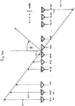
- the result for the first embodiment corresponds to a synthetic array as shown in FIG Fig. 3 is shown.
- the phases of the received signals of the synthetic array with only one active transmitter correspond to the phases of the real array with alternating transmitters.
- the beam swiveling is falsified by the Doppler effect. This is to be compensated by a Doppler filtering with a subsequent correction calculation.
- the superimposition of real and synthetic receiving antenna lines, the Doppler phase shift, and thus the correction calculation are measured as in the patent DE 102011113015.6 "Imaging radar sensor with synthetic enlargement of the antenna device and two-dimensional beam swiveling" carried out.
- the device comprises a frequency generator for generating signals that are emitted sequentially by the transmitting antennas, at least one processing unit for performing at least one linkage of the received signals emitted by the receiving antennas using the method of digital beam shaping to generate a bundled antenna beam, and a display device the position of the object.
- a device for beam swiveling to extreme swivel angles is provided with at least two switchable transmitting antennas.
- a plurality of receiving antennas arranged in a row are provided, the receiving antennas being arranged at a distance which corresponds to twice the distance necessary to swivel the beam in an unambiguous manner, the transmitting antennas in the first embodiment being arranged opposite one another at a distance, which corresponds to the distance that is required for a clear beam swivel.
- the device expediently has a number of 8, 16 or 32 receiving antennas.
- the position of the object can be displayed by means of the display device via an antenna diagram.
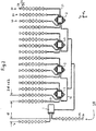
- the invention relates to a device according to claim 1, in particular a frequency-modulated continuous wave radar (FMCW radar) Fig. 1 , which monitors an area with the help of digital beamforming.
- the radar sensor consists of a transmitter with two outputs and several in this case sixteen recipients.
- Fig. 1 shows a transmitter with an integrated frequency modulator and 2 switchable outputs and 4 receiver blocks with four receiving channels each. The received signals are mixed down to a baseband in the receiver blocks.
- FIG 1 shows a radar sensor with a transmitter (1), two transmitting antennas (10), four receiver blocks (2) and sixteen receiving antennas (20).
- the transmitter (1) contains a modulator (16), a frequency generator (13), a frequency divider (14), an adjustable amplifier (12) and two switchable drivers (11).
- the frequency generator (13) generates an output signal with a continuously varying frequency between 76 and 77 GHz. The variation is brought about by the modulator (16).
- the output signal is sent to the amplifier (12), the amplitude of which is adjustable.
- the output signal of the amplifier (12) is output to the inputs of the two drivers (11), which can be switched on and off.
- the outputs of the drivers (11) each drive one of the transmitting antennas (10).
- the frequency generator (13) of the transmitter 2 also outputs a signal at its output to the frequency divider (14), which outputs an output signal which has half the frequency of the output signal of the frequency generator.
- the receiver blocks 2 each contain a frequency multiplier (22) and four mixers (21).
- the frequency multipliers (22) receive the output signal of the frequency divider (14) of the transmitter (1), each generate a signal with twice the frequency as their input signal, and each output their generated signals to the first inputs of the mixer (21).
- the mixers (21) are each connected to second inputs with a receiving antenna (20) each, so that the signal received by the receiving antenna is mixed down to a baseband in the mixer (21).
- the output signals of the mixer (21) are in a Figure 1 processing unit not shown evaluated.
- Fig. 2 Fig. 10 shows the physical arrangement of the antennas in a first embodiment. It shows the arrangement of the transmitting antennas (10) and the receiving antennas (20) in plan view.
- the transmitting antennas (10) and the receiving antennas (20) are designed as patch antennas which extend in an xy plane.
- the receiving antennas (20) each have so-called antenna rows (28), each of which consists of nine receiving beam elements (24) and connecting lines between them.
- the receiving beam elements (24) of an antenna line (28) are lined up one behind the other so that the antenna line (28) is elongated and extends in the y-direction.
- the antenna rows (28) from the receiving antenna (20) all run parallel to one another and are at the same height in relation to the y-direction.
- the antenna rows (28) are thus arranged next to one another in relation to the x-direction, the outer antenna rows being referred to as the right antenna row and the left antenna row.
- the z-direction points upwards from the drawing sheet.
- the z-direction is the direction in which objects are to be detected. For example, if the radar sensor is implemented in a land vehicle and is to detect objects in the direction of travel, the z-direction is the direction of travel.
- the antenna rows (28) each have a feed point with which they are connected to an input of the receiver block (2) via a stripline (23).
- the receiving antennas (20) each comprise only one antenna row (28), so that only one antenna row (28) is connected to an input of a receiver block (2) via its respective feed point.
- the two transmitting antennas (10) each contain a row of antennas (18).
- the antenna rows (18) each have transmitter beam elements (17) and connecting lines in between.
- the transmitter beam elements (17) of an antenna line (18) are lined up one behind the other so that the antenna line (18) is elongated and extends in the y-direction.
- the antenna rows (18) all run parallel to one another. However, the antenna rows (18) are related to each other the first direction (y) offset from one another. In relation to the second direction (x), the antenna rows are at a distance d from one another. The distance is always related to the phase centers of the respective antenna rows.
- the distance d2 between adjacent receiving antennas (20) is twice as large as the distance d between the transmitting antennas (10).
- a first of the transmission antennas (10) is fed in such a way that the feed takes place in the first direction y and a second of the transmission antennas (10) is fed in such a way that the feed takes place opposite to the first transmission antenna in direction (y).
- the transmitting antennas and the receiving antenna array typically have a vertical beam width of 10 degrees.
- the horizontal beam width of the transmitter is designed in such a way that the desired detection range of + -70 degrees is approximately illuminated. The same applies to the horizontal beam width of the individual lines of the receiving array.
- the receiver converts the received signals into the baseband and digitizes them in the correct phase.
- the signals emitted, reflected and received by the alternating transmitting antennas are now combined in the subsequent signal processor to form a synthetic array.
- the beam shaping and swiveling now takes place according to the "digital beamforming" method.
- Figure 3 shows the real aperture and the resulting synthetic arrangement according to a first embodiment.
- the signals of the individual lines are first weighted. This is typically done according to a so-called "Dolph-Chebychev" function.
- the signals of the individual lines are as shown in the Figures 4a and 4b outlined method by a multiple of the angle a in the phase.
- Figure 5 shows the antenna diagram without beam swiveling.
- the antenna diagram can be seen at an extreme swivel angle of 70 °. Because of the oblique viewing angle, the antenna beam is initially widened. Furthermore, the antenna gain is reduced, since the diagrams of the individual lines also have a reduced gain at this extreme angle. Likewise, the side lobes rise. However, the diagram is still good enough to recognize objects at the outer edge of the detection area. The angle measurement accuracy is reduced in accordance with the broadening of the main lobe of the array diagram.
Landscapes
- Engineering & Computer Science (AREA)
- Radar, Positioning & Navigation (AREA)
- Remote Sensing (AREA)
- Physics & Mathematics (AREA)
- Computer Networks & Wireless Communication (AREA)
- General Physics & Mathematics (AREA)
- Electromagnetism (AREA)
- Radar Systems Or Details Thereof (AREA)
- Variable-Direction Aerials And Aerial Arrays (AREA)
Claims (7)
- Dispositif de détermination de la position d'objets, en particulier d'objets en mouvement, comportant- au moins deux antennes d'émission commutables (10),- une multitude d'antennes de réception (20),- les antennes d'émission (10) et les antennes de réception (20) s'étendant respectivement longitudinalement, parallèlement les unes par rapport aux autres dans un premier sens (y), et les antennes de réception (10) étant disposées en une rangée et la rangée s'étendant dans un second sens (x), les antennes de réception voisines (20) ayant respectivement une distance d2 les unes par rapport aux autres,caractérisé en ce que
les antennes d'émission (10) sont décalées dans le premier sens (y) parallèlement à celui-ci, et ont, par rapport au deuxième sens (x), une distance d les unes par rapport aux autres, et que la distance d2 entre les antennes de réception voisines (20) est au moins le double de la distance d entre les antennes d'émission (10). - Dispositif selon la revendication 1,
dans lequel le nombre d'antennes d'émission utilisées dans la matrice d'antennes synthétique pour le formage de rayons est N, les antennes de réception (20) reçoivent des signaux d'une longueur d'onde λ et on a ce qui suit :
- Dispositif selon une des revendications 1 à 2,
dans lequel une première des antennes d'émission (10) est alimentée de manière à ce que l'alimentation ait lieu dans le premier sens (y) et une seconde des antennes d'émission (10) est alimentée de manière à ce que l'alimentation se fasse en sens inverse du premier sens (y). - Dispositif selon la revendication 1,
dans lequel le second sens (x) est perpendiculaire au premier sens (y). - Dispositif selon une des revendications précédentes, comportant un générateur de fréquence (13) pour la génération de signaux qui sont émis par une première des antennes d'émission (10) dans un premier cycle et par une seconde des antennes d'émission (10) dans un second cycle temporellement suivant.
- Dispositif selon une des revendications précédentes, caractérisé par un nombre de préférence de plus de 8, 16 ou 32, ou égal à 4 d'antennes de réception.
- Dispositif selon une des revendications précédentes, comportant un dispositif de restitution pour représenter ou pour émettre des données d'une position de l'objet.
Applications Claiming Priority (2)
| Application Number | Priority Date | Filing Date | Title |
|---|---|---|---|
| DE102011113018A DE102011113018A1 (de) | 2011-09-09 | 2011-09-09 | Abbildender Radarsensor mit schmaler Antennenkeule und weitem Winkel-Detektionsbereich |
| PCT/EP2012/003701 WO2013034281A1 (fr) | 2011-09-09 | 2012-09-04 | Capteur de radar imageur à lobe d'antenne étroit et zone de détection angulaire large |
Publications (2)
| Publication Number | Publication Date |
|---|---|
| EP2756329A1 EP2756329A1 (fr) | 2014-07-23 |
| EP2756329B1 true EP2756329B1 (fr) | 2021-07-07 |
Family
ID=47010472
Family Applications (1)
| Application Number | Title | Priority Date | Filing Date |
|---|---|---|---|
| EP12769898.3A Active EP2756329B1 (fr) | 2011-09-09 | 2012-09-04 | Capteur de radar imageur à lobe d'antenne étroit et zone de détection angulaire large |
Country Status (7)
| Country | Link |
|---|---|
| US (2) | US9817110B2 (fr) |
| EP (1) | EP2756329B1 (fr) |
| JP (2) | JP6259759B2 (fr) |
| KR (1) | KR101890974B1 (fr) |
| CN (1) | CN104067143B (fr) |
| DE (1) | DE102011113018A1 (fr) |
| WO (1) | WO2013034281A1 (fr) |
Families Citing this family (48)
| Publication number | Priority date | Publication date | Assignee | Title |
|---|---|---|---|---|
| DE102011113018A1 (de) | 2011-09-09 | 2013-03-14 | Astyx Gmbh | Abbildender Radarsensor mit schmaler Antennenkeule und weitem Winkel-Detektionsbereich |
| DE102014219113A1 (de) * | 2014-09-23 | 2016-03-24 | Robert Bosch Gmbh | MIMO-Radarvorrichtung zum entkoppelten Bestimmen eines Elevationswinkels und eines Azimutwinkels eines Objekts und Verfahren zum Betreiben einer MIMO-Radarvorrichtung |
| DE102014014864A1 (de) * | 2014-10-06 | 2016-04-07 | Astyx Gmbh | Abbildender Radarsensor mit horizontaler digitaler Strahlformung und vertikaler Objektvermessung durch Phasenvergleich bei zueinander versetzten Sendern |
| DE102014118031A1 (de) * | 2014-12-05 | 2016-06-09 | Astyx Gmbh | Radarsensor, Radarsensor-System sowie Verfahren zur Bestimmung der Position eines Objekts mit horizontaler und vertikaler digitaler Strahlformung zur Vermessung von punkt- und flächenförmig reflektierenden Objekten |
| KR101673200B1 (ko) * | 2015-01-06 | 2016-11-08 | 블루웨이브텔(주) | 중장비 차량용 근거리 패치배열 레이더 안테나 |
| KR102334415B1 (ko) * | 2015-09-24 | 2021-12-03 | 엘지이노텍 주식회사 | 안테나 장치 및 이를 포함하는 차량용 레이더 장치 |
| KR101709076B1 (ko) * | 2015-11-24 | 2017-02-22 | 현대자동차주식회사 | 안테나 장치 및 이를 포함하는 차량 |
| JP6469254B2 (ja) * | 2015-12-17 | 2019-02-13 | 三菱電機株式会社 | アンテナ装置 |
| JP6516160B2 (ja) * | 2016-02-15 | 2019-05-22 | マツダ株式会社 | レーダ装置を備えた車両 |
| DE102016203160A1 (de) * | 2016-02-29 | 2017-08-31 | Robert Bosch Gmbh | Radarsystem, umfassend eine Antennenanordnung zum Senden und Empfangen elektromagnetischer Strahlung |
| ES2968346T3 (es) * | 2016-04-20 | 2024-05-09 | Saab Ab | Procedimiento y sistema de operación de una antena IFF/SSR |
| CN106229687A (zh) * | 2016-07-12 | 2016-12-14 | 南开大学 | 基于网格形横向pin二极管的可编程控制的可重构天线 |
| TWI599787B (zh) * | 2016-08-01 | 2017-09-21 | 明泰科技股份有限公司 | 載具導航方法及系統 |
| KR102653129B1 (ko) | 2016-11-28 | 2024-04-02 | 주식회사 에이치엘클레무브 | 레이더 장치 및 그를 위한 안테나 장치 |
| KR102662232B1 (ko) | 2016-11-28 | 2024-05-02 | 주식회사 에이치엘클레무브 | 다중입력 다중출력 안테나부를 포함하는 레이더 장치 |
| DE102016224900A1 (de) * | 2016-12-14 | 2018-06-14 | Robert Bosch Gmbh | MIMO-Radarsensor für Kraftfahrzeuge |
| US10236966B2 (en) * | 2017-01-06 | 2019-03-19 | Skyworks Solutions, Inc. | Beamforming of harmonics |
| DE102017214575A1 (de) * | 2017-08-21 | 2019-02-21 | Astyx Gmbh | Abbildendes Radarsystem mit einem Empfangsarray zur Winkelbestimmung von Objekten in zwei Dimensionen durch eine gespreizte Anordnung der Empfangsantennen einer Dimension |
| KR102401176B1 (ko) * | 2017-09-14 | 2022-05-24 | 삼성전자주식회사 | 레이더 영상 처리 방법, 장치 및 시스템 |
| US11187795B2 (en) * | 2018-03-19 | 2021-11-30 | Panasonic Intellectual Property Management Co., Ltd. | Radar device |
| KR102157583B1 (ko) * | 2018-03-27 | 2020-09-18 | (주)스마트레이더시스템 | 레이더 장치 |
| KR102019171B1 (ko) * | 2018-03-27 | 2019-09-09 | (주)스마트레이더시스템 | 레이더 장치 |
| EP3572838B1 (fr) | 2018-03-27 | 2024-08-14 | Smart Radar System, Inc. | Dispositif radar |
| KR102167084B1 (ko) * | 2018-04-09 | 2020-10-16 | 주식회사 만도 | 레이더 장치 및 그를 위한 안테나 장치 |
| DE102018207686A1 (de) * | 2018-05-17 | 2019-11-21 | Robert Bosch Gmbh | MIMO-Radarsensor für Kraftfahrzeuge |
| CN110726969B (zh) * | 2018-07-16 | 2022-03-15 | 刘勉志 | 消防员定位系统 |
| TWI710227B (zh) * | 2018-08-17 | 2020-11-11 | 美商Idac控股公司 | 多trp之波束管理 |
| CN109799546A (zh) * | 2018-12-29 | 2019-05-24 | 清华大学 | 用于主动式毫米波安检成像的多发多收天线阵列布置、人体安检设备和人体安检方法 |
| CN109799545A (zh) * | 2018-12-29 | 2019-05-24 | 清华大学 | 用于主动式毫米波安检成像的多发多收天线阵列布置、人体安检设备和人体安检方法 |
| CN109782366A (zh) * | 2018-12-29 | 2019-05-21 | 清华大学 | 用于主动式毫米波安检成像的多发多收天线阵列布置、人体安检设备和方法 |
| CN109193179A (zh) * | 2018-09-20 | 2019-01-11 | 苏州大学 | 窄波束、宽测量范围的水平空域划分阵列天线 |
| KR102276975B1 (ko) * | 2018-10-25 | 2021-07-13 | 주식회사 비트센싱 | 레이더 장치 및 레이더 장치에 이용되는 안테나 장치 |
| JP2020085529A (ja) * | 2018-11-19 | 2020-06-04 | 株式会社デンソー | レーダ装置 |
| CN109444890B (zh) * | 2018-11-22 | 2020-06-05 | 成都汇蓉国科微系统技术有限公司 | 一种用于复杂条件下的雷达成像方法、系统及介质 |
| US11340329B2 (en) * | 2018-12-07 | 2022-05-24 | Apple Inc. | Electronic devices with broadband ranging capabilities |
| CN111427013A (zh) * | 2019-01-09 | 2020-07-17 | 华雷科技股份有限公司 | 具主波束波宽缩减与旁波束抑制功能的雷达装置 |
| US12140692B2 (en) | 2019-01-31 | 2024-11-12 | Mitsubishi Electric Corporation | Antenna device and radar apparatus |
| US11251523B2 (en) * | 2019-04-09 | 2022-02-15 | St Technologies Llc | Active array systems utilizing a thinned array |
| US12213421B2 (en) * | 2019-08-09 | 2025-02-04 | Beijing Dabeinong Biotechnology Co. Ltd. | Nucleic acid sequence for detecting soybean plant DBN8002 and detection method therefor |
| CN111180905B (zh) * | 2019-12-31 | 2021-07-20 | 福瑞泰克智能系统有限公司 | 阵列天线布阵和汽车 |
| CN111180866B (zh) * | 2019-12-31 | 2021-12-14 | 福瑞泰克智能系统有限公司 | 阵列天线布阵和汽车角雷达 |
| EP4016127A1 (fr) | 2020-12-16 | 2022-06-22 | Provizio Limited | Radar à entrées multiples à sortie dirigée (mimso) |
| KR102288673B1 (ko) * | 2020-12-28 | 2021-08-12 | 주식회사 비트센싱 | 수평 간격 및 수직 간격으로 배치되는 복수의 안테나를 포함하는 레이더 장치 |
| US20240219552A1 (en) * | 2021-04-30 | 2024-07-04 | Provizio Limited | Mimo radar using a frequency scanning antenna |
| CN113285211B (zh) * | 2021-06-30 | 2025-06-06 | 广州极飞科技股份有限公司 | 一种雷达天线、雷达装置及可移动平台 |
| CN114843795B (zh) * | 2022-05-31 | 2025-06-06 | 广州极飞科技股份有限公司 | 一种天线阵列以及雷达 |
| US12372641B2 (en) * | 2022-12-09 | 2025-07-29 | Nxp B.V. | Ego velocity estimator for radar systems |
| TWI903401B (zh) * | 2024-02-29 | 2025-11-01 | 和碩聯合科技股份有限公司 | 天線架構 |
Family Cites Families (32)
| Publication number | Priority date | Publication date | Assignee | Title |
|---|---|---|---|---|
| JP3511329B2 (ja) * | 1995-06-09 | 2004-03-29 | 本田技研工業株式会社 | 車載用レーダ装置 |
| JP3602258B2 (ja) * | 1996-05-02 | 2004-12-15 | 本田技研工業株式会社 | マルチビーム・レーダアンテナ |
| JPH11218574A (ja) | 1998-02-02 | 1999-08-10 | Mitsubishi Electric Corp | レーダ装置 |
| US6094172A (en) * | 1998-07-30 | 2000-07-25 | The United States Of America As Represented By The Secretary Of The Army | High performance traveling wave antenna for microwave and millimeter wave applications |
| JP2000230974A (ja) * | 1999-02-09 | 2000-08-22 | Toyota Motor Corp | レーダ装置 |
| JP2000235073A (ja) | 1999-02-15 | 2000-08-29 | Toyota Central Res & Dev Lab Inc | 多受信チャネルレーダ方式及び多受信チャネルレーダ装置 |
| JP2001183093A (ja) | 1999-12-28 | 2001-07-06 | Mitsubishi Electric Corp | 誘導装置 |
| US7183995B2 (en) * | 2001-08-16 | 2007-02-27 | Raytheon Company | Antenna configurations for reduced radar complexity |
| JP3575694B2 (ja) * | 2002-04-24 | 2004-10-13 | 株式会社ホンダエレシス | 走査型fmcwレーダ |
| US6970133B2 (en) * | 2003-06-04 | 2005-11-29 | Lockheed Martin Corporation | Antenna system and method of using same |
| JP4067456B2 (ja) * | 2003-06-09 | 2008-03-26 | 富士通テン株式会社 | レーダ装置及びその信号処理制御方法 |
| JP4545460B2 (ja) * | 2004-03-10 | 2010-09-15 | 三菱電機株式会社 | レーダ装置およびアンテナ装置 |
| JP2006003097A (ja) * | 2004-06-15 | 2006-01-05 | Fujitsu Ten Ltd | レーダ装置 |
| DE102004034429B4 (de) * | 2004-07-15 | 2009-12-24 | Augustin & Augustin GbR (vertretungsberechtigter Gesellschafter:Christian Augustin, 88709 Meersburg) | Radar Front-End |
| JP4833534B2 (ja) * | 2004-09-29 | 2011-12-07 | 富士通株式会社 | レーダ装置 |
| JP2006279525A (ja) | 2005-03-29 | 2006-10-12 | Honda Elesys Co Ltd | アンテナ |
| DE102005049772A1 (de) * | 2005-10-18 | 2007-04-19 | Robert Bosch Gmbh | Bewegungssensor sowie Verfahren zu seinem Betrieb |
| PL1989570T3 (pl) * | 2006-01-17 | 2017-02-28 | Teledyne Australia Pty Ltd. | Urządzenie i sposób do inwigilacji |
| JP2007333656A (ja) * | 2006-06-16 | 2007-12-27 | Murata Mfg Co Ltd | レーダ装置 |
| WO2008057286A2 (fr) * | 2006-10-27 | 2008-05-15 | Clariant Technologies Corp. | Procédé et appareil pour imagerie à micro-ondes et ondes millimétriques |
| US7609198B2 (en) * | 2007-05-21 | 2009-10-27 | Spatial Digital Systems, Inc. | Apparatus and method for radar imaging by measuring spatial frequency components |
| DE102007039897B3 (de) | 2007-08-23 | 2008-10-16 | Universität Karlsruhe (Th) | Verfahren zum Betrieb einer Antennengruppe mit mehreren Sendern und mehreren Empfängern sowie zugehörige Vorrichtung |
| JP5132338B2 (ja) | 2008-01-31 | 2013-01-30 | 三菱電機株式会社 | レーダ装置 |
| JP5378710B2 (ja) | 2008-06-11 | 2013-12-25 | 株式会社ダイヤコーポレーション | ゴルフ用アプローチ練習具 |
| DE102008038365A1 (de) * | 2008-07-02 | 2010-01-07 | Adc Automotive Distance Control Systems Gmbh | Fahrzeug-Radarsystem und Verfahren zur Bestimmung einer Position zumindest eines Objekts relativ zu einem Fahrzeug |
| DE102008061932A1 (de) * | 2008-12-12 | 2010-07-01 | Astyx Gmbh | Abbildender Radarsensor mit digitaler Strahlformung und synthetischer Vergrößerung der Antennenapertur |
| JP2010212895A (ja) * | 2009-03-09 | 2010-09-24 | Toshiba Corp | アンテナ装置、レーダ装置 |
| JP2010217035A (ja) * | 2009-03-17 | 2010-09-30 | Fujitsu Ten Ltd | レーダ装置 |
| JP2011033498A (ja) | 2009-08-03 | 2011-02-17 | Fujitsu Ten Ltd | レーダ装置 |
| DE102010002004A1 (de) * | 2010-02-16 | 2011-08-18 | Astyx GmbH, 85521 | Abstands- und Geschwindigkeitsmessvorrichtung und -verfahren |
| DE102011113018A1 (de) | 2011-09-09 | 2013-03-14 | Astyx Gmbh | Abbildender Radarsensor mit schmaler Antennenkeule und weitem Winkel-Detektionsbereich |
| EP2881752B1 (fr) | 2013-12-03 | 2017-05-10 | Nxp B.V. | Système radar automobile multipuces, puce de radar pour un tel système et procédé permettant de faire fonctionner un tel système |
-
2011
- 2011-09-09 DE DE102011113018A patent/DE102011113018A1/de not_active Withdrawn
-
2012
- 2012-09-04 EP EP12769898.3A patent/EP2756329B1/fr active Active
- 2012-09-04 CN CN201280055169.6A patent/CN104067143B/zh active Active
- 2012-09-04 JP JP2014528892A patent/JP6259759B2/ja active Active
- 2012-09-04 WO PCT/EP2012/003701 patent/WO2013034281A1/fr not_active Ceased
- 2012-09-04 US US14/343,848 patent/US9817110B2/en active Active
- 2012-09-04 KR KR1020147007428A patent/KR101890974B1/ko not_active Expired - Fee Related
-
2017
- 2017-07-06 JP JP2017132706A patent/JP6770489B2/ja active Active
- 2017-10-25 US US15/793,593 patent/US10852407B2/en active Active
Non-Patent Citations (1)
| Title |
|---|
| None * |
Also Published As
| Publication number | Publication date |
|---|---|
| CN104067143A (zh) | 2014-09-24 |
| US20180106895A1 (en) | 2018-04-19 |
| EP2756329A1 (fr) | 2014-07-23 |
| JP6770489B2 (ja) | 2020-10-14 |
| DE102011113018A1 (de) | 2013-03-14 |
| JP2017215328A (ja) | 2017-12-07 |
| US10852407B2 (en) | 2020-12-01 |
| KR20140063720A (ko) | 2014-05-27 |
| WO2013034281A1 (fr) | 2013-03-14 |
| WO2013034281A4 (fr) | 2013-05-30 |
| JP2014530343A (ja) | 2014-11-17 |
| JP6259759B2 (ja) | 2018-01-10 |
| CN104067143B (zh) | 2016-12-28 |
| US20140340253A1 (en) | 2014-11-20 |
| KR101890974B1 (ko) | 2018-08-22 |
| US9817110B2 (en) | 2017-11-14 |
Similar Documents
| Publication | Publication Date | Title |
|---|---|---|
| EP2756329B1 (fr) | Capteur de radar imageur à lobe d'antenne étroit et zone de détection angulaire large | |
| EP2753950B1 (fr) | Capteur de radar imageur à grossissement synthétique de l'ouverture d'antenne et à balayage bidimensionnel du faisceau | |
| DE112008000513B4 (de) | Elektronisch abtastendes Radarsystem | |
| EP2659285B1 (fr) | Capteur radar pour véhicules à moteur | |
| DE112007003175B4 (de) | Elektronisch abtastendes Radarsystem | |
| DE102004006519B4 (de) | Antennenanordnungsverfahren und Radarvorrichtung | |
| EP3673292B1 (fr) | Système radar d'imagerie avec un réseau de récepteurs pour la détermination de l'angle d'objets en deux dimensions par une disposition étalée des antennes de réception dans une dimension | |
| EP2534730B1 (fr) | Détecteur radar | |
| DE102004059915A1 (de) | Radarsystem | |
| DE112019006800T5 (de) | Antennenvorrichtung und Radarvorrichtung | |
| EP3227719A1 (fr) | Capteur radar, système de capteur radar, ainsi que procédé permettant de déterminer la position d'un objet par formation numérique horizontale et verticale de faisceaux pour mesurer des objets réfléchis sous forme de points ou de surfaces | |
| DE102006032539A1 (de) | FMCW-Radarsensor | |
| WO2012034736A1 (fr) | Capteur radar pour véhicules à moteur, notamment capteur lca | |
| WO2010066458A1 (fr) | Détecteur de radar imageur avec formation numérique du faisceau et agrandissement synthétique de l'ouverture d'antenne | |
| EP2193389B1 (fr) | Dispositif radar | |
| EP4073540B1 (fr) | Procédé de détermination d'au moins un élément d'informations d'objet concernant au moins un objet détecté au moyen d'un système radar et système radar | |
| EP2616839B1 (fr) | Capteur radar pour véhicules à moteur, notamment capteur rca | |
| DE102009047931B4 (de) | Verfahren und Vorrichtung zur Bestimmung von Abstand und Relativgeschwindigkeit wenigstens eines entfernten Objektes | |
| EP3811103B1 (fr) | Dispositif radar et procédé de fonctionnement d'un dispositif radar | |
| WO2004046752A1 (fr) | Procede et dispositif pour etablir une image radar au moyen d'un radar a ondes entretenues et modulation de frequence | |
| WO2000077544A1 (fr) | Dispositif et procede d'augmentation de la resolution angulaire d'un systeme d'antenne | |
| DE112019005668T5 (de) | Antennenvorrichtung und radarsystem | |
| DE102011051969B4 (de) | Radargerät und Verfahren zum Betreiben des Radargerätes | |
| EP1521098A1 (fr) | Procede et appareil sur le principe du radar FMCW | |
| DE102005062772A1 (de) | Radarvorrichtung |
Legal Events
| Date | Code | Title | Description |
|---|---|---|---|
| PUAI | Public reference made under article 153(3) epc to a published international application that has entered the european phase |
Free format text: ORIGINAL CODE: 0009012 |
|
| 17P | Request for examination filed |
Effective date: 20140409 |
|
| AK | Designated contracting states |
Kind code of ref document: A1 Designated state(s): AL AT BE BG CH CY CZ DE DK EE ES FI FR GB GR HR HU IE IS IT LI LT LU LV MC MK MT NL NO PL PT RO RS SE SI SK SM TR |
|
| DAX | Request for extension of the european patent (deleted) | ||
| STAA | Information on the status of an ep patent application or granted ep patent |
Free format text: STATUS: EXAMINATION IS IN PROGRESS |
|
| 17Q | First examination report despatched |
Effective date: 20181129 |
|
| GRAP | Despatch of communication of intention to grant a patent |
Free format text: ORIGINAL CODE: EPIDOSNIGR1 |
|
| STAA | Information on the status of an ep patent application or granted ep patent |
Free format text: STATUS: GRANT OF PATENT IS INTENDED |
|
| INTG | Intention to grant announced |
Effective date: 20210203 |
|
| GRAS | Grant fee paid |
Free format text: ORIGINAL CODE: EPIDOSNIGR3 |
|
| GRAA | (expected) grant |
Free format text: ORIGINAL CODE: 0009210 |
|
| STAA | Information on the status of an ep patent application or granted ep patent |
Free format text: STATUS: THE PATENT HAS BEEN GRANTED |
|
| AK | Designated contracting states |
Kind code of ref document: B1 Designated state(s): AL AT BE BG CH CY CZ DE DK EE ES FI FR GB GR HR HU IE IS IT LI LT LU LV MC MK MT NL NO PL PT RO RS SE SI SK SM TR |
|
| REG | Reference to a national code |
Ref country code: GB Ref legal event code: FG4D Free format text: NOT ENGLISH |
|
| REG | Reference to a national code |
Ref country code: AT Ref legal event code: REF Ref document number: 1409119 Country of ref document: AT Kind code of ref document: T Effective date: 20210715 |
|
| REG | Reference to a national code |
Ref country code: DE Ref legal event code: R096 Ref document number: 502012016832 Country of ref document: DE |
|
| REG | Reference to a national code |
Ref country code: IE Ref legal event code: FG4D Free format text: LANGUAGE OF EP DOCUMENT: GERMAN |
|
| REG | Reference to a national code |
Ref country code: LT Ref legal event code: MG9D |
|
| REG | Reference to a national code |
Ref country code: NL Ref legal event code: MP Effective date: 20210707 |
|
| PG25 | Lapsed in a contracting state [announced via postgrant information from national office to epo] |
Ref country code: HR Free format text: LAPSE BECAUSE OF FAILURE TO SUBMIT A TRANSLATION OF THE DESCRIPTION OR TO PAY THE FEE WITHIN THE PRESCRIBED TIME-LIMIT Effective date: 20210707 Ref country code: SE Free format text: LAPSE BECAUSE OF FAILURE TO SUBMIT A TRANSLATION OF THE DESCRIPTION OR TO PAY THE FEE WITHIN THE PRESCRIBED TIME-LIMIT Effective date: 20210707 Ref country code: BG Free format text: LAPSE BECAUSE OF FAILURE TO SUBMIT A TRANSLATION OF THE DESCRIPTION OR TO PAY THE FEE WITHIN THE PRESCRIBED TIME-LIMIT Effective date: 20211007 Ref country code: LT Free format text: LAPSE BECAUSE OF FAILURE TO SUBMIT A TRANSLATION OF THE DESCRIPTION OR TO PAY THE FEE WITHIN THE PRESCRIBED TIME-LIMIT Effective date: 20210707 Ref country code: RS Free format text: LAPSE BECAUSE OF FAILURE TO SUBMIT A TRANSLATION OF THE DESCRIPTION OR TO PAY THE FEE WITHIN THE PRESCRIBED TIME-LIMIT Effective date: 20210707 Ref country code: NO Free format text: LAPSE BECAUSE OF FAILURE TO SUBMIT A TRANSLATION OF THE DESCRIPTION OR TO PAY THE FEE WITHIN THE PRESCRIBED TIME-LIMIT Effective date: 20211007 Ref country code: NL Free format text: LAPSE BECAUSE OF FAILURE TO SUBMIT A TRANSLATION OF THE DESCRIPTION OR TO PAY THE FEE WITHIN THE PRESCRIBED TIME-LIMIT Effective date: 20210707 Ref country code: PT Free format text: LAPSE BECAUSE OF FAILURE TO SUBMIT A TRANSLATION OF THE DESCRIPTION OR TO PAY THE FEE WITHIN THE PRESCRIBED TIME-LIMIT Effective date: 20211108 Ref country code: FI Free format text: LAPSE BECAUSE OF FAILURE TO SUBMIT A TRANSLATION OF THE DESCRIPTION OR TO PAY THE FEE WITHIN THE PRESCRIBED TIME-LIMIT Effective date: 20210707 Ref country code: ES Free format text: LAPSE BECAUSE OF FAILURE TO SUBMIT A TRANSLATION OF THE DESCRIPTION OR TO PAY THE FEE WITHIN THE PRESCRIBED TIME-LIMIT Effective date: 20210707 |
|
| PG25 | Lapsed in a contracting state [announced via postgrant information from national office to epo] |
Ref country code: PL Free format text: LAPSE BECAUSE OF FAILURE TO SUBMIT A TRANSLATION OF THE DESCRIPTION OR TO PAY THE FEE WITHIN THE PRESCRIBED TIME-LIMIT Effective date: 20210707 Ref country code: LV Free format text: LAPSE BECAUSE OF FAILURE TO SUBMIT A TRANSLATION OF THE DESCRIPTION OR TO PAY THE FEE WITHIN THE PRESCRIBED TIME-LIMIT Effective date: 20210707 Ref country code: GR Free format text: LAPSE BECAUSE OF FAILURE TO SUBMIT A TRANSLATION OF THE DESCRIPTION OR TO PAY THE FEE WITHIN THE PRESCRIBED TIME-LIMIT Effective date: 20211008 |
|
| REG | Reference to a national code |
Ref country code: DE Ref legal event code: R097 Ref document number: 502012016832 Country of ref document: DE |
|
| PG25 | Lapsed in a contracting state [announced via postgrant information from national office to epo] |
Ref country code: DK Free format text: LAPSE BECAUSE OF FAILURE TO SUBMIT A TRANSLATION OF THE DESCRIPTION OR TO PAY THE FEE WITHIN THE PRESCRIBED TIME-LIMIT Effective date: 20210707 |
|
| REG | Reference to a national code |
Ref country code: CH Ref legal event code: PL |
|
| PLBE | No opposition filed within time limit |
Free format text: ORIGINAL CODE: 0009261 |
|
| STAA | Information on the status of an ep patent application or granted ep patent |
Free format text: STATUS: NO OPPOSITION FILED WITHIN TIME LIMIT |
|
| REG | Reference to a national code |
Ref country code: BE Ref legal event code: MM Effective date: 20210930 |
|
| PG25 | Lapsed in a contracting state [announced via postgrant information from national office to epo] |
Ref country code: SM Free format text: LAPSE BECAUSE OF FAILURE TO SUBMIT A TRANSLATION OF THE DESCRIPTION OR TO PAY THE FEE WITHIN THE PRESCRIBED TIME-LIMIT Effective date: 20210707 Ref country code: SK Free format text: LAPSE BECAUSE OF FAILURE TO SUBMIT A TRANSLATION OF THE DESCRIPTION OR TO PAY THE FEE WITHIN THE PRESCRIBED TIME-LIMIT Effective date: 20210707 Ref country code: RO Free format text: LAPSE BECAUSE OF FAILURE TO SUBMIT A TRANSLATION OF THE DESCRIPTION OR TO PAY THE FEE WITHIN THE PRESCRIBED TIME-LIMIT Effective date: 20210707 Ref country code: MC Free format text: LAPSE BECAUSE OF FAILURE TO SUBMIT A TRANSLATION OF THE DESCRIPTION OR TO PAY THE FEE WITHIN THE PRESCRIBED TIME-LIMIT Effective date: 20210707 Ref country code: EE Free format text: LAPSE BECAUSE OF FAILURE TO SUBMIT A TRANSLATION OF THE DESCRIPTION OR TO PAY THE FEE WITHIN THE PRESCRIBED TIME-LIMIT Effective date: 20210707 Ref country code: CZ Free format text: LAPSE BECAUSE OF FAILURE TO SUBMIT A TRANSLATION OF THE DESCRIPTION OR TO PAY THE FEE WITHIN THE PRESCRIBED TIME-LIMIT Effective date: 20210707 Ref country code: AL Free format text: LAPSE BECAUSE OF FAILURE TO SUBMIT A TRANSLATION OF THE DESCRIPTION OR TO PAY THE FEE WITHIN THE PRESCRIBED TIME-LIMIT Effective date: 20210707 |
|
| 26N | No opposition filed |
Effective date: 20220408 |
|
| PG25 | Lapsed in a contracting state [announced via postgrant information from national office to epo] |
Ref country code: LU Free format text: LAPSE BECAUSE OF NON-PAYMENT OF DUE FEES Effective date: 20210904 Ref country code: IT Free format text: LAPSE BECAUSE OF FAILURE TO SUBMIT A TRANSLATION OF THE DESCRIPTION OR TO PAY THE FEE WITHIN THE PRESCRIBED TIME-LIMIT Effective date: 20210707 Ref country code: IE Free format text: LAPSE BECAUSE OF NON-PAYMENT OF DUE FEES Effective date: 20210904 Ref country code: FR Free format text: LAPSE BECAUSE OF NON-PAYMENT OF DUE FEES Effective date: 20210907 Ref country code: BE Free format text: LAPSE BECAUSE OF NON-PAYMENT OF DUE FEES Effective date: 20210930 |
|
| PG25 | Lapsed in a contracting state [announced via postgrant information from national office to epo] |
Ref country code: LI Free format text: LAPSE BECAUSE OF NON-PAYMENT OF DUE FEES Effective date: 20210930 Ref country code: CH Free format text: LAPSE BECAUSE OF NON-PAYMENT OF DUE FEES Effective date: 20210930 |
|
| REG | Reference to a national code |
Ref country code: AT Ref legal event code: MM01 Ref document number: 1409119 Country of ref document: AT Kind code of ref document: T Effective date: 20210904 |
|
| PG25 | Lapsed in a contracting state [announced via postgrant information from national office to epo] |
Ref country code: AT Free format text: LAPSE BECAUSE OF NON-PAYMENT OF DUE FEES Effective date: 20210904 |
|
| PG25 | Lapsed in a contracting state [announced via postgrant information from national office to epo] |
Ref country code: HU Free format text: LAPSE BECAUSE OF FAILURE TO SUBMIT A TRANSLATION OF THE DESCRIPTION OR TO PAY THE FEE WITHIN THE PRESCRIBED TIME-LIMIT; INVALID AB INITIO Effective date: 20120904 Ref country code: CY Free format text: LAPSE BECAUSE OF FAILURE TO SUBMIT A TRANSLATION OF THE DESCRIPTION OR TO PAY THE FEE WITHIN THE PRESCRIBED TIME-LIMIT Effective date: 20210707 |
|
| P01 | Opt-out of the competence of the unified patent court (upc) registered |
Effective date: 20230526 |
|
| PG25 | Lapsed in a contracting state [announced via postgrant information from national office to epo] |
Ref country code: MK Free format text: LAPSE BECAUSE OF FAILURE TO SUBMIT A TRANSLATION OF THE DESCRIPTION OR TO PAY THE FEE WITHIN THE PRESCRIBED TIME-LIMIT Effective date: 20210707 |
|
| PG25 | Lapsed in a contracting state [announced via postgrant information from national office to epo] |
Ref country code: MT Free format text: LAPSE BECAUSE OF FAILURE TO SUBMIT A TRANSLATION OF THE DESCRIPTION OR TO PAY THE FEE WITHIN THE PRESCRIBED TIME-LIMIT Effective date: 20210707 |
|
| REG | Reference to a national code |
Ref country code: DE Ref legal event code: R081 Ref document number: 502012016832 Country of ref document: DE Owner name: CRUISE MUNICH GMBH, DE Free format text: FORMER OWNER: ASTYX GMBH, 85521 OTTOBRUNN, DE |
|
| REG | Reference to a national code |
Ref country code: DE Ref legal event code: R082 Ref document number: 502012016832 Country of ref document: DE Representative=s name: MANITZ FINSTERWALD PATENT- UND RECHTSANWALTSPA, DE |
|
| PGFP | Annual fee paid to national office [announced via postgrant information from national office to epo] |
Ref country code: DE Payment date: 20250926 Year of fee payment: 14 |
|
| PGFP | Annual fee paid to national office [announced via postgrant information from national office to epo] |
Ref country code: GB Payment date: 20250923 Year of fee payment: 14 |
|
| PG25 | Lapsed in a contracting state [announced via postgrant information from national office to epo] |
Ref country code: TR Free format text: LAPSE BECAUSE OF FAILURE TO SUBMIT A TRANSLATION OF THE DESCRIPTION OR TO PAY THE FEE WITHIN THE PRESCRIBED TIME-LIMIT Effective date: 20210707 |